1997 ACURA NSX display
[x] Cancel search: displayPage 152 of 1503
Kickback
1. The motor operates when the ABS is functioning, and the fluid in the reservoir is forced out to the master cylinder,
causing kickback at the brake pedal.
Pump Motor
1. The pump motor operates when the ABS is functioning.
2. The ABS control unit checks the pump motor operation during initial diagnosis when the vehicle is started. You may
hear the motor operate at this time, but it is normal.
Brake Fluid Replacement/Air Bleeding
1. Brake fluid replacement and air bleeding procedures are the same as vehicles without ABS. To ease bleeding, start
with the front wheels.
Troubleshooting
1. The troubleshooting flowcharts procedures assume that the cause of the problem is still present and the ABS indicator
is still on. Following the flowchart when the ABS indicator does not come on can result in incorrect diagnosis.
2. Question the customer about the conditions when the problem occurred, and try to reproduce the same conditions
for troubleshooting.
Find out when the ABS indicator came on, such as during initial diagnosis, during ABS control, after ABS control,
when vehicle speed was at a certain speed, etc.
3. When the ABS indicator does not come on during the test-drive, but troubleshooting is performed based on the DTC,
check for loose connectors, poor contact at the terminals, etc. before you start troubleshooting.
4. After troubleshooting, erase the DTC and test-drive the vehicle. Be sure the ABS indicator does not come on.
5. The connector illustrations show the female terminals with a single outline and the male terminals with a double outline.
ABS Function Test
To simulate ABS operation and activate the solenoid valves and pump, use the Honda PGM Tester.
Connect the PGM Tester to the 16P Data Link Connector (DLC). When the System Select menu is displayed, select the ABS
Test Mode menu and follow the tester's prompts.ProCarManuals.com
Page 714 of 1503
(cont'd)
Description
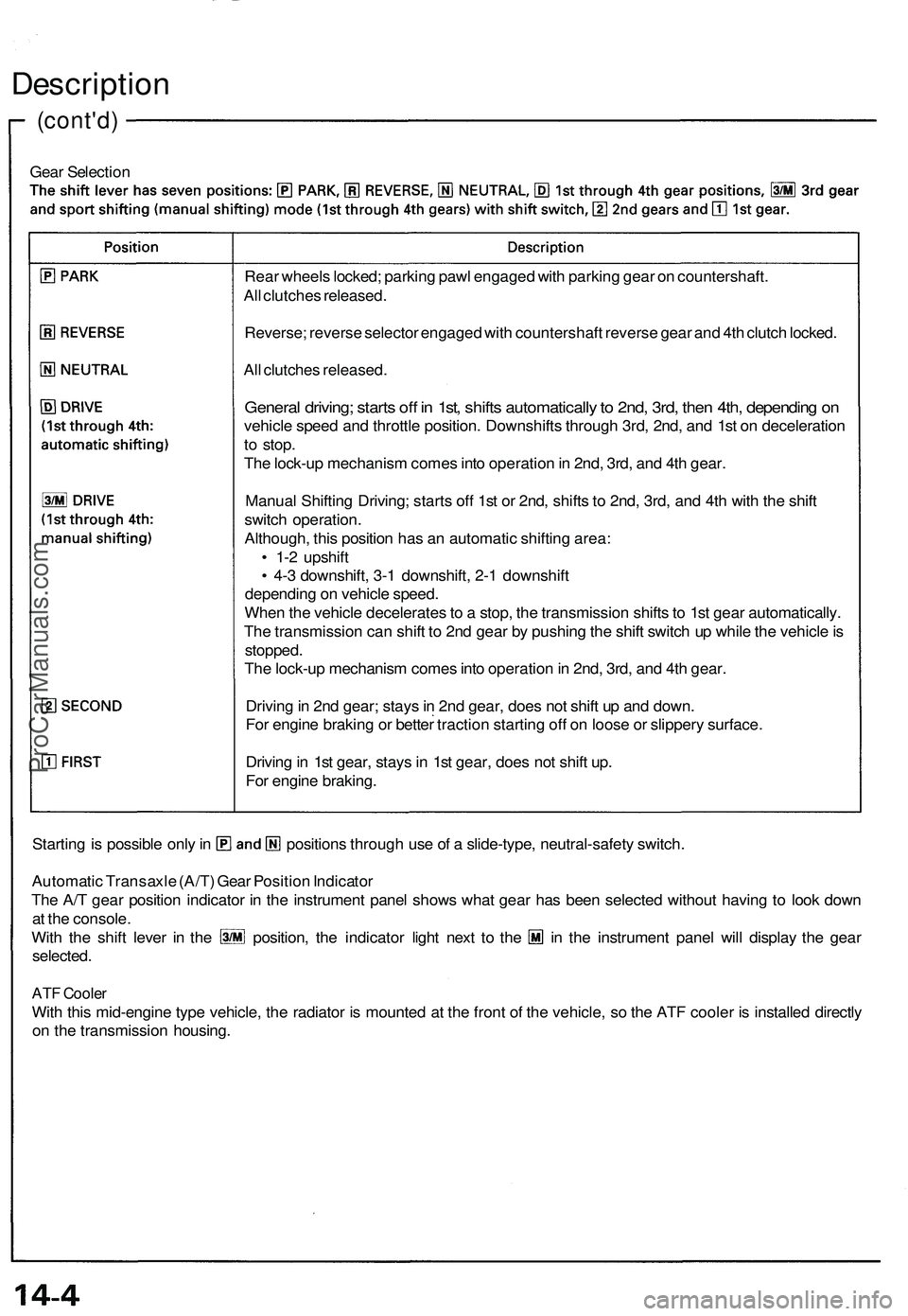
Gear Selection
Starting is possible only in positions through use of a slide-type, neutral-safety switch.
Automatic Transaxle (A/T) Gear Position Indicator
The A/T gear position indicator in the instrument panel shows what gear has been selected without having to look down
at the console.
With the shift lever in the position, the indicator light next to the in the instrument panel will display the gear
selected.
ATF Cooler
With this mid-engine type vehicle, the radiator is mounted at the front of the vehicle, so the ATF cooler is installed directly
on the transmission housing.
Rear wheels locked; parking pawl engaged with parking gear on countershaft.
All clutches released.
Reverse; reverse selector engaged with countershaft reverse gear and 4th clutch locked.
All clutches released.
General driving; starts off in 1st, shifts automatically to 2nd, 3rd, then 4th, depending on
vehicle speed and throttle position. Downshifts through 3rd, 2nd, and 1st on deceleration
to stop.
The lock-up mechanism comes into operation in 2nd, 3rd, and 4th gear.
Manual Shifting Driving; starts off 1st or 2nd, shifts to 2nd, 3rd, and 4th with the shift
switch operation.
Although, this position has an automatic shifting area:
• 1-2 upshift
• 4-3 downshift, 3-1 downshift, 2-1 downshift
depending on vehicle speed.
When the vehicle decelerates to a stop, the transmission shifts to 1st gear automatically.
The transmission can shift to 2nd gear by pushing the shift switch up while the vehicle is
stopped.
The lock-up mechanism comes into operation in 2nd, 3rd, and 4th gear.
Driving in 2nd gear; stays in 2nd gear, does not shift up and down.
For engine braking or better traction starting off on loose or slippery surface.
Driving in 1st gear, stays in 1st gear, does not shift up.
For engine braking.ProCarManuals.com
Page 725 of 1503
Shift Control
Engine torque controls shifting through the linear solenoid. The linear solenoid is controlled by the TCM, and it is used to
operate the throttle valve.
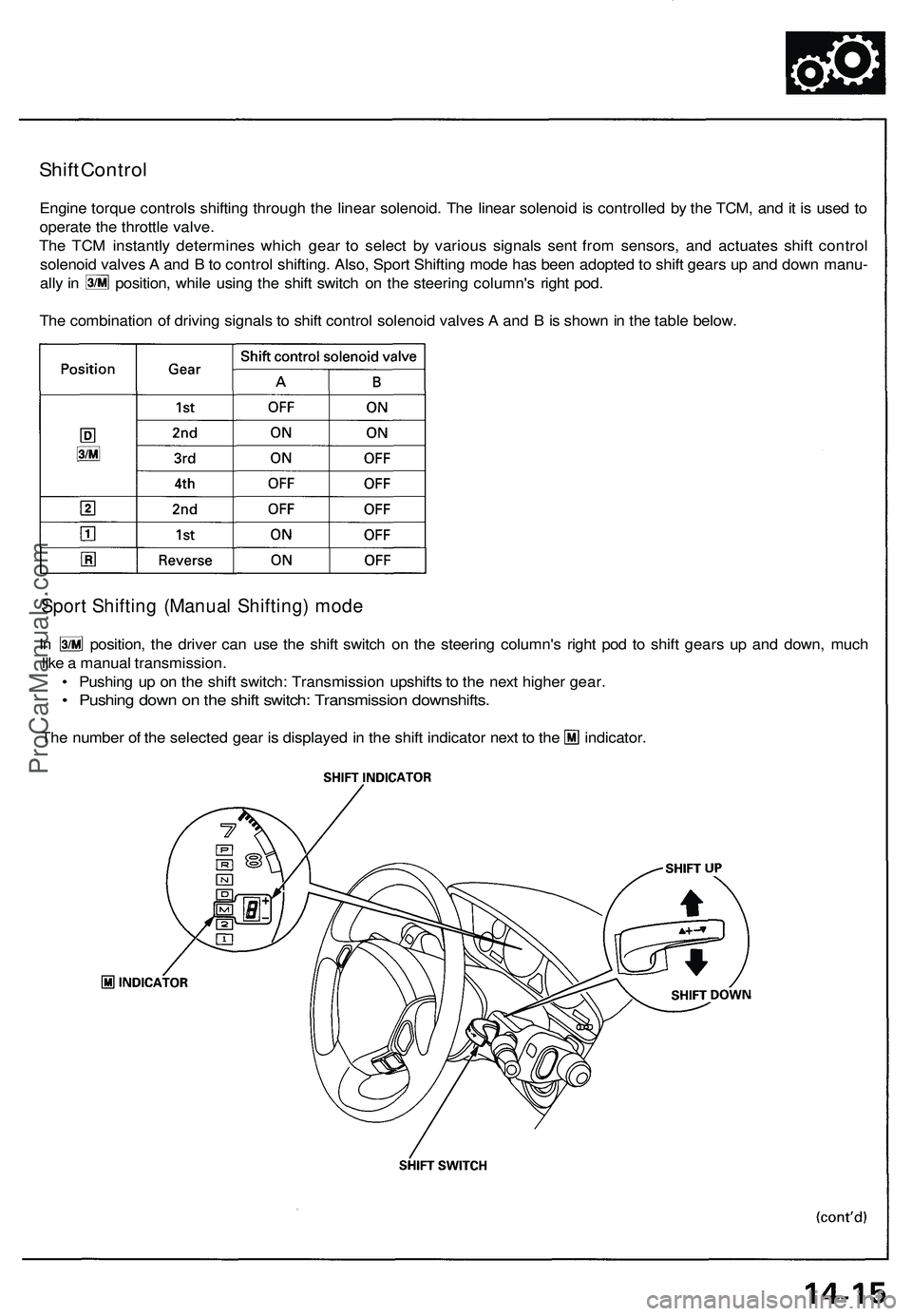
The TCM instantly determines which gear to select by various signals sent from sensors, and actuates shift control
solenoid valves A and B to control shifting. Also, Sport Shifting mode has been adopted to shift gears up and down manu-
ally in position, while using the shift switch on the steering column's right pod.
The combination of driving signals to shift control solenoid valves A and B is shown in the table below.
Sport Shifting (Manual Shifting) mode
In position, the driver can use the shift switch on the steering column's right pod to shift gears up and down, much
like a manual transmission.
• Pushing up on the shift switch: Transmission upshifts to the next higher gear.
• Pushing down on the shift switch: Transmission downshifts.
The number of the selected gear is displayed in the shift indicator next to the indicator.ProCarManuals.com
Page 1010 of 1503
Features/Construction/Operation
Anti-lock Brake System (ABS) Description
General
In a conventional brake system, if the brake pedal is depressed excessively, the wheels can lock before the vehicle comes
to a stop. In such a case, the stability of the vehicle is reduced if the rear wheels are locked, and maneuverability of the
vehicle is reduced if the front wheels are locked, creating an extremely unstable condition.
The Anti-lock Brake System (ABS) modulates the pressure of the brake fluid applied to each caliper, thereby preventing
the locking of the wheels, whenever the wheels are likely to locked due to be excessive braking. It then restores normal
hydraulic pressure when there is no longer any possibility of wheel locking.
4-Channel Anti-lock Brake System (ABS) Features
• Increased braking stability can be achieved regardless of changing driving conditions.
• The maneuverability of the vehicle is improved as the system prevents the front wheels from locking.
• When the anti-lock brake system goes into action, kickback is felt on the brake pedal.
• The anti-lock brake system is equipped with a self-diagnosis function. When an abnormality is detected, the ABS indi-
cator light comes on. The location of the abnormality can be diagnosed from the frequency of the system indicator
light display blinks.
• This system has individual control of the front and rear wheels. Braking force is controlled on each of the four wheels
independently, resulting in optimum braking efects on the four wheels.
The system has a fail-safe function that allows normal braking if there's a problem with the anti-lock brake system.
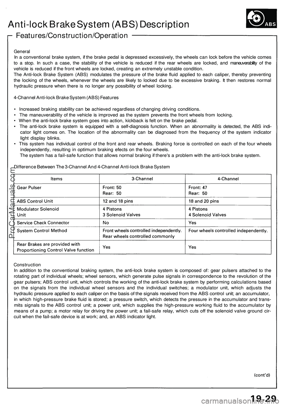
Difference Between The 3-Channel And 4-Channel Anti-lock Brake System
Construction
In addition to the conventional braking system, the anti-lock brake system is composed of: gear pulsers attached to the
rotating part of individual wheels; wheel sensors, which generate pulse signals in correspondence to the revolution of the
gear pulsers; ABS control unit, which controls the working of the anti-lock brake system by performing calculations based
on the signals from the individual wheel sensors and the individual switches; a modulator unit, which adjusts the
hydraulic pressure applied to each caliper on the basis of the signals received from the ABS control unit; an accumulator,
in which high-pressure brake fluid is stored; a pressure switch, which detects the pressure in the accumulator and trans-
mits signals to the ABS control unit; a power unit, which supplies the high-pressure working fluid to the accumulator by
means of a pump; a motor relay for driving the power unit; a fail-safe relay, which cuts off the solenoid valve ground cir-
cuit when the fail-safe device is at work; and, an ABS indicator light.ProCarManuals.com
Page 1192 of 1503
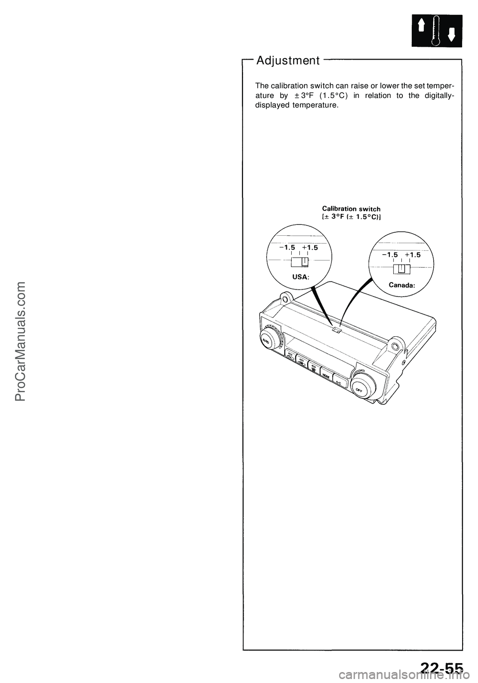
Adjustment
The calibration switch can raise or lower the set temper-
ature by ± 3°F (1.5°C) in relation to the digitally-
displayed temperature.ProCarManuals.com