1997 ACURA NSX tire pressure
[x] Cancel search: tire pressurePage 252 of 1503
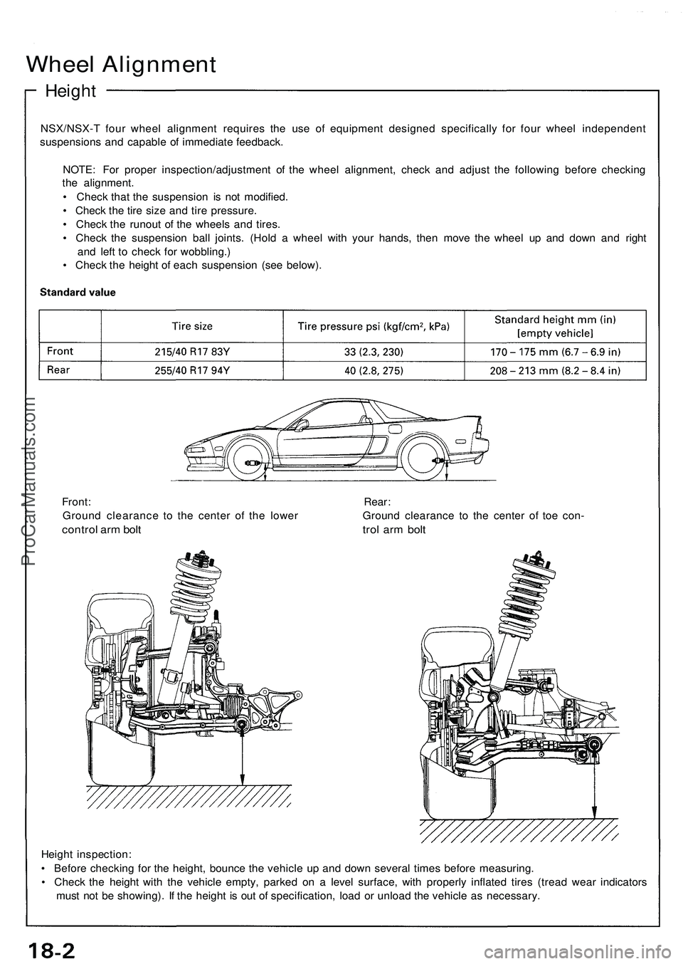
Wheel Alignment
Height
NSX/NSX- T fou r whee l alignmen t require s th e us e o f equipmen t designe d specificall y fo r fou r whee l independen t
suspension s an d capabl e o f immediat e feedback .
NOTE : Fo r prope r inspection/adjustmen t o f th e whee l alignment , chec k an d adjus t th e followin g befor e checkin g
th e alignment .
• Chec k tha t th e suspensio n i s no t modified .
• Chec k th e tir e siz e an d tir e pressure .
• Chec k th e runou t o f th e wheel s an d tires .
• Chec k th e suspensio n bal l joints . (Hol d a whee l wit h you r hands , the n mov e th e whee l u p an d dow n an d righ t
an d lef t t o chec k fo r wobbling. )
• Chec k th e heigh t o f eac h suspensio n (se e below) .
Heigh t inspection :
• Befor e checkin g fo r th e height , bounc e th e vehicl e u p an d dow n severa l time s befor e measuring .
• Chec k th e heigh t wit h th e vehicl e empty , parke d o n a leve l surface , wit h properl y inflate d tire s (trea d wea r indicator s
mus t no t b e showing) . I f th e heigh t i s ou t o f specification , loa d o r unloa d th e vehicl e a s necessary .
Front
: Rear :
Groun d clearanc e t o th e cente r o f th e lowe r Groun d clearanc e t o th e cente r o f toe con -
contro l ar m bol t tro l ar m bol t
ProCarManuals.com
Page 713 of 1503
Description
The automatic transmission is a combination of a 3-element torque converter and a triple-shaft electronically controlled
automatic transmission which provides 4 speeds forward and 1 speed reverse. The entire unit is positioned in line with the
engine.
Torque Converter, Gears, and Clutches
The torque converter consists of a pump, turbine, and stator, assembled in a single unit.
They are connected to the engine crankshaft so they turn together as a unit as the engine turns.
Around the outside of the torque converter is a ring gear which meshes with the starter pinion when the engine is being
started. The entire torque converter assembly serves as a flywheel while transmitting power to the transmission main-
shaft. The transmission has three parallel shafts: the mainshaft, the countershaft, and the secondary shaft. The mainshaft
is in line with the engine crankshaft.
The mainshaft includes the 1st and 4th clutches, and gears for 3rd, 4th, reverse, and 1st (3rd gear is integral with the main-
shaft, while reverse gear is integral with 4th gear).
The countershaft includes the 1st-hold and 3rd clutches, and gears for 2nd, 3rd, 4th, reverse, 1st, and parking.
The secondary shaft includes the 2nd clutch and gears for 2nd and 3rd.
The 4th and reverse gears can be locked to the countershaft at its center, providing 4th gear or reverse, depending on
which way the selector is moved.
The gears on the mainshaft and secondary shaft are in constant mesh with those on the countershaft.
When certain combinations of gears in the transmission are engaged by clutches, power is transmitted from the mainshaft
to the countershaft to provide positions.
Electronic Control
The electronic control system consists of the Transmission Control Module (TCM), sensors, a linear solenoid, a shift switch,
and 4 solenoid valves. Shifting and lock-up are electronically controlled for comfortable driving under all conditions.
The TCM is located on the insulator center bulkhead, behind the driver's seat.
Hydraulic Control
The valve bodies include the main valve body, secondary valve body, servo body, regulator valve body, throttle valve
body, lock-up valve body, and the 2nd accumulator body.
They are bolted to the torque converter housing as an assembly.
The main valve body contains the manual valve, 1-2 shift valve, 2-3 shift valve, 3-4 shift valve, relief valve, one-way relief
valve, and oil pump gears.
The secondary valve body contains the 3-2 kick-down valve, clutch pressure control (CPC) valve, 2nd orifice control valve, 3rd
orifice control valve, modulator valve, 4th exhaust valve, servo control valve, 2nd exhaust valve, and 4-3 kick-down valve.
The servo body contains the accumulator pistons and servo valve. The throttle valve body includes the throttle valve B
which is bolted to the servo body.
The regulator valve body contains the pressure regulator valve, lock-up control valve, and cooler relief valve. Fluid from
the regulator passes through the manual valve to the various control valves.
The lock-up valve body contains the lock-up timing B valve and lock-up shift valve. The 2nd accumulator body contains
the accumulator pistons and limited slip differential relief valve.
The torque converter check valve is located in the torque converter housing, under the main valve body.
The 1st, 1st-hold, 3rd, and 4th clutches receive fluid from their respective feed pipes and the 2nd clutch receives fluid from
the internal hydraulic circuit.
Shift Control Mechanism
Input from various sensors located throughout the vehicle determines which shift control solenoid valve the TCM will acti-
vate. Activating a shift control solenoid valve changes modulator pressure, causing a shift valve to move. This pressurizes
a line to one of the clutches, engaging that clutch and its corresponding gear.
Lock-up Mechanism
In position and position in 2nd, 3rd, and 4th, pressurized fluid is drained from the back of the torque converter
through a fluid passage, causing the lock-up piston to be held against the torque converter cover. As this takes place, the
mainshaft rotates at the same speed as the engine crankshaft. Together with hydraulic control, the TCM optimizes the tim-
ing of the lock-up mechanism.
The lock-up valves control the range of lock-up according to lock-up control solenoid valves A and B, and throttle valve B.
When lock-up control solenoid valves A and B activate, modulator pressure changes. The lock-up control solenoid valves
A and B are mounted on the torque converter housing, and are controlled by the TCM.
(cont'd)ProCarManuals.com
Page 939 of 1503
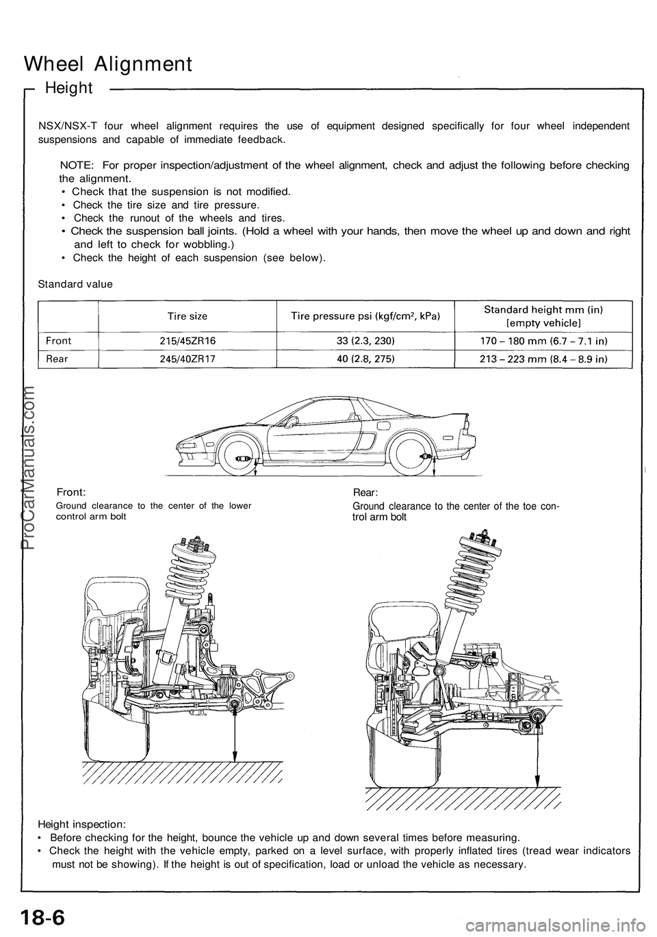
Wheel Alignment
Height
NSX/NSX-T four wheel alignment requires the use of equipment designed specifically for four wheel independent
suspensions and capable of immediate feedback.
NOTE: For proper inspection/adjustment of the wheel alignment, check and adjust the following before checking
the alignment.
• Check that the suspension is not modified.
• Check the tire size and tire pressure.
• Check the runout of the wheels and tires.
• Check the suspension ball joints. (Hold a wheel with your hands, then move the wheel up and down and right
and left to check for wobbling.)
• Check the height of each suspension (see below).
Standard value
Front:
Ground clearance to the center of the lower
control arm bolt
Rear:
Ground clearance to the center of the toe con-
trol arm bolt
Height inspection:
• Before checking for the height, bounce the vehicle up and down several times before measuring.
• Check the height with the vehicle empty, parked on a level surface, with properly inflated tires (tread wear indicators
must not be showing). If the height is out of specification, load or unload the vehicle as necessary.ProCarManuals.com
Page 940 of 1503
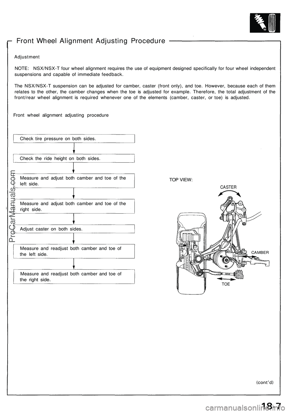
Front Wheel Alignment Adjusting Procedure
Adjustment
NOTE: NSX/NSX-T four wheel alignment requires the use of equipment designed specifically for four wheel independent
suspensions and capable of immediate feedback.
The NSX/NSX-T suspension can be adjusted for camber, caster (front only), and toe. However, because each of them
relates to the other, the camber changes when the toe is adjusted for example. Therefore, the total adjustment of the
front/rear wheel alignment is required whenever one of the elements (camber, caster, or toe) is adjusted.
Front wheel alignment adjusting procedure
Measure and adjust both camber and toe of the
left side.
Measure and adjust both camber and toe of the
right side.
Adjust caster on both sides.
Measure and readjust both camber and toe of
the left side.
Measure and readjust both camber and toe of
the right side.
TOP VIEW:
CASTER
TOE
CAMBER
Check tire pressure on both sides.
Check the ride height on both sides.ProCarManuals.com
Page 944 of 1503
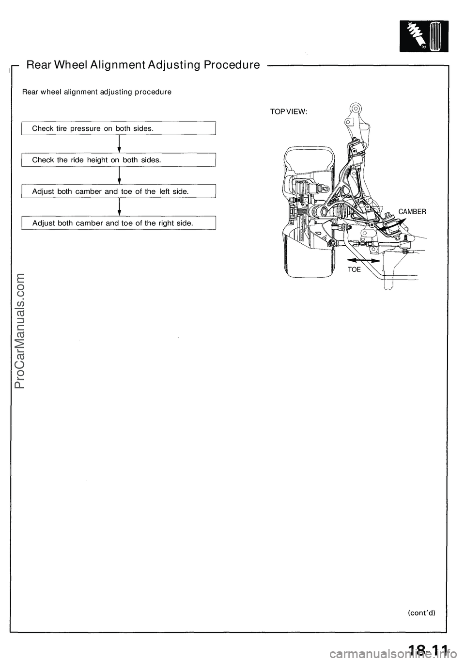
Rear Wheel Alignment Adjusting Procedure
Rear wheel alignment adjusting procedure
Check tire pressure on both sides.
Check the ride height on both sides.
Adjust both camber and toe of the left side.
Adjust both camber and toe of the right side.
TOP VIEW:
CAMBER
TOEProCarManuals.com
Page 1018 of 1503
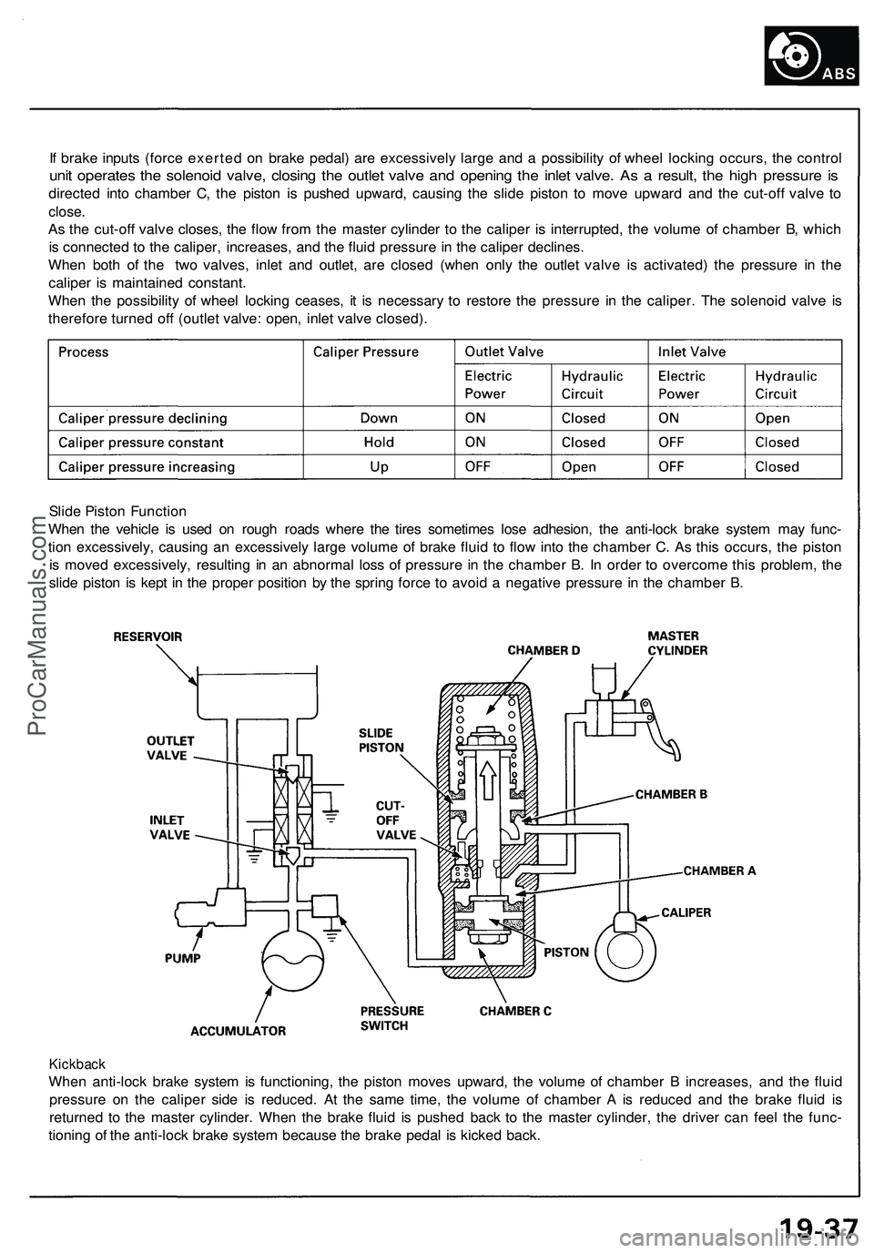
If brake inputs (force exerted on brake pedal) are excessively large and a possibility of wheel locking occurs, the control
unit operates the solenoid valve, closing the outlet valve and opening the inlet valve. As a result, the high pressure is
directed into chamber C, the piston is pushed upward, causing the slide piston to move upward and the cut-off valve to
close.
As the cut-off valve closes, the flow from the master cylinder to the caliper is interrupted, the volume of chamber B, which
is connected to the caliper, increases, and the fluid pressure in the caliper declines.
When both of the two valves, inlet and outlet, are closed (when only the outlet valve is activated) the pressure in the
caliper is maintained constant.
When the possibility of wheel locking ceases, it is necessary to restore the pressure in the caliper. The solenoid valve is
therefore turned off (outlet valve: open, inlet valve closed).
Slide Piston Function
When the vehicle is used on rough roads where the tires sometimes lose adhesion, the anti-lock brake system may func-
tion excessively, causing an excessively large volume of brake fluid to flow into the chamber C. As this occurs, the piston
is moved excessively, resulting in an abnormal loss of pressure in the chamber B. In order to overcome this problem, the
slide piston is kept in the proper position by the spring force to avoid a negative pressure in the chamber B.
Kickback
When anti-lock brake system is functioning, the piston moves upward, the volume of chamber B increases, and the fluid
pressure on the caliper side is reduced. At the same time, the volume of chamber A is reduced and the brake fluid is
returned to the master cylinder. When the brake fluid is pushed back to the master cylinder, the driver can feel the func-
tioning of the anti-lock brake system because the brake pedal is kicked back.ProCarManuals.com