1997 ACURA NSX alternator
[x] Cancel search: alternatorPage 141 of 1503

Pulsed Secondary Air Injection System Description
The air pump system is designed to advance the activation of the catalyst and to reduce the hydrocarbons (HC), carbon
monoxide (CO), and oxides of nitrogen (NOx) in the exhaust gas.
The system operates after the engine starts under the following conditions:
• The engine coolant temperature is between 0°C and 70°C (32°F and 158°F).
• The difference in engine coolant temperature is more than 20°C (36°F) between the time when the engine is started and
when the engine is stopped in the previous driving cycle.
AIR CONTROL
SOLENOID VALVE
AIR CONTROL
VALVE
WHT
AIR PUMP
RELAY
From
No. 5 BACK-UP LIGHTS
ALTERNATOR
TURN SIGNALS
(15 A) FUSE
From
AIR PUMP
(60 A) FUSE
AIR CONTROL VALVE
VACUUM TANK
AIR CONTROL VALVE
CHECK VALVE
When the engine is started, the air pump runs and sends fresh air to the air control valve. The air control valve allows the
fresh air to flow to the exhaust ports when its diaphragm is pulled by engine vacuum. It gets engine vacuum from the air
control solenoid, which is activated by the ECM. Once the fresh air flows into the exhaust ports near the exhaust valves, it
reacts with the exhaust gases, raising exhaust gas temperatures. This promotes faster warm-up of the catalytic converter.
The system operates for a maximum of 60 seconds, but the running time shortens in relation to the engine coolant tem-
perature and the intake air temperature. When the system is not operating, the air control solenoid and the air control
valve are closed to prevent exhaust gases from entering the system.
AIR PUMP
ELECTRICAL
CURRENT
SENSORProCarManuals.com
Page 370 of 1503
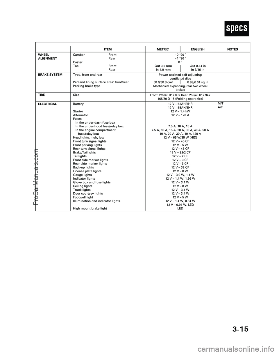
3-15
T
ITEMMETRICENGLISH
ELECTRICALBattery
Starter
Alternator
Fuses
In the under-dash fuse box
In the under-hood fuse/relay box
In the engine compartment
fuse/relay box
Headlights, high, low
Front turn signal lights
Front parking lights
Rear turn signal lights
Brake/Taillights
Taillights
Front side marker lights
Rear side marker lights
Back-up lights
License plate lights
Gauge lights
Indicator lights
Glove box and fuse lights
Ceiling lights
Trunk lights
Door courtesy lights
Footwell light
Illumination and indicator lights
High mount brake light12 V – 52AH/5HR
12 V – 55AH/5HR
12 V – 1.4 kW
12 V – 120 A
7.5 A, 10 A, 15 A
7.5 A, 10 A, 15 A, 20 A, 30 A, 40 A, 50 A
10 A, 20 A, 30 A, 40 A, 120 A
12 V – 65 W/35 W (HID)
12 V – 45 CP
12 V – 5 W
12 V – 45 CP
12 V – 32/2 CP
12 V – 2 CP
12 V – 3 CP
12 V – 3 CP
12 V – 32 CP
12 V – 8 W
12 V – 3.0 W, 1.4 W
12 V – 1.4 W, 1.96 W
12 V – 3.4 W
12 V – 8 W
12 V – 3.4 W
12 V – 3.4 W
12 V – 5 W
12 V – 1.4 W, 0.84 W
12 V – 0.91 W, LED
LED
TIRE
M/T
A/T
BRAKE SYSTEM
Front: 215/40 R17 83Y Rear: 255/40 R17 94Y165/80 D 16 (Folding spare tire)
Power assisted self-adjusting
ventilated disc
58.0/38.8 cm
28.99/6.01 sq in
Mechanical expanding, rear two wheel
brakes
WHEEL
ALIGNMENTCamber Front
Rear
Caster
Toe Front
Rear–0 °20 ’
–1 °30 ’
8 °
Out 3.5 mm Out 0.14 in
In 4.0 mm In 3/16 in
NOTES
Size
Type, front and rear
Pad and lining surface area: front/rear
Parking brake type
*04-NSX (61SW004)SEC03(01-16) 9/22/04 1:49 PM Page 3-15
ProCarManuals.com
Page 375 of 1503
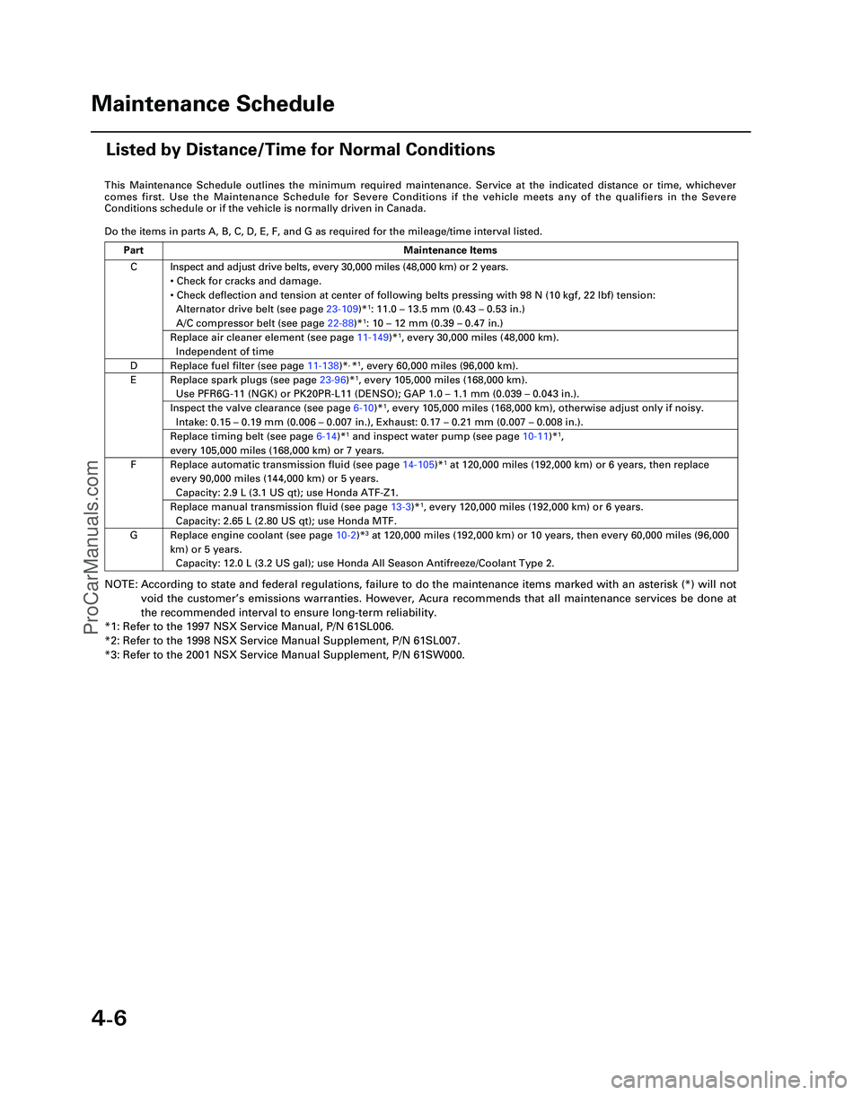
4-6
This Maintenance Schedule outlines the minimum required maintenance. Ser\
vice at the indicated distance or time, whichever
comes first. Use the Maintenance Schedule for Severe Conditions if the v\
ehicle meets any of the qualifiers in the Severe
Conditions schedule or if the vehicle is normally driven in Canada.
Do the items in parts A, B, C, D, E, F, and G as required for the mileag\
e/time interval listed.
NOTE: According to state and federal regulations, failure to do the maintenanc\
e items marked with an asterisk (*) will not
void the customer ’s emissions warranties. However, Acura recommends that all maintenance s\
ervices be done at
the recommended interval to ensure long-term reliability.
*1: Refer to the 1997 NSX Service Manual, P/N 61SL006.
*2: Refer to the 1998 NSX Service Manual Supplement, P/N 61SL007.
*3: Refer to the 2001 NSX Service Manual Supplement, P/N 61SW000.
C
D
E
F
G Inspect and adjust drive belts, every 30,000 miles (48,000 km) or 2 ye\
ars.
•
Check for cracks and damage.
• Check deflection and tension at center of following belts pressing with\
98 N (10 kgf, 22 lbf) tension:
Alternator drive belt (see page 23-109)*
1: 11.0 – 13.5 mm (0.43 – 0.53 in.)
A/C compressor belt (see page 22-88)*1: 10 – 12 mm (0.39 – 0.47 in.)
Replace air cleaner element (see page 11-149)*1, every 30,000 miles (48,000 km).
Independent of time
Replace fuel filter (see page 11-138)*, *1, every 60,000 miles (96,000 km).
Replace spark plugs (see page 23-96)*1, every 105,000 miles (168,000 km).
Use PFR6G-11 (NGK) or PK20PR-L11 (DENSO); GAP 1.0 – 1.1 mm (0.039 – 0.043 in.).
Inspect the valve clearance (see page 6-10)*1, every 105,000 miles (168,000 km), otherwise adjust only if noisy.
Intake: 0.15 – 0.19 mm (0.006 – 0.007 in.), Exhaust: 0.17 – 0.21 mm (0.007 – 0.008 in.).
Replace timing belt (see page 6-14)*1 and inspect water pump (see page 10-11)*1,
every 105,000 miles (168,000 km) or 7 years.
Replace automatic transmission fluid (see page 14-105)*1 at 120,000 miles (192,000 km) or 6 years, then replace
every 90,000 miles (144,000 km) or 5 years.
Capacity: 2.9 L (3.1 US qt); use Honda ATF-Z1.
Replace manual transmission fluid (see page 13-3)*1, every 120,000 miles (192,000 km) or 6 years.
Capacity: 2.65 L (2.80 US qt); use Honda MTF.
Replace engine coolant (see page 10-2 )*3 at 120,000 miles (192,000 km) or 10 years, then every 60,000 miles (9\
6,000
km) or 5 years. Capacity: 12.0 L (3.2 US gal); use Honda All Season Antifreeze/Coolant\
Type 2.
Part Maintenance Items
Maintenance Schedule
Listed by Distance/Time for Normal Conditions
*05-NSX (61SW004)SEC04(01-10) 9/22/04 1:49 PM Page 4-6
ProCarManuals.com
Page 416 of 1503
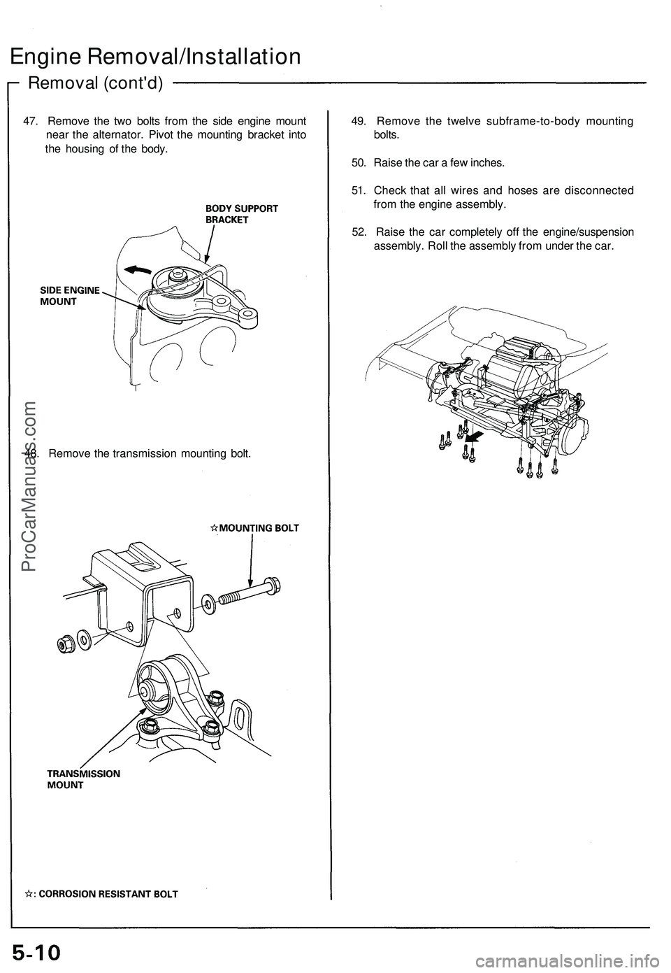
Removal (cont'd)
Engine Removal/Installation
47. Remove the two bolts from the side engine mount
near the alternator. Pivot the mounting bracket into
the housing of the body.
49. Remove the twelve subframe-to-body mounting
bolts.
50. Raise the car a few inches.
51. Check that all wires and hoses are disconnected
from the engine assembly.
52. Raise the car completely off the engine/suspension
assembly. Roll the assembly from under the car.
48. Remove the transmission mounting bolt.ProCarManuals.com
Page 433 of 1503
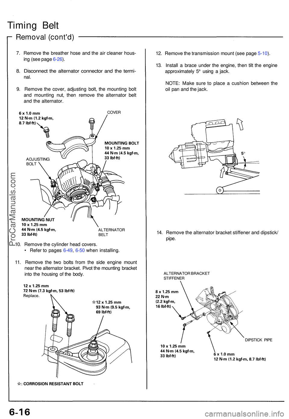
Timing Bel t
Remova l (cont'd )
7. Remov e th e breathe r hos e an d th e ai r cleaner hous-
in g (se e pag e 6-26 ).
8 . Disconnec t th e alternato r connecto r an d th e termi -
nal.
9. Remov e th e cover , adjustin g bolt , th e mountin g bol t
an d mountin g nut , the n remov e th e alternato r bel t
an d th e alternator .
COVER
ADJUSTIN GBOLT
ALTERNATO RBELT
12. Remov e th e transmissio n moun t (se e pag e 5-10 ).
13 . Instal l a brac e unde r th e engine , the n til t th e engin e
approximatel y 5 ° usin g a jack .
NOTE : Mak e sur e t o plac e a cushio n betwee n th e
oi l pa n an d th e jack .
14 . Remov e th e alternato r bracke t stiffene r an d dipstick /
pipe .
ALTERNATO R BRACKE TSTIFFENE R
DIPSTICK PIP E
10. Remov e th e cylinde r hea d covers .
• Refe r t o page s 6-49 , 6-5 0 whe n installing .
11 . Remov e th e tw o bolt s fro m th e sid e engin e moun t
nea r th e alternato r bracket . Pivo t th e mountin g bracke t
int o th e housin g o f th e body .
ProCarManuals.com
Page 445 of 1503
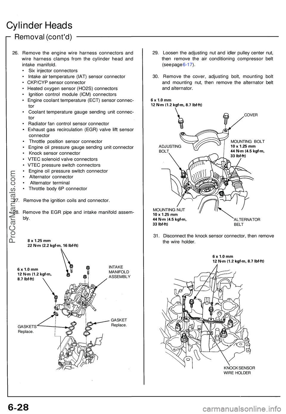
Cylinder Head s
Remova l (cont'd )
26. Remov e th e engin e wir e harnes s connector s an d
wir e harnes s clamp s fro m th e cylinde r hea d an d
intak e manifold .
• Si x injecto r connector s
• Intak e ai r temperatur e (IAT ) senso r connecto r
• CKP/CY P senso r connecto r
• Heate d oxyge n senso r (HO2S ) connector s
• Ignitio n contro l modul e (ICM ) connector s
• Engin e coolan t temperatur e (ECT ) senso r connec -
tor
• Coolan t temperatur e gaug e sendin g uni t connec -
tor
• Radiato r fa n contro l senso r connecto r
• Exhaust gas recirculatio n (EGR ) valv e lift senso r
connecto r
• Throttl e positio n senso r connecto r
• Engin e oi l pressur e gaug e sendin g uni t connecto r
• Knoc k senso r connecto r
• VTE C solenoi d valv e connector s
• VTE C pressur e switc h connector s
• Engin e oi l pressur e switc h connecto r
• Alternato r connecto r
• Alternato r termina l
• Throttl e bod y 6 P connecto r
27 . Remov e th e ignitio n coil s an d connector .
28 . Remov e th e EG R pip e an d intak e manifol d assem -
bly.
GASKET SReplace.
INTAKEMANIFOL DASSEMBL Y
GASKETReplace .
29. Loose n th e adjustin g nu t an d idle r pulle y cente r nut ,
the n remov e th e ai r conditionin g compresso r bel t
(se e pag e 6-17 ).
30 . Remov e th e cover , adjustin g bolt , mountin g bol t
an d mountin g nut , the n remov e th e alternato r bel t
an d alternator .
COVER
ADJUSTIN GBOLT
MOUNTIN G BOL T
MOUNTIN G NU T
ALTERNATO RBELT
31. Disconnec t th e knoc k senso r connector , the n remov e
th e wir e holder .
KNOCK SENSO RWIRE HOLDE R
ProCarManuals.com
Page 587 of 1503
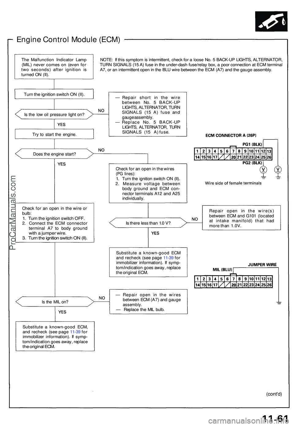
Engine Contro l Modul e (ECM )
NOTE: I f thi s sympto m is intermittent , chec k fo r a loos e No . 5 BACK-U P LIGHTS , ALTERNATOR ,
TUR N SIGNAL S (1 5 A ) fus e in th e under-das h fuse/rela y box , a poo r connectio n a t EC M termina l
A7 , o r a n intermitten t ope n in th e BL U wir e betwee n th e EC M (A7 ) an d th e gaug e assembly .
I s th e lo w oi l pressur e ligh t on ?
Tr y t o star t th e engine .
Doe s th e engin e start ?
Chec k fo r a n ope n in th e wir e o r
bulb :
1. Tur n th e ignitio n switc h OFF .2. Connec t th e EC M connecto r
termina l A 7 t o bod y groun d
with a jumpe r wire .3. Tur n th e ignitio n switc h O N (II) .
Is th e MI L on ?
Substitut e a known-goo d ECM ,
an d rechec k (se e pag e 11-3 9 fo r
immobilize r information) . I f symp -
tom/indicatio n goe s away , replac e
the origina l ECM .
— Repai r shor t i n the wir e
betwee n No . 5 BACK-U P
LIGHTS , ALTERNATOR , TUR N
SIGNAL S (1 5 A ) fus e an d
gaug e assembly .
— Replac e No . 5 BACK-U P
LIGHTS , ALTERNATOR , TUR N
SIGNALS (15 A) fuse.
Chec k fo r a n ope n in th e wire s
(PG lines) :1. Tur n th e ignitio n switc h O N (II) .
2 . Measur e voltag e betwee n
bod y groun d an d EC M con -
necto r terminal s A1 2 an d A2 5
individually .
I s ther e les s tha n 1. 0 V ?
Substitut e a known-goo d EC M
an d rechec k (se e pag e 11-3 9 fo r
immobilize r information) . I f symp -
tom/indicatio n goe s away , replac e
th e origina l ECM . Repai
r ope n i n th e wire(s )
betwee n EC M an d G10 1 (locate d
a t intak e manifold ) tha t ha d
mor e tha n 1.0V .
— Repai r ope n i n th e wire s
betwee n EC M (A7 ) an d gaug e
assembly .— Replac e th e MI L bulb .
(cont'd )
Turn th e ignitio n switc h O N (II) .
The Malfunctio n Indicato r Lam p
(MIL ) neve r come s o n (eve n fo r
tw o seconds ) afte r ignitio n i s
turne d O N (II) .
ProCarManuals.com
Page 628 of 1503
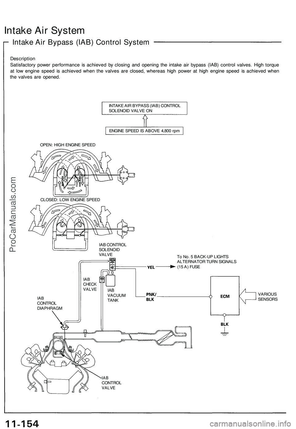
Intake Air System
Intake Air Bypass (IAB) Control System
Description
Satisfactory power performance is achieved by closing and opening the intake air bypass (IAB) control valves. High torque
at low engine speed is achieved when the valves are closed, whereas high power at high engine speed is achieved when
the valves are opened.
INTAKE AIR BYPASS (IAB) CONTROL
SOLENOID VALVE ON
ENGINE SPEED IS ABOVE 4,800 rpm
OPEN: HIGH ENGINE SPEED
CLOSED: LOW ENGINE SPEED
IAB CONTROL
SOLENOID
VALVE
To No. 5 BACK-UP LIGHTS
ALTERNATOR TURN SIGNALS
(15 A) FUSE
IAB
CONTROL
DIAPHRAGM
•IAB
CONTROL
VALVE
IAB
CHECK
VALVE
IAB
VACUUM
TANK
VARIOUS
SENSORSProCarManuals.com