Page 634 of 1503
Exhaust Gas Recirculation (EGR) System
The EGR system is designed to reduce oxides of nitrogen emissions (NOx) by recirculating exhaust gas through the EGR
valve and the intake manifold into the combustion chambers. It is composed of the EGR valve, EGR vacuum control valve,
EGR control solenoid valve, ECM and various sensors.
The ECM contains memories for ideal EGR valve lifts for varying operating conditions. The EGR valve lift sensor detects
the amount of EGR valve lift and sends the information to the ECM. The ECM then compares it with the ideal EGR valve lift
which is determined by signals sent from the other sensors. If there is any difference between the two, the ECM varies cur-
rent to the EGR control solenoid valve to regulate vacuum applied to the EGR valve.
EGR
VALVE
LIFT
SENSOR
INTAKE
MANIFOLD
EGR
CONTROL
SOLENOID
VALVE
To No. 5 BACK-UP
LIGHTS ALTERNATOR
TURN SIGNALS
(15 A) FUSE
-EGR
VACUUM
CONTROL
VALVE
(cont'd)
EGR
VALVE
VARIOUS
SENSORSProCarManuals.com
Page 636 of 1503
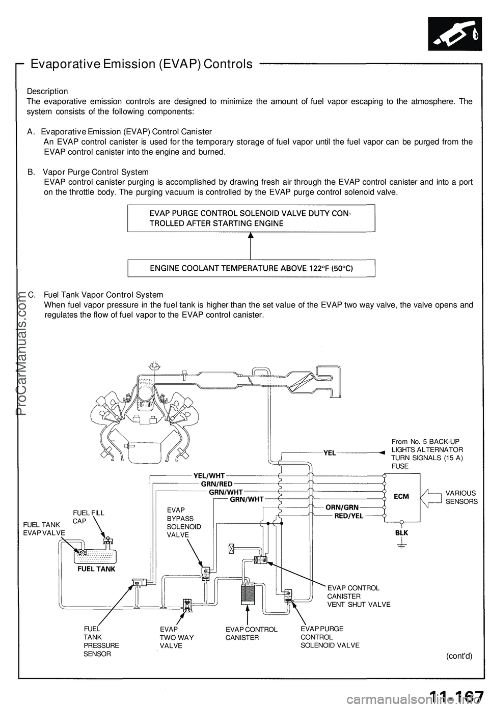
Evaporative Emission (EVAP) Controls
Description
The evaporative emission controls are designed to minimize the amount of fuel vapor escaping to the atmosphere. The
system consists of the following components:
A. Evaporative Emission (EVAP) Control Canister
An EVAP control canister is used for the temporary storage of fuel vapor until the fuel vapor can be purged from the
EVAP control canister into the engine and burned.
B. Vapor Purge Control System
EVAP control canister purging is accomplished by drawing fresh air through the EVAP control canister and into a port
on the throttle body. The purging vacuum is controlled by the EVAP purge control solenoid valve.
C. Fuel Tank Vapor Control System
When fuel vapor pressure in the fuel tank is higher than the set value of the EVAP two way valve, the valve opens and
regulates the flow of fuel vapor to the EVAP control canister.
From No. 5 BACK-UP
LIGHTS ALTERNATOR
TURN SIGNALS (15 A)
FUSE
FUEL TANK
EVAP VALVE
EVAP
BYPASS
SOLENOID
VALVE
VARIOUS
SENSORS
EVAP CONTROL
CANISTER
VENT SHUT VALVE
FUEL
TANK
PRESSURE
SENSOR
EVAP
TWO WAY
VALVE
EVAP CONTROL
CANISTER
EVAP PURGE
CONTROL
SOLENOID VALVE
(cont'd)
FUEL FILL
CAPProCarManuals.com
Page 1231 of 1503
Troubleshooting
Tips and Precautions
Before Troubleshooting
Check applicable fuses in the appropriate fuse box.
Check the battery for damage, state of charge, and
clean and tight connections.
Check the alternator belt tension.
CAUTION:
Do not quick-charge a battery unless the battery
ground cable has been disconnected.
Otherwise you will damage the alternator
diodes.
Do not attempt to crank the engine with the bat-
tery ground cable loosely connected or you will
severely damage the wiring.
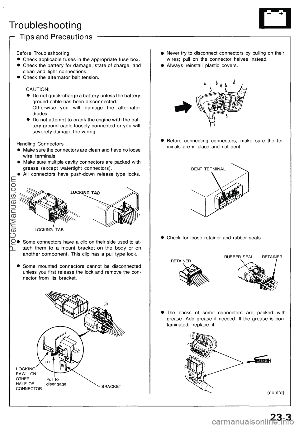
Handling Connectors
Make sure the connectors are clean and have no loose
wire terminals.
Make sure multiple cavity connectors are packed with
grease (except watertight connectors).
All connectors have push-down release type locks.
LOCKING TAB
Some connectors have a clip on their side used to at-
tach them to a mount bracket on the body or on
another component. This clip has a pull type lock.
Some mounted connectors cannot be disconnected
unless you first release the lock and remove the con-
nector from its bracket.
(21
LOCKING'
PAWL ON
OTHER
HALF OF
CONNECTOR
Pull to
disengage
BRACKET
Never try to disconnect connectors by pulling on their
wires; pull on the connector halves instead.
Always reinstall plastic covers.
Before connecting connectors, make sure the ter-
minals are in place and not bent.
BENT TERMINAL
Check for loose retainer and rubber seals.
RETAINER
RUBBER SEAL RETAINER
The backs of some connectors are packed with
grease. Add grease if needed. If the grease is con-
taminated, replace it.
(cont'd)ProCarManuals.com
Page 1270 of 1503
Charging Syste m
Troubleshootin g
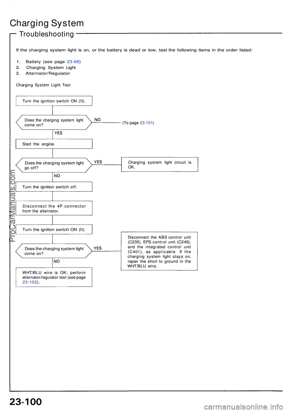
If th e chargin g syste m ligh t i s on , o r th e batter y i s dea d o r low , tes t th e followin g item s i n th e orde r listed :
1. Batter y (se e pag e 23-68 )
2 . Chargin g Syste m Ligh t
3 . Alternator/Regulato r
Charging Syste m Ligh t Tes t
Doe s th e chargin g syste m ligh t
com e on ?
Star t th e engine .
Does th e chargin g syste m ligh tgo off ?
Turn th e ignitio n switc h off .
Disconnec t th e 4 P connecto r
fro m th e alternator .
Turn th e ignitio n switc h O N (II) .
WHT/BL U wir e i s OK ; perfor m
alternator/regulato r tes t (se e pag e
23-102 ).
(T o page 23-101 )
Chargin g syste m ligh t circui t i s
OK .
Disconnec t th e AB S contro l uni t
(C235) , EP S contro l uni t (C249) ,
an d th e integrate d contro l uni t
(C401) , a s applicable . I f th e
chargin g syste m ligh t stay s on ,
repai r th e shor t t o groun d i n th e
WHT/BL U wire .
Does th e chargin g syste m ligh tcom e on ?
Tur
n th e ignitio n switc h O N (II) .
ProCarManuals.com
Page 1271 of 1503
(From page 23-100 )
I s th e fus e OK ?
Disconnec t th e 4 P connecto r
fro m th e alternator .
Tur n th e ignitio n switc h O N (II) .
Chec k fo r voltag e in th e YE L wir e
a t th e I G termina l o f th e 4 P con -
nector .
Is ther e batter y voltage ?
Groun d th e WHT/BL U wir e a t th e
L termina l o f th e 4 P connector .
Doe s th e chargin g syste m
light com e on ?
Perfor m alternator/regulato r tes t
(se e pag e 23-102 ). Replac
e th e fuse .
Repai r ope n in th e YE L wire .
Chec k fo r a blow n chargin g sys -
tem ligh t bulb . I f th e bul b is OK ,repai r ope n in th e WHT/BL U wire .
(cont'd )
Turn th e ignitio n switc h off .
Chec k fus e No . 2 (1 5 A) .
ProCarManuals.com
Page 1272 of 1503
Charging System
Troubleshooting (cont'd)
Alternator/Regulator Test
Use the SUN VAT-40 (or equivalent) tester.
LOAD ADJUSTER
(CARBON PILE)
FULL FIELD
LEAD (BLU)
VOLTMETER
NEGATIVE
LEAD (BLK)
INDUCTIVE
PICK-UP
(GRN)
POSITIVE
CABLE (RED)
NEGATIVE
CABLE (BLK)
VOLTMETER
POSITIVE
LEAD (RED)
1. Attach the positive tester cable and the voltmeter
positive lead to the jump start terminal in the
engine compartment fuse/relay box.
POSITIVE CABLE
VOLTMETER
POSITIVE LEAD
JUMP
START
TERMINAL
ENGINE COMPARTMENT
FUSE/RELAY BOX
2. Attach the negative tester cable and the voltmeter
negative lead to the top of the intake manifold.
VOLTMETER
NEGATIVE LEAD
NEGATIVE CABLE
NEGATIVE MARK
3. Attach the inductive pick-up to the B terminal wire
of the alternator with its arrow pointing away from
the terminal.
NOTE: The arrow must point away from the B
terminal.
INDUCTIVE PICK-UP
ARROW
ALTERNATOR
B TERMINAL
ALTERNATORProCarManuals.com
Page 1274 of 1503
Charging Syste m
Troubleshootin g (cont'd )
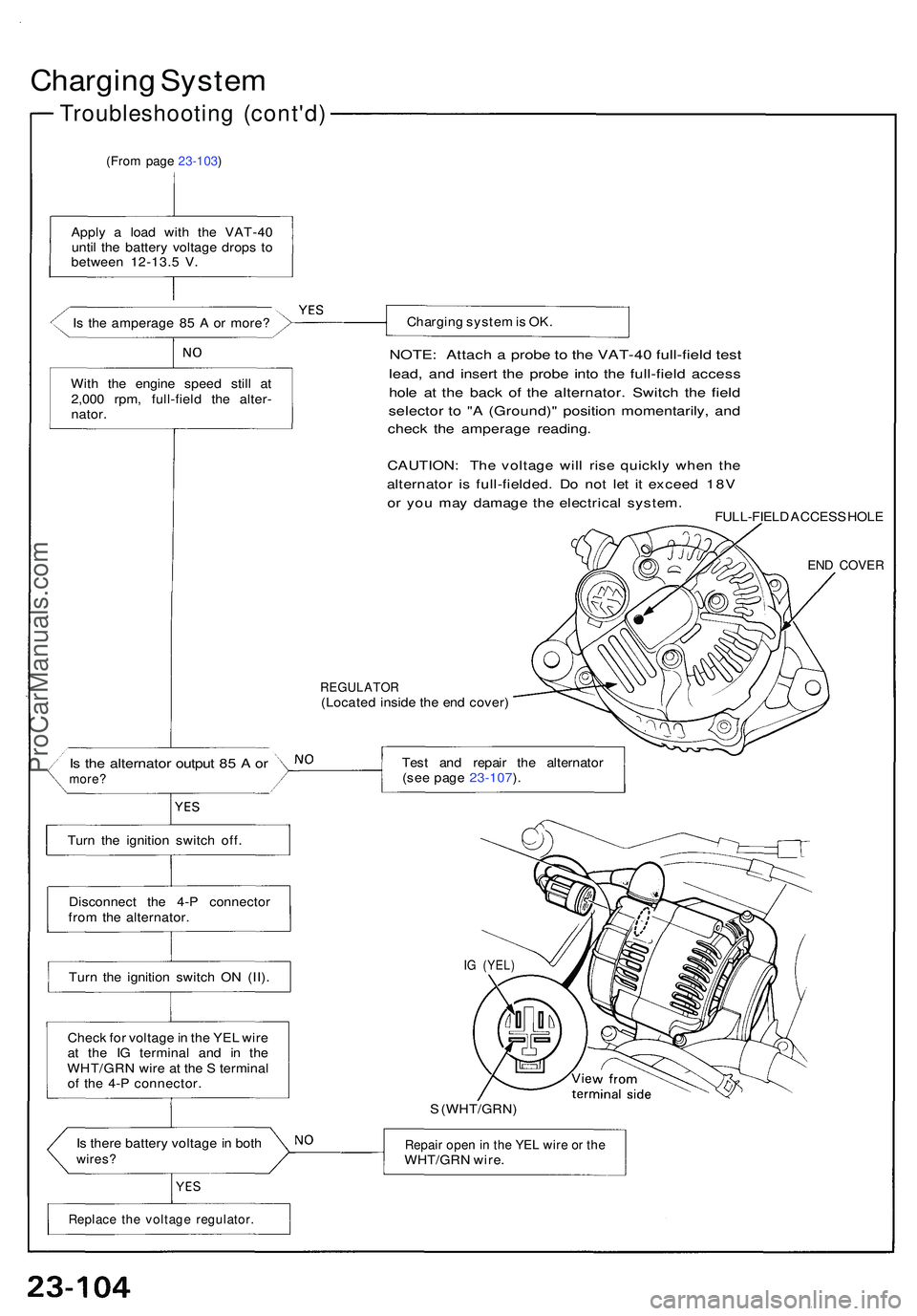
(From page 23-103 )
Apply a loa d wit h th e VAT-4 0
unti l th e batter y voltag e drop s t o
betwee n 12-13. 5 V .
I s th e amperag e 8 5 A or more ?
Wit h th e engin e spee d stil l a t
2,00 0 rpm , full-fiel d th e alter -
nator .
Tur n th e ignitio n switc h off .
Disconnec t th e 4- P connecto r
fro m th e alternator .
Tur n th e ignitio n switc h O N (II) .
Chec k fo r voltag e in th e YE L wir e
a t th e I G termina l an d i n th e
WHT/GR N wir e a t th e S termina l
o f th e 4- P connector .
I s ther e batter y voltag e in bot h
wires ?
Chargin g syste m is OK .
NOTE : Attac h a prob e to th e VAT-4 0 full-fiel d tes t
lead , an d inser t th e prob e int o th e full-fiel d acces s
hole a t th e bac k o f th e alternator . Switc h th e fiel d
selecto r t o " A (Ground) " positio n momentarily , an d
chec k th e amperag e reading .
CAUTION : Th e voltag e wil l ris e quickl y whe n th e
alternato r i s full-fielded . D o no t le t i t excee d 18 V
or yo u ma y damag e th e electrica l system .FULL-FIEL D ACCES S HOL E
END COVE R
REGULATO R(Located insid e th e en d cover )
Tes t an d repai r th e alternato r
(se e pag e 23-107 ).
IG (YEL )
S (WHT/GRN )
Repair ope n in th e YE L wir e o r th eWHT/GR N wire .
Is th e alternato r outpu t 8 5 A ormore ?
Replac e th e voltag e regulator .
ProCarManuals.com
Page 1275 of 1503
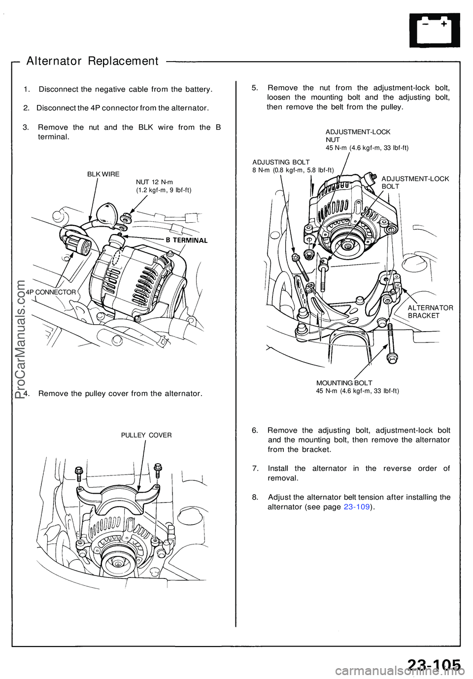
Alternator Replacemen t
1. Disconnec t th e negativ e cabl e fro m th e battery .
2 . Disconnec t th e 4 P connecto r fro m th e alternator .
3 . Remov e th e nu t an d th e BL K wir e fro m th e B
terminal .
BLK WIR ENUT 1 2 N- m(1.2 kgf-m , 9 Ibf-ft )
4P CONNECTO R
4. Remov e th e pulle y cove r fro m th e alternator .
PULLEY COVE R
5. Remov e th e nu t fro m th e adjustment-loc k bolt ,
loose n th e mountin g bol t an d th e adjustin g bolt ,
the n remov e th e bel t fro m th e pulley .
ADJUSTMENT-LOC KNUT45 N- m (4. 6 kgf-m , 3 3 Ibf-ft )
ADJUSTIN G BOL T8 N- m (0. 8 kgf-m , 5. 8 Ibf-ft )
ADJUSTMENT-LOC KBOLT
ALTERNATO RBRACKET
MOUNTIN G BOL T45 N- m (4. 6 kgf-m , 3 3 Ibf-ft )
6. Remov e th e adjustin g bolt , adjustment-loc k bol t
an d th e mountin g bolt , the n remov e th e alternato r
fro m th e bracket .
7 . Instal l th e alternato r i n th e revers e orde r o f
removal .
8. Adjus t th e alternato r bel t tensio n afte r installin g th e
alternato r (se e pag e 23-109 ).
ProCarManuals.com