1997 ACURA NSX turn signal bulb
[x] Cancel search: turn signal bulbPage 276 of 1503
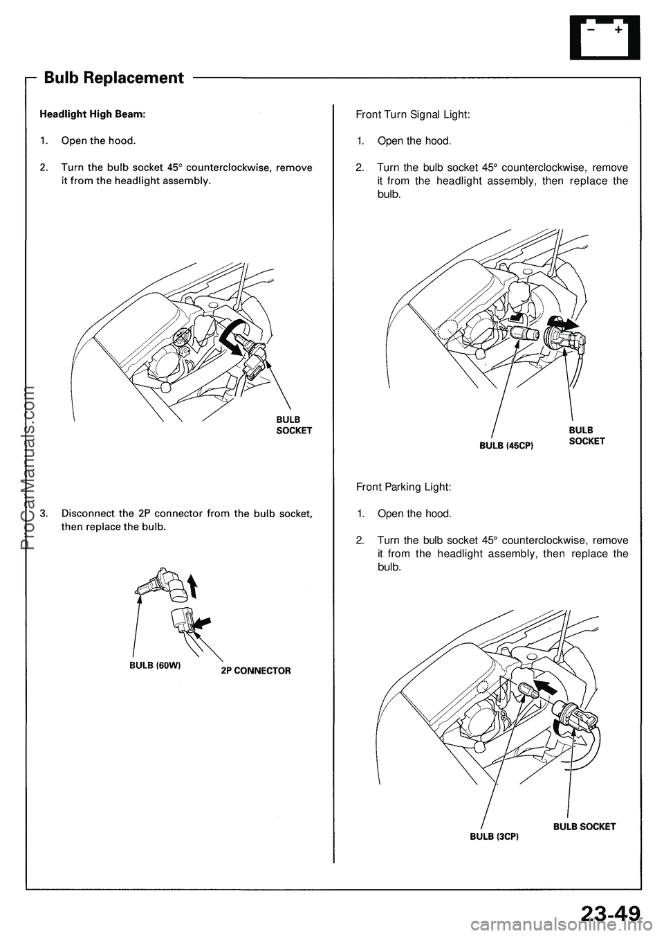
Front Turn Signal Light:
1. Open the hood.
2. Turn the bulb socket 45° counterclockwise, remove
it from the headlight assembly, then replace the
bulb.
Front Parking Light:
1. Open the hood.
2. Turn the bulb socket 45° counterclockwise, remove
it from the headlight assembly, then replace the
bulb.ProCarManuals.com
Page 586 of 1503
PGM-FI System
System Description (cont'd)
3. Fuel Cut-off Control
During deceleration with the throttle valve closed, current to the fuel injectors is cut off to improve fuel economy at
speeds over 1,500 rpm.
Fuel cut-off action also takes place when engine speed exceeds 8,300 rpm, regardless of the position of the throttle
valve, to protect the engine from over-revving.
4. A/C Compressor Clutch Relay
When the ECM receives a demand for cooling from the air conditioning system, it delays the compressor from being
energized, and enriches the mixture to assure smooth translation to the A/C mode.
5. Evaporative Emission (EVAP) Purge Control Solenoid Valve
When the engine coolant temperature is below 153°F (67°C), the ECM controls the EVAP purge control solenoid valve
which cuts vacuum to the EVAP purge control canister diaphragm.
6. Intake Air Bypass (IAB) Control Solenoid Valve
When the engine speed is below 4,800 rpm, the IAB control solenoid valve is activated by a signal from the ECM. Intake
air then flows through the smaller chamber, and high torque is delivered. To increase air flow at engine speeds higher
than 4,800 rpm, the solenoid valve is deactivated by the ECM, and the intake air flows through the larger chamber.
7. Exhaust Gas Recirculation (EGR) Control Solenoid Valve
When the EGR is required for control of oxides of nitrogen (NOx) emissions, the ECM supplies ground to the EGR
control solenoid valve which supplies regulated vacuum to the EGR valve.
ECM Fail-safe/Back-up Functions
1. Fail-Safe Function
When an abnormality occurs in a signal from a sensor, the ECM ignores that signal and assumes a pre-programmed
valve for that sensor that allows the engine to continue to run.
2. Back-up Function
When an abnormality occurs in the ECM itself, the fuel injectors are controlled by a back-up circuit independent of the
system in order to permit minimal driving.
3. Self-diagnosis Function [Malfunction Indicator Lamp (MIL)]
When an abnormality occurs in a signal from a sensor, the ECM lights the MIL and stores the diagnostic trouble code
in erasable memory. When the ignition is initially turned on, the ECM supplies ground for the MIL for two seconds to
check the MIL bulb condition.
4. Two Trip Detection Method
To prevent false indications, the Two Trip Detection Method is used for the H02S, fuel metering-related, idle control
system, ECT sensor, EGR system self-diagnostic functions and EVAP control system. When an abnormality occurs,
the ECM stores it in its memory. When the same abnormality recurs after the ignition switch is turned OFF and ON (II)
again, the ECM informs the driver by lighting the MIL.
However, to ease troubleshooting, this function is cancelled when you short the service check connector. The MIL will
then blink immediately when an abnormality occurs.
5. Two (or three) Driving Cycle Detection Method
A "Driving Cycle" consists of starting the engine, beginning closed loop operation, and stopping the engine. If misfir-
ing that increases emissions or EVAP control system malfunction is detected during two consecutive driving cycles,
or TWC deterioration is detected during three consecutive driving cycles, the ECM turns the MIL on.
However,
to
ease
troubleshooting,
this
function
is
cancelled when
you
short
the
service check connector.
The MIL
will
then blink immediately when an abnormality occurs.ProCarManuals.com
Page 587 of 1503
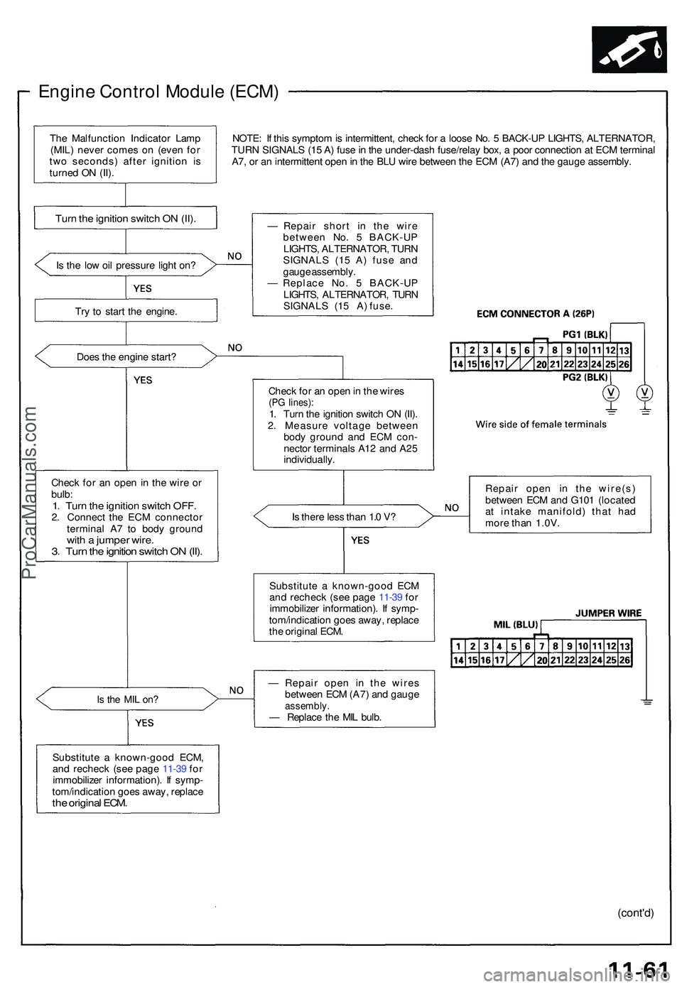
Engine Contro l Modul e (ECM )
NOTE: I f thi s sympto m is intermittent , chec k fo r a loos e No . 5 BACK-U P LIGHTS , ALTERNATOR ,
TUR N SIGNAL S (1 5 A ) fus e in th e under-das h fuse/rela y box , a poo r connectio n a t EC M termina l
A7 , o r a n intermitten t ope n in th e BL U wir e betwee n th e EC M (A7 ) an d th e gaug e assembly .
I s th e lo w oi l pressur e ligh t on ?
Tr y t o star t th e engine .
Doe s th e engin e start ?
Chec k fo r a n ope n in th e wir e o r
bulb :
1. Tur n th e ignitio n switc h OFF .2. Connec t th e EC M connecto r
termina l A 7 t o bod y groun d
with a jumpe r wire .3. Tur n th e ignitio n switc h O N (II) .
Is th e MI L on ?
Substitut e a known-goo d ECM ,
an d rechec k (se e pag e 11-3 9 fo r
immobilize r information) . I f symp -
tom/indicatio n goe s away , replac e
the origina l ECM .
— Repai r shor t i n the wir e
betwee n No . 5 BACK-U P
LIGHTS , ALTERNATOR , TUR N
SIGNAL S (1 5 A ) fus e an d
gaug e assembly .
— Replac e No . 5 BACK-U P
LIGHTS , ALTERNATOR , TUR N
SIGNALS (15 A) fuse.
Chec k fo r a n ope n in th e wire s
(PG lines) :1. Tur n th e ignitio n switc h O N (II) .
2 . Measur e voltag e betwee n
bod y groun d an d EC M con -
necto r terminal s A1 2 an d A2 5
individually .
I s ther e les s tha n 1. 0 V ?
Substitut e a known-goo d EC M
an d rechec k (se e pag e 11-3 9 fo r
immobilize r information) . I f symp -
tom/indicatio n goe s away , replac e
th e origina l ECM . Repai
r ope n i n th e wire(s )
betwee n EC M an d G10 1 (locate d
a t intak e manifold ) tha t ha d
mor e tha n 1.0V .
— Repai r ope n i n th e wire s
betwee n EC M (A7 ) an d gaug e
assembly .— Replac e th e MI L bulb .
(cont'd )
Turn th e ignitio n switc h O N (II) .
The Malfunctio n Indicato r Lam p
(MIL ) neve r come s o n (eve n fo r
tw o seconds ) afte r ignitio n i s
turne d O N (II) .
ProCarManuals.com
Page 1292 of 1503
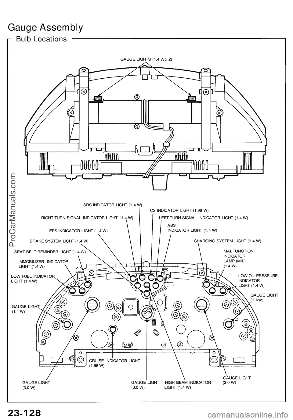
Gauge Assembly
Bulb Locations
GAUGE LIGHTS (1.4 Wx 2)
SRS INDICATOR LIGHT (1.4 W)
RIGHT TURN SIGNAL INDICATOR LIGHT 11.4 W)
EPS INDICATOR LIGHT (1.4 W)
BRAKE SYSTEM LIGHT (1.4 W)
SEAT BELT REMINDER LIGHT (1.4 W)
IMMOBILIZER INDICATOR
LIGHT (1.4 W)
LOW FUEL INDICATOR
LIGHT (1.4 W)
GAUGE LIGHT
(1.4
W)
TCS INDICATOR LIGHT (1.96 W)
LEFT TURN SIGNAL INDICATOR LIGHT (1.4 W)
ABS
INDICATOR LIGHT (1.4 W)
CHARGING SYSTEM LIGHT (1.4 W)
MALFUNCTION
INDICATOR
LAMP (MIL)
(1.4
W)
CRUISE INDICATOR LIGHT
(1.96
W)
LOW OIL PRESSURE
INDICATOR
LIGHT (1.4 W)
GAUGE LIGHT
.4W)
GAUGE LIGHT
(3.0
W)
GAUGE LIGHT
GAUGE LIGHT HIGH BEAM INDICATOR (3.0 W)
(3.0 W) LIGHT (1.4 W)ProCarManuals.com
Page 1336 of 1503
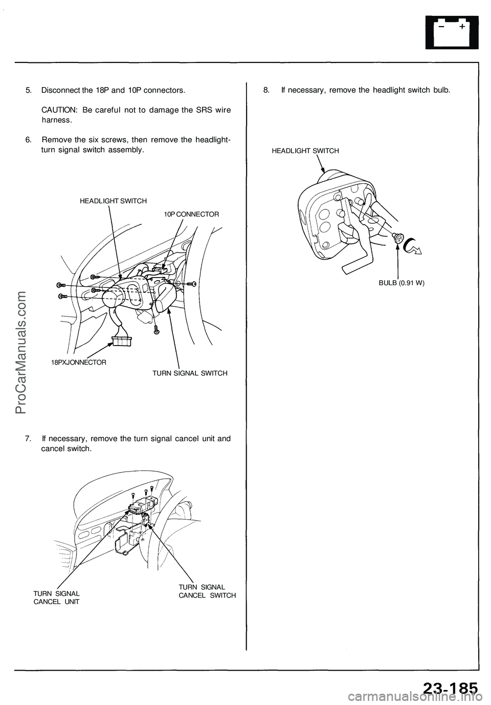
5. Disconnect the 18P and 10P connectors.
CAUTION: Be careful not to damage the SRS wire
harness.
6. Remove the six screws, then remove the headlight-
turn signal switch assembly.
HEADLIGHT SWITCH
10P CONNECTOR
18PXJONNECTOR
TURN SIGNAL SWITCH
7. If necessary, remove the turn signal cancel unit and
cancel switch.
TURN SIGNAL
CANCEL UNIT
TURN SIGNAL
CANCEL SWITCH
8. If necessary, remove the headlight switch bulb.
HEADLIGHT SWITCH
BULB (0.91 W)ProCarManuals.com
Page 1350 of 1503
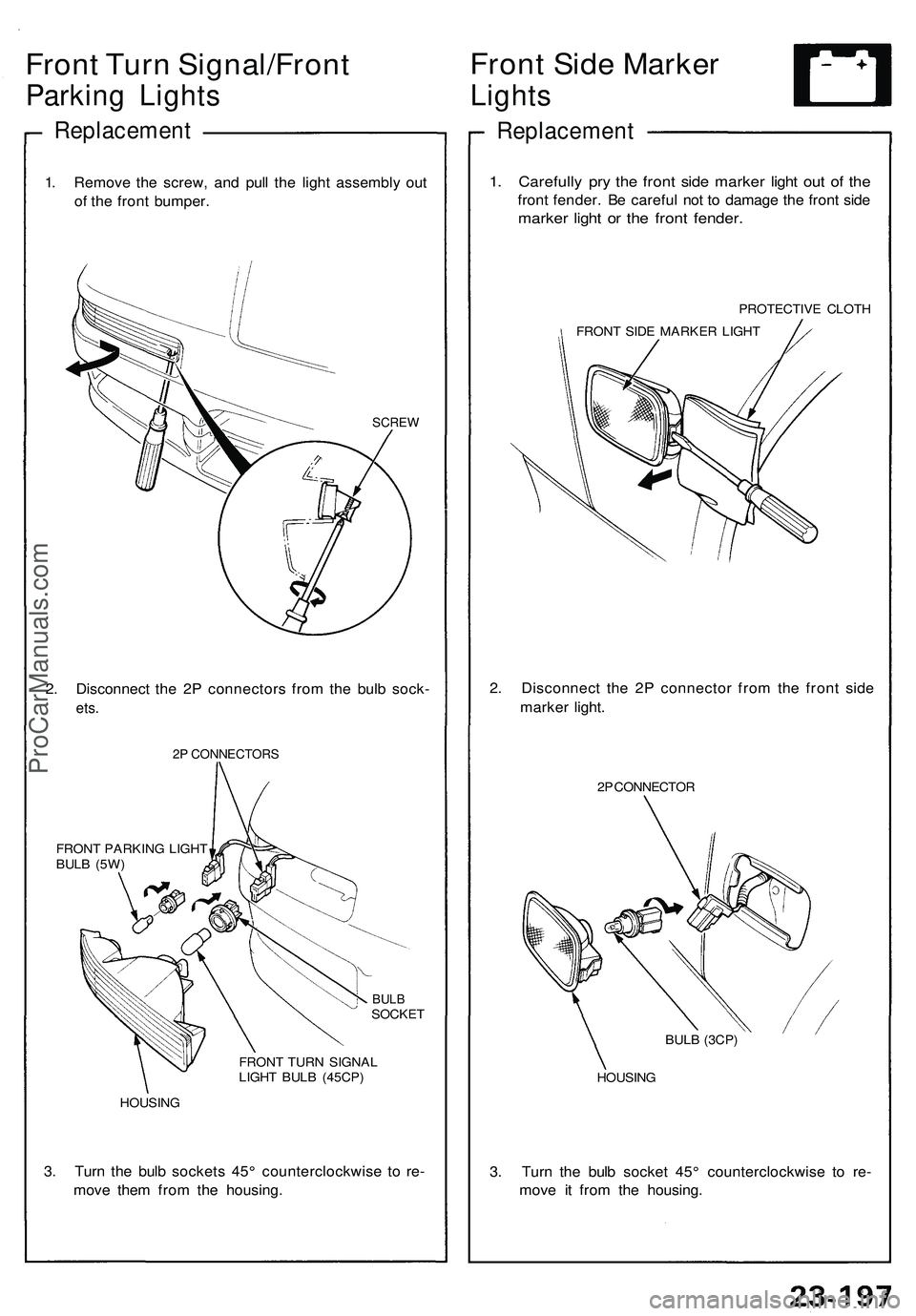
Front Turn Signal/Front
Parking Lights
Replacement
1. Remove the screw, and pull the light assembly out
of the front bumper.
SCREW
2. Disconnect the 2P connectors from the bulb sock-
ets.
2P CONNECTORS
FRONT PARKING LIGHT
BULB (5W)
BULB
SOCKET
FRONT TURN SIGNAL
LIGHT BULB (45CP)
HOUSING
3. Turn the bulb sockets 45° counterclockwise to re-
move them from the housing.
Front Side Marker
Lights
Replacement
1. Carefully pry the front side marker light out of the
front fender. Be careful not to damage the front side
marker light or the front fender.
PROTECTIVE CLOTH
FRONT SIDE MARKER LIGHT
2. Disconnect the 2P connector from the front side
marker light.
2P CONNECTOR
HOUSING
3. Turn the bulb socket 45° counterclockwise to re-
move it from the housing.
BULB (3CP)ProCarManuals.com
Page 1351 of 1503
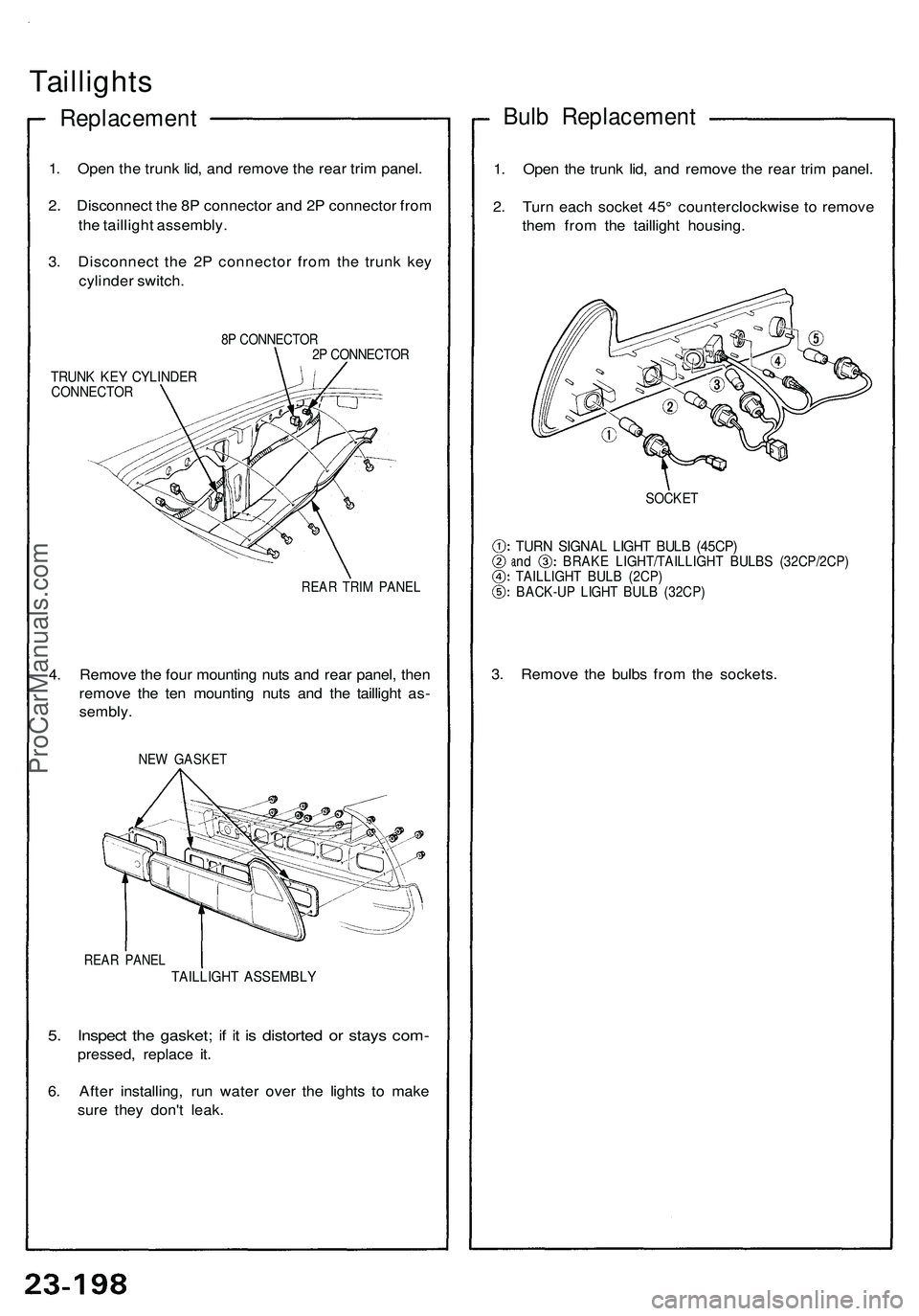
Taillights
Replacement
1. Open the trunk lid, and remove the rear trim panel.
2. Disconnect the 8P connector and 2P connector from
the taillight assembly.
3. Disconnect the 2P connector from the trunk key
cylinder switch.
8P CONNECTOR
2P CONNECTOR
TRUNK KEY CYLINDER
CONNECTOR
REAR TRIM PANEL
4. Remove the four mounting nuts and rear panel, then
remove the ten mounting nuts and the taillight as-
sembly.
NEW GASKET
REAR PANEL
TAILLIGHT ASSEMBLY
5. Inspect the gasket; if it is distorted or stays com-
pressed, replace it.
6. After installing, run water over the lights to make
sure they don't leak.
Bulb Replacement
1. Open the trunk lid, and remove the rear trim panel.
2. Turn each socket 45° counterclockwise to remove
them from the taillight housing.
SOCKET
TURN SIGNAL LIGHT BULB (45CP)
and BRAKE LIGHT/TAILLIGHT BULBS (32CP/2CP)
TAILLIGHT BULB (2CP)
BACK-UP LIGHT BULB (32CP)
3. Remove the bulbs from the sockets.ProCarManuals.com
Page 1368 of 1503
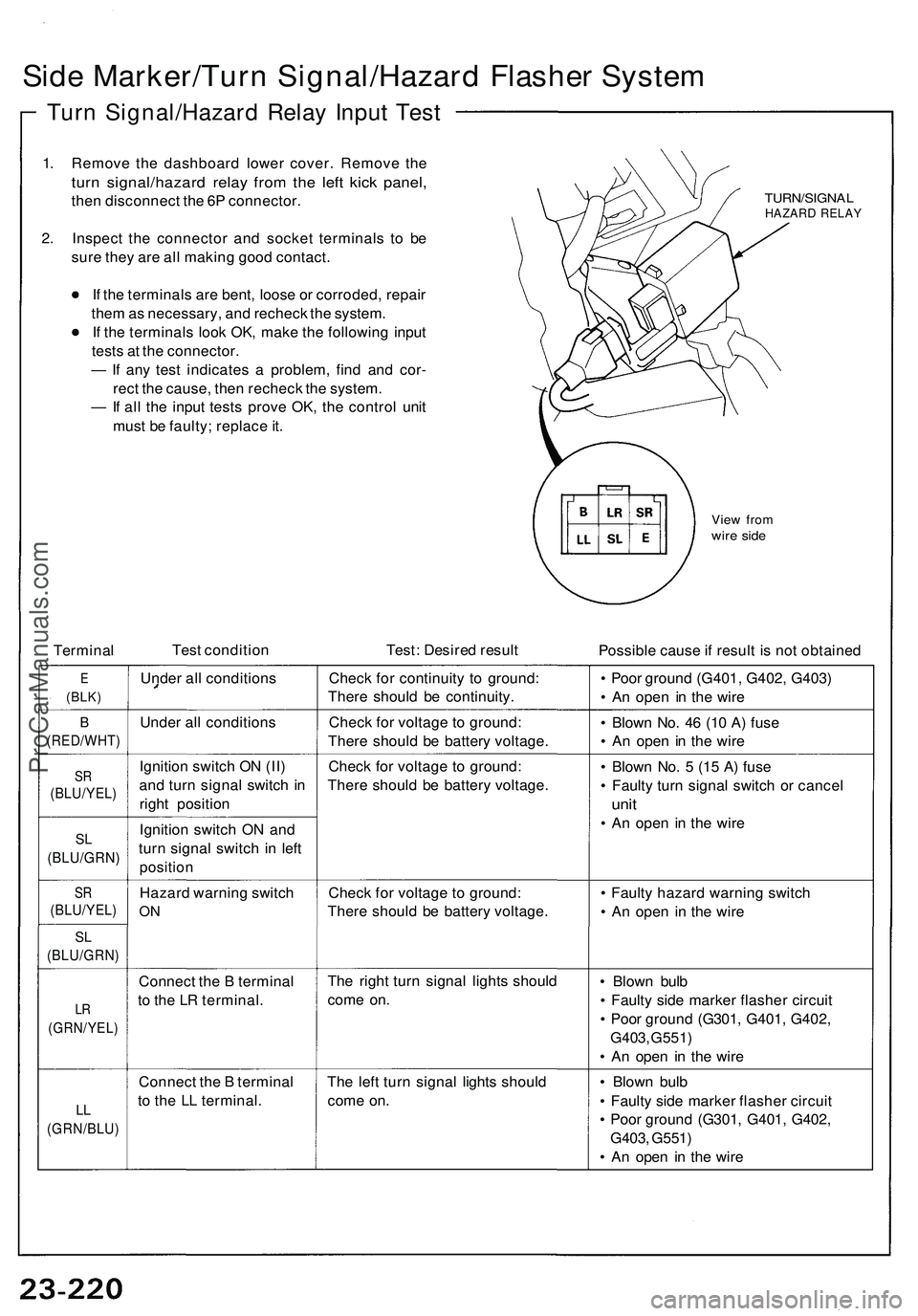
Side Marker/Turn Signal/Hazard Flasher System
Turn Signal/Hazard Relay Input Test
1. Remove the dashboard lower cover. Remove the
turn signal/hazard relay from the left kick panel,
then disconnect the 6P connector.
2. Inspect the connector and socket terminals to be
sure they are all making good contact.
If the terminals are bent, loose or corroded, repair
them as necessary, and recheck the system.
If the terminals look OK, make the following input
tests at the connector.
— If any test indicates a problem, find and cor-
rect the cause, then recheck the system.
— If all the input tests prove OK, the control unit
must be faulty; replace it.
TURN/SIGNAL
HAZARD RELAY
View from
wire side
Terminal
Test condition
Test: Desired result
Possible cause if result is not obtained
E
(BLK)
Under all conditions
Check for continuity to ground:
There should be continuity.
• Poor ground (G401, G402, G403)
• An open in the wire
B
(RED/WHT)
Under all conditions
Check for voltage to ground:
There should be battery voltage.
• Blown No. 46 (10 A) fuse
• An open in the wire
SR
(BLU/YEL)
Ignition switch ON (II)
and turn signal switch in
right position
Check for voltage to ground:
There should be battery voltage.
SL
(BLU/GRN)
Ignition switch ON and
turn signal switch in left
position
• Blown No. 5 (15 A) fuse
• Faulty turn signal switch or cancel
unit
• An open in the wire
SR
(BLU/YEL)
Hazard warning switch
ON
Check for voltage to ground:
There should be battery voltage.
SL
(BLU/GRN)
LR
(GRN/YEL)
Connect the B terminal
to the LR terminal.
The right turn signal lights should
come on.
• Blown bulb
• Faulty side marker flasher circuit
• Poor ground (G301, G401, G402,
G403, G551)
• An open in the wire
LL
(GRN/BLU)
Connect the B terminal
to the LL terminal.
The left turn signal lights should
come on.
• Blown bulb
• Faulty side marker flasher circuit
• Poor ground (G301, G401, G402,
G403, G551)
• An open in the wire
• Faulty hazard warning switch
• An open in the wireProCarManuals.com