Page 130 of 1503
II. Engine Control Module (ECM) Reset Procedure
Either of the following actions, will reset the ECM.
• Using the OBD II scan tool or Honda PGM Tester to clear the ECM's memory.
NOTE: See the OBD II scan tool or Honda PGM Tester user's manuals for specific operating instructions.
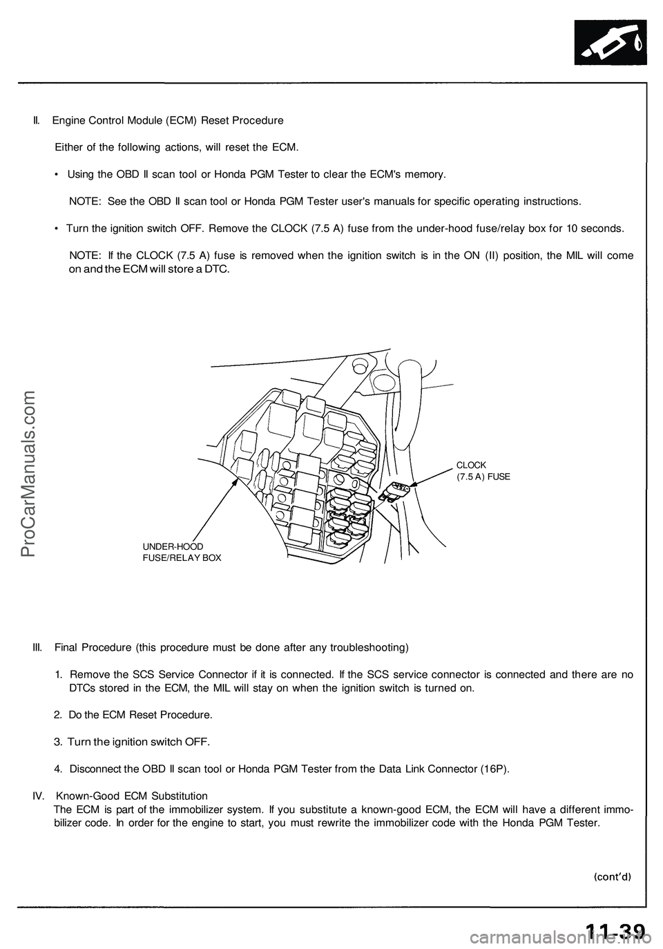
• Turn the ignition switch OFF. Remove the CLOCK (7.5 A) fuse from the under-hood fuse/relay box for 10 seconds.
NOTE: If the CLOCK (7.5 A) fuse is removed when the ignition switch is in the ON (II) position, the MIL will come
on and the ECM will store a DTC.
UNDER-HOOD
FUSE/RELAY BOX
CLOCK
(7.5 A) FUSE
III. Final Procedure (this procedure must be done after any troubleshooting)
1. Remove the SCS Service Connector if it is connected. If the SCS service connector is connected and there are no
DTCs stored in the ECM, the MIL will stay on when the ignition switch is turned on.
2. Do the ECM Reset Procedure.
3. Turn the ignition switch OFF.
4. Disconnect the OBD II scan tool or Honda PGM Tester from the Data Link Connector (16P).
IV. Known-Good ECM Substitution
The ECM is part of the immobilizer system. If you substitute a known-good ECM, the ECM will have a different immo-
bilizer code. In order for the engine to start, you must rewrite the immobilizer code with the Honda PGM Tester.ProCarManuals.com
Page 565 of 1503
Engine Control Module (ECM) Reset Procedure
Either of the following actions, will reset the ECM.
Using the OBD II scan tool or Honda PGM Tester to clear the ECM's memory.
NOTE: See the OBD II scan tool or Honda PGM Tester user's manuals for specific operating instructions.
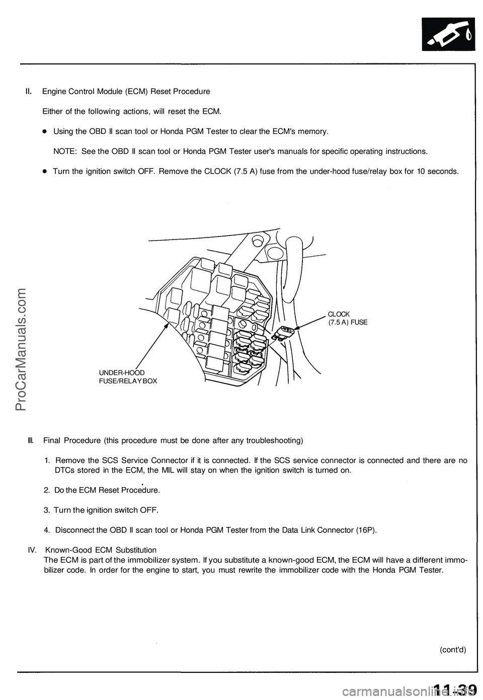
Turn the ignition switch OFF. Remove the CLOCK (7.5 A) fuse from the under-hood fuse/relay box for 10 seconds.
UNDER-HOOD
FUSE/RELAY BOX
CLOCK
(7.5 A) FUSE
III. Final Procedure (this procedure must be done after any troubleshooting)
1. Remove the SCS Service Connector if it is connected. If the SCS service connector is connected and there are no
DTCs stored in the ECM, the MIL will stay on when the ignition switch is turned on.
2. Do the ECM Reset Procedure.
3. Turn the ignition switch OFF.
4. Disconnect the OBD II scan tool or Honda PGM Tester from the Data Link Connector (16P).
IV. Known-Good ECM Substitution
The ECM is part of the immobilizer system. If you substitute a known-good ECM, the ECM will have a different immo-
bilizer code. In order for the engine to start, you must rewrite the immobilizer code with the Honda PGM Tester.
(cont'd)ProCarManuals.com
Page 576 of 1503
Troubleshooting
Engine Control Module Terminal Arrangement (cont'd)
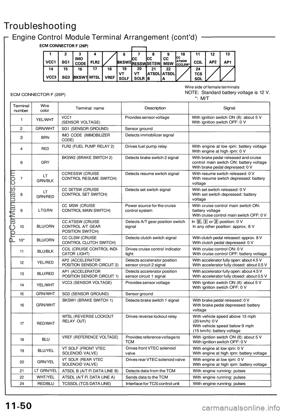
ECM CONNECTOR F (26P)
Wire side of female terminals
NOTE: Standard battery voltage is 12 V.
*: M/T
Terminal
number
1
2
3
4
6
7
8
9
10
10*
11
12
13
14
15
16
17
18
19
20
21
22
24
Wire
color
YEL/WHT
GRN/WHT
BRN
RED
GRY
LT
GRN/BLK
LT
GRN/RED
LTGRN
BLU/ORN
BLU/ORN
BLU/BLK
YEL/RED
BLU/RED
YEL/WHT
GRN/WHT
GRN/WHT
RED/WHT
BLU
BLU/YEL
GRN/YEL
LT GRN/YEL
WHT/YEL
RED/BLU
Terminal name
VCC1
(SENSOR VOLTAGE)
SG1 (SENSOR GROUND)
IMO CODE (IMMOBILIZER
CODE)
FLR2 (FUEL PUMP RELAY 2)
BKSW2 (BRAKE SWITCH 2)
CCRESSW (CRUISE
CONTROL RESUME SWITCH)
CC SETSW (CRUISE
CONTROL SET SWITCH)
CC MSW (CRUISE
CONTROL MAIN SWITCH)
CC ATSSW (CRUISE
CONTROL A/T GEAR
POSITION SWITCH)
CC CLSW (CRUISE
CONTROL CLUTCH SWITCH)
CCIL (CRUISE CONTROL INDI-
CATOR LIGHT)
AP2 (ACCELERATOR
POSITION SENSOR CIRCUIT 2)
AP1 (ACCELERATOR
POSITION SENSOR CIRCUIT 1)
VCC3 (SENSOR VOLTAGE)
SG3 (SENSOR GROUND)
BKSW1 (BRAKE SWITCH 1)
MTSL (REVERSE LOCKOUT
RELAY OUT)
VREF (REFERENCE VOLTAGE)
VT SOLF (FRONT VTEC
SOLENOID VALVE)
VT SOLR (REAR VTEC
SOLENOID VALVE)
ATSDL B (A/T Fl DATA LINE B)
ATSDL (A/T Fl. DATA LINE A)
TCSSDL (TCS DATA LINE)
Description
Provides sensor voltage
Sensor ground
Detects immobilizer signal
Drives fuel pump relay
Detects brake switch 2 signal
Detects resume switch signal
Detects set switch signal
Power source for the cruise
control system
Detects A/T gear position switch
signal
Detects clutch switch signal
Drives cruise control indicator
light
Detects accelerator position
sensor circuit 2 signal
Detects accelerator position
sensor circuit 1 signal
Provides sensor voltage
Sensor ground
Detects brake switch 1 signal
Drives reverse lockout relay
Provides reference voltage to
TCM
Drives front VTEC solenoid
valve
Drives rear VTEC solenoid valve
Detects data from the TCM
Sends data to the TCM
Interface for TCS control unit
Signal
With ignition switch ON (II): about 5 V
With ignition switch OFF: 0 V
With engine at low rpm: battery voltage
With engine at high rpm: 0 V
With brake pedal released and cruise
control main switch ON: battery voltage
With brake pedal depressed: 0 V
With resume switch released: 0 V
With resume switch depressed: battery
voltage
With set switch released: 0 V
With set switch depressed: battery
voltage
With cruise control main switch ON:
battery voltage
With cruise control main switch OFF: 0 V
In , or position: 0 V
In any other position: approx. 8 V
With clutch pedal released: approx. 8 V
With clutch pedal depressed: 0 V
With cruise control ON: 0 V
With cruise control OFF: battery voltage
With accelerator fully open: about 4.5 V
With accelerator fully closed: about 0.5 V
With accelerator fully open: about 4.5 V
With accelerator fully closed: about 0.5 V
With ignition switch ON (II): about 5 V
With ignition switch OFF: 0 V
With brake pedal released: 0 V
With brake pedal depressed: battery
voltage
With vehicle speed above 13 mph
(20 km/h): 0 V
With vehicle speed below 9 mph
(15 km/h): battery voltage
With ignition switch ON (II): about 5 V
With ignition switch OFF: 0 V
With engine at low rpm: 0 V
With engine at high rpm: battery voltage
With engine at low rpm: 0 V
With engine at high rpm: battery voltage
With engine running: pulses
With engine running: pulses
With engine running: pulsesProCarManuals.com
Page 1235 of 1503
Relay and Control Unit Locations
Dashboard
IMMOBILIZER CONTROL UNIT
CLIMATE CONTROL UNIT
TURN SIGNAL/HAZARD
RELAY
DASHBOARD
LOWER COVER
INTEGRATED
CONTROL UNIT
UNDER-DASH FUSE BOXProCarManuals.com
Page 1247 of 1503
Ignition Switch
Steering Lock Removal/Installation (cont'd)
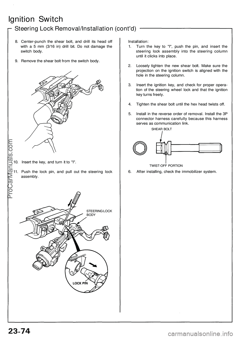
8. Center-punch the shear bolt, and drill its head off
with a 5 mm (3/16 in) drill bit. Do not damage the
switch body.
9. Remove the shear bolt from the switch body.
10. Insert the key, and turn it to "I".
11. Push the lock pin, and pull out the steering lock
assembly.
STEERING LOCK
BODY
Installation:
1. Turn the key to "I", push the pin, and insert the
steering lock assembly into the steering column
until it clicks into place.
2. Loosely tighten the new shear bolt. Make sure the
projection on the ignition switch is aligned with the
hole in the steering column.
3. Insert the ignition key, and check for proper opera-
tion of the steering wheel lock and that the ignition
key turns freely.
4. Tighten the shear bolt until the hex head twists off.
5. Install in the reverse order of removal. Install the 3P
connector harness carefully because this harness
serves as communication link.
SHEAR BOLT
TWIST-OFF PORTION
6. After installing, check the immobilizer system.ProCarManuals.com
Page 1292 of 1503
Gauge Assembly
Bulb Locations
GAUGE LIGHTS (1.4 Wx 2)
SRS INDICATOR LIGHT (1.4 W)
RIGHT TURN SIGNAL INDICATOR LIGHT 11.4 W)
EPS INDICATOR LIGHT (1.4 W)
BRAKE SYSTEM LIGHT (1.4 W)
SEAT BELT REMINDER LIGHT (1.4 W)
IMMOBILIZER INDICATOR
LIGHT (1.4 W)
LOW FUEL INDICATOR
LIGHT (1.4 W)
GAUGE LIGHT
(1.4
W)
TCS INDICATOR LIGHT (1.96 W)
LEFT TURN SIGNAL INDICATOR LIGHT (1.4 W)
ABS
INDICATOR LIGHT (1.4 W)
CHARGING SYSTEM LIGHT (1.4 W)
MALFUNCTION
INDICATOR
LAMP (MIL)
(1.4
W)
CRUISE INDICATOR LIGHT
(1.96
W)
LOW OIL PRESSURE
INDICATOR
LIGHT (1.4 W)
GAUGE LIGHT
.4W)
GAUGE LIGHT
(3.0
W)
GAUGE LIGHT
GAUGE LIGHT HIGH BEAM INDICATOR (3.0 W)
(3.0 W) LIGHT (1.4 W)ProCarManuals.com
Page 1465 of 1503
Immobilizer Syste m
Componen t Locatio n Inde x
IMMOBILIZE R INDICATO R LIGH T
(I n th e gaug e assembly )
Bul b Locations , pag e 23-12 8
CLUTC H INTERLOC K SWITC H
(M/T)Test, pag e 23-8 0
IMMOBILIZE R CONTRO L
UNITInpu t Test , pag e23-33 4
IMMOBILIZE R RECEIVE R
Test , pag e 23-33 5
Replacement , pag e 23-33 6
A/T GEA R POSITIO N
SWITC H
Test , pag e 23-16 2
STARTE R CU T RELA YWire colors : BLK/WHT ,
BLK/WHT , BLK/GRN ,
an d BLK/BL U
Test , pag e 23-8 0
TRANSPONDE R(Built int o th e ignitio n key )Test , pag e 23-33 5
IGNITIO N KEY(Maste r an d vale t keys )
ProCarManuals.com
Page 1466 of 1503
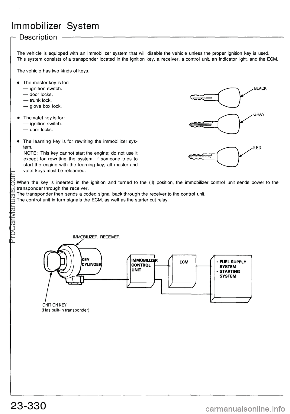
Immobilizer Syste m
Descriptio n
The vehicl e i s equippe d wit h a n immobilize r syste m tha t wil l disabl e th e vehicl e unles s th e prope r ignitio n ke y i s used .
Thi s syste m consist s o f a transponde r locate d i n th e ignitio n key , a receiver , a contro l unit , a n indicato r light , an d th e ECM .
Th e vehicl e ha s tw o kind s o f keys .
BLAC K
GRAY
The maste r ke y i s for :
— ignitio n switch .
— doo r locks .
— trun k lock .
— glov e bo x lock .
Th e vale t ke y i s for :
— ignitio n switch .
— doo r locks .
Th e learnin g ke y i s fo r rewritin g th e immobilize r sys -
tem.
NOTE : Thi s ke y canno t star t th e engine ; d o no t us e i t
excep t fo r rewritin g th e system . I f someon e trie s t o
star t th e engin e wit h th e learnin g key , al l maste r an d
vale t key s mus t b e relearned .
Whe n th e ke y i s inserte d i n th e ignitio n an d turne d t o th e (II ) position , th e immobilize r contro l uni t send s powe r t o th e
transponde r throug h th e receiver .
Th e transponde r the n send s a code d signa l bac k throug h th e receive r t o th e contro l unit .
Th e contro l uni t i n tur n signal s th e ECM , a s wel l a s th e starte r cu t relay .
RED
IMMOBILIZE R RECEIVE R
IGNITION KE Y(Has built-i n transponder )
23-330ProCarManuals.com