Page 130 of 1503

II. Engine Control Module (ECM) Reset Procedure
Either of the following actions, will reset the ECM.
• Using the OBD II scan tool or Honda PGM Tester to clear the ECM's memory.
NOTE: See the OBD II scan tool or Honda PGM Tester user's manuals for specific operating instructions.
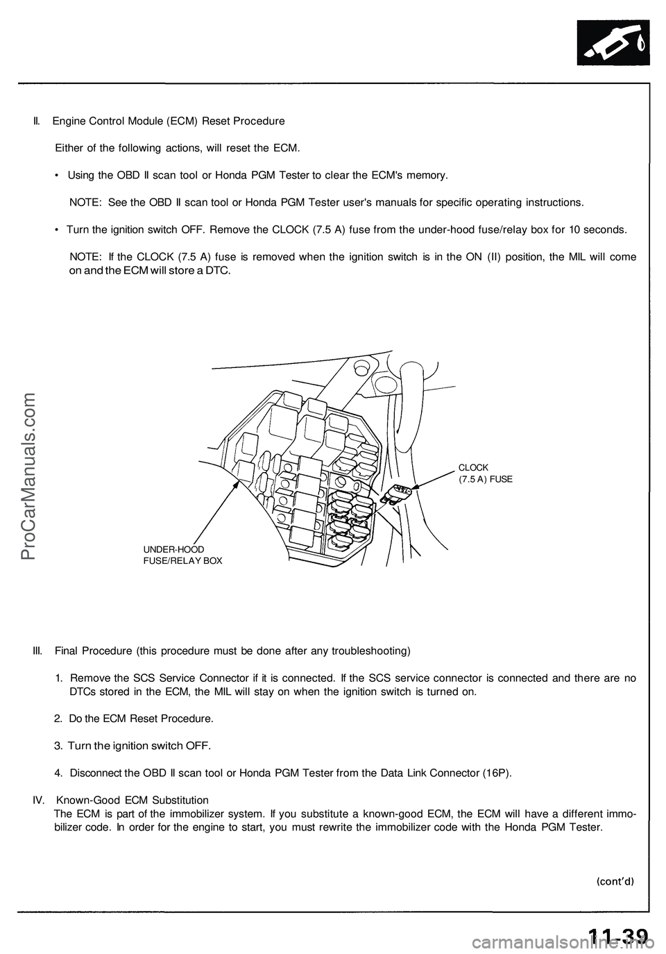
• Turn the ignition switch OFF. Remove the CLOCK (7.5 A) fuse from the under-hood fuse/relay box for 10 seconds.
NOTE: If the CLOCK (7.5 A) fuse is removed when the ignition switch is in the ON (II) position, the MIL will come
on and the ECM will store a DTC.
UNDER-HOOD
FUSE/RELAY BOX
CLOCK
(7.5 A) FUSE
III. Final Procedure (this procedure must be done after any troubleshooting)
1. Remove the SCS Service Connector if it is connected. If the SCS service connector is connected and there are no
DTCs stored in the ECM, the MIL will stay on when the ignition switch is turned on.
2. Do the ECM Reset Procedure.
3. Turn the ignition switch OFF.
4. Disconnect the OBD II scan tool or Honda PGM Tester from the Data Link Connector (16P).
IV. Known-Good ECM Substitution
The ECM is part of the immobilizer system. If you substitute a known-good ECM, the ECM will have a different immo-
bilizer code. In order for the engine to start, you must rewrite the immobilizer code with the Honda PGM Tester.ProCarManuals.com
Page 271 of 1503
Lighting System
HID Lamp System Troubleshooting
1. Check the No. 49 (20 A) or No. 52 (20 A) fuse in the
main under-hood fuse/relay box.
Are the fuses OK?
YES — Go to step 2.
NO — Replace the fuse (s), and recheck.
2. Substitute a known-good HID bulb and recheck.
Does the headlight low beam come on?
YES — Replace the HID bulb.
NO — Go to step 3.
3. Disconnect the 2P connector from the inverter unit.
4. Turn the combination light switch ON.
5. Measure the voltage between the No. 2 terminal of
the inverter unit 2P connector and body ground.
7. Check for continuity between the No. 1 terminal of
the inverter unit 2P connector and body ground.
Is there continuity?
YES — Substitute a known-good inverter, and
recheck. If the symptom/indication goes away,
replace the original inverter unit.
NO — Repair open in the wire between the inverter
unit and body ground. If the wire is OK, check for
poor ground at G202 or G302.ProCarManuals.com
Page 272 of 1503
Headlight Low Beam Relay Test
1. Remove the headlight low beam relay from the
under-hood fuse/relay box.
2. Check continuity at the relay terminals.
• There should be continuity between the C and D
terminals.
• There should be continuity between the A and B
terminals when power and ground are connect-
ed to the C and D terminals.
• There should be no continuity between the A
and B terminals when power is disconnected.
Headlight High Beam/Dimmer
Relay (USA) Test
1. Remove the headlight high beam relay or the dimmer
relay (USA) from the under-hood fuse/relay box.
2. Check continuity at the relay terminals.
• There should be continuity between the C and D
terminals.
• There should be continuity between the A and B
terminals when power and ground are connect-
ed to the C and D terminals.
• There should be no continuity between the A and
B terminals when power is disconnected.
• Headlight high beam relay
• Dimmer relay (USA)ProCarManuals.com
Page 352 of 1503
Symptom-to-Component Char t
Electrica l Syste m (cont'd )
If th e self-diagnosti c D indicato r doe s no t blink , perfor m a n inspectio n accordin g t o th e tabl e below .
NOTE:
• I f a custome r describe s th e sympto m fo r cod e P179 0 (3 ) o r P179 5 (20) , ye t th e D indicato r i s no t blinking , i t wil l b e nec -
essar y t o recreat e th e sympto m b y test-driving , the n rechec k th e DTC .
• Sometime s th e D indicato r an d th e Malfunctio n Indicato r Lam p (MIL ) ma y com e o n simultaneously . I f so , chec k th e
PGM-F I syste m accordin g t o th e DTC , the n rese t th e memor y b y removin g th e CLOC K fus e i n th e under-das h fuse/rela y
box fo r mor e tha n 1 0 seconds . Driv e th e ca r fo r severa l minute s a t a spee d ove r 3 0 mp h (5 0 km/h) , the n rechec k th e
DTC .
14-8 4
(61SL006 )
14-86
(61SL006 )
14-87
(61SL006 )
14-88(61SL006 )
14-91
(61SL006 )
ProCarManuals.com
Page 370 of 1503

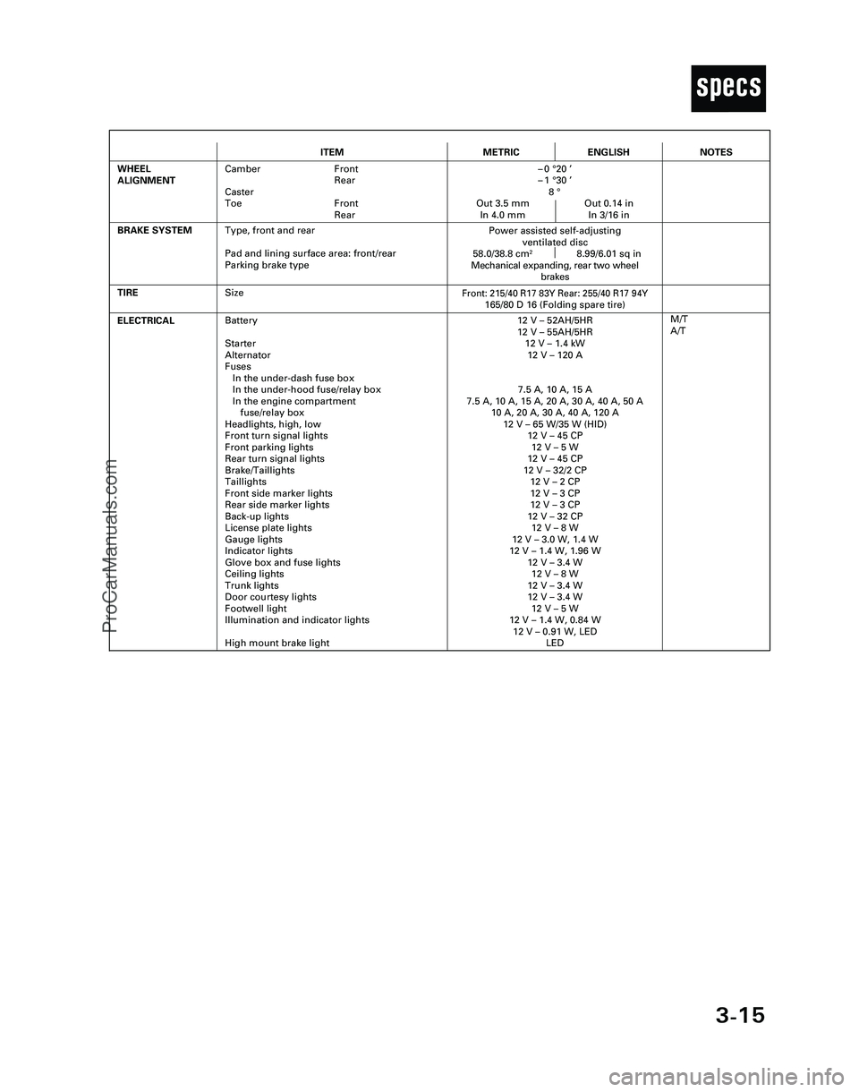
3-15
T
ITEMMETRICENGLISH
ELECTRICALBattery
Starter
Alternator
Fuses
In the under-dash fuse box
In the under-hood fuse/relay box
In the engine compartment
fuse/relay box
Headlights, high, low
Front turn signal lights
Front parking lights
Rear turn signal lights
Brake/Taillights
Taillights
Front side marker lights
Rear side marker lights
Back-up lights
License plate lights
Gauge lights
Indicator lights
Glove box and fuse lights
Ceiling lights
Trunk lights
Door courtesy lights
Footwell light
Illumination and indicator lights
High mount brake light12 V – 52AH/5HR
12 V – 55AH/5HR
12 V – 1.4 kW
12 V – 120 A
7.5 A, 10 A, 15 A
7.5 A, 10 A, 15 A, 20 A, 30 A, 40 A, 50 A
10 A, 20 A, 30 A, 40 A, 120 A
12 V – 65 W/35 W (HID)
12 V – 45 CP
12 V – 5 W
12 V – 45 CP
12 V – 32/2 CP
12 V – 2 CP
12 V – 3 CP
12 V – 3 CP
12 V – 32 CP
12 V – 8 W
12 V – 3.0 W, 1.4 W
12 V – 1.4 W, 1.96 W
12 V – 3.4 W
12 V – 8 W
12 V – 3.4 W
12 V – 3.4 W
12 V – 5 W
12 V – 1.4 W, 0.84 W
12 V – 0.91 W, LED
LED
TIRE
M/T
A/T
BRAKE SYSTEM
Front: 215/40 R17 83Y Rear: 255/40 R17 94Y165/80 D 16 (Folding spare tire)
Power assisted self-adjusting
ventilated disc
58.0/38.8 cm
28.99/6.01 sq in
Mechanical expanding, rear two wheel
brakes
WHEEL
ALIGNMENTCamber Front
Rear
Caster
Toe Front
Rear–0 °20 ’
–1 °30 ’
8 °
Out 3.5 mm Out 0.14 in
In 4.0 mm In 3/16 in
NOTES
Size
Type, front and rear
Pad and lining surface area: front/rear
Parking brake type
*04-NSX (61SW004)SEC03(01-16) 9/22/04 1:49 PM Page 3-15
ProCarManuals.com
Page 412 of 1503
21. Disconnect the engine wire harness connectors.
22. Remove the battery cable from the main fuse box.
24. Disconnect the two connectors from the emission
control box, then remove the control box.
• Do not disconnect the vacuum hoses.
Removal (cont'd)
Engine Removal/Installation
23. Disconnect the throttle body 6P connector, and
remove the ground cable and starter cable.
25. Remove the radiator hoses and heater hose.ProCarManuals.com
Page 560 of 1503
System Description
System Connectors [Front Compartment and Under-dash] (cont'd)
FLOOR
WIRE
HARNESS
UNDER-HOOD
FUSE/RELAY
BOX
FRONT
COMPARTMENT
WIRE
HARNESS
UNDER-DASH
FUSE
BOX
SIDE
WIRE
HARNESSProCarManuals.com
Page 562 of 1503
System Description
System Connectors [Front Compartment and Under-dash] (cont'd)
UNDER-HOOD
FUSE/RELAY
BOX
SUB RELAY
BOX A
FRONT
COMPARTMENT
WIRE
HARNESS
UNDER-DASH
FUSE
BOX
SIDE
WIRE
HARNESS
FLOOR
WIRE
HARNESSProCarManuals.com