Page 565 of 1503
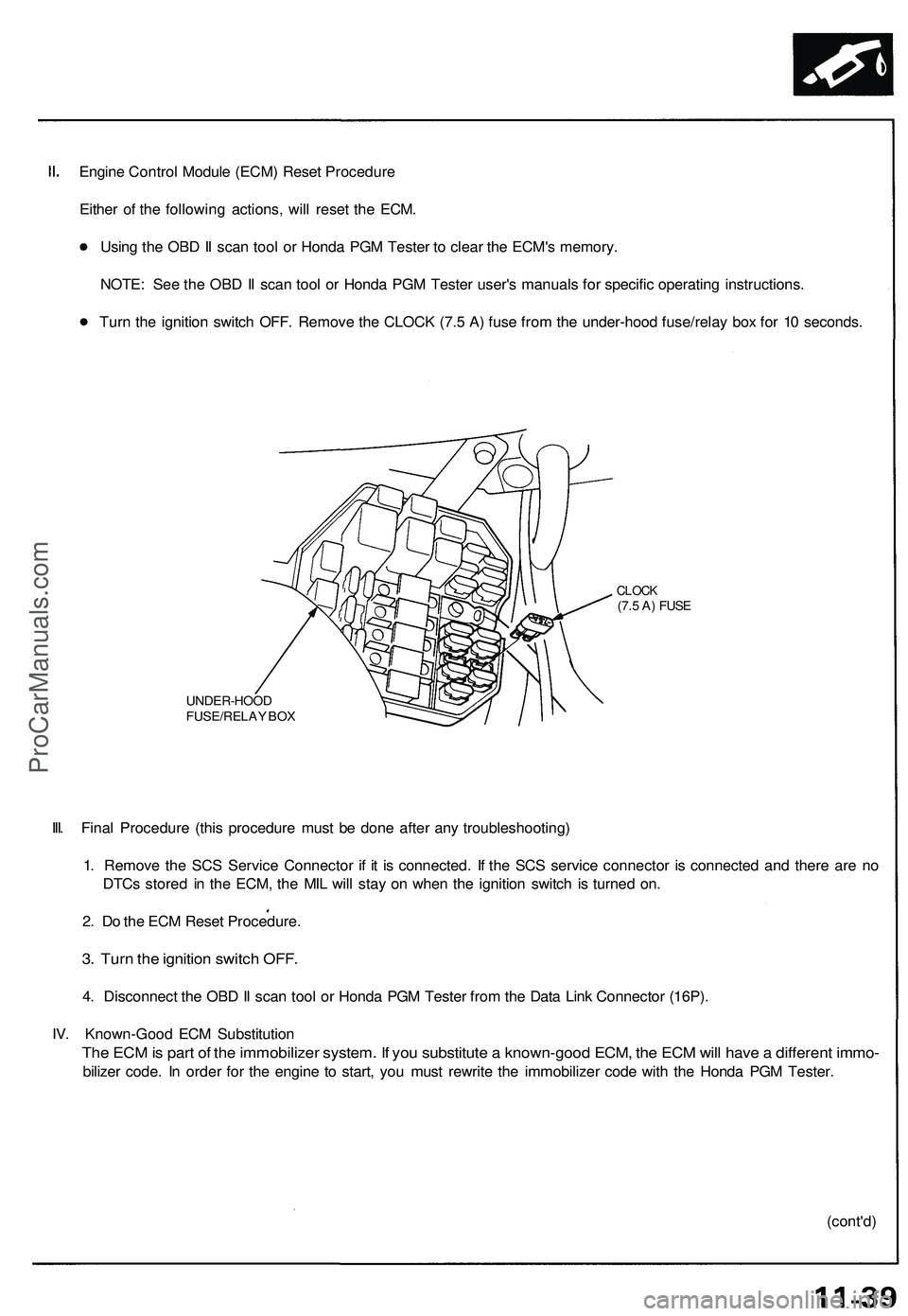
Engine Control Module (ECM) Reset Procedure
Either of the following actions, will reset the ECM.
Using the OBD II scan tool or Honda PGM Tester to clear the ECM's memory.
NOTE: See the OBD II scan tool or Honda PGM Tester user's manuals for specific operating instructions.
Turn the ignition switch OFF. Remove the CLOCK (7.5 A) fuse from the under-hood fuse/relay box for 10 seconds.
UNDER-HOOD
FUSE/RELAY BOX
CLOCK
(7.5 A) FUSE
III. Final Procedure (this procedure must be done after any troubleshooting)
1. Remove the SCS Service Connector if it is connected. If the SCS service connector is connected and there are no
DTCs stored in the ECM, the MIL will stay on when the ignition switch is turned on.
2. Do the ECM Reset Procedure.
3. Turn the ignition switch OFF.
4. Disconnect the OBD II scan tool or Honda PGM Tester from the Data Link Connector (16P).
IV. Known-Good ECM Substitution
The ECM is part of the immobilizer system. If you substitute a known-good ECM, the ECM will have a different immo-
bilizer code. In order for the engine to start, you must rewrite the immobilizer code with the Honda PGM Tester.
(cont'd)ProCarManuals.com
Page 587 of 1503
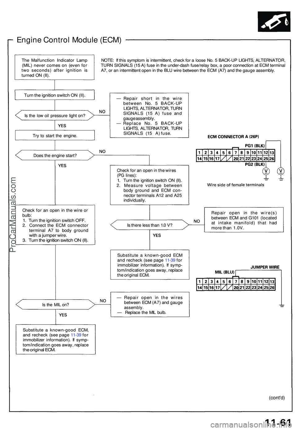
Engine Contro l Modul e (ECM )
NOTE: I f thi s sympto m is intermittent , chec k fo r a loos e No . 5 BACK-U P LIGHTS , ALTERNATOR ,
TUR N SIGNAL S (1 5 A ) fus e in th e under-das h fuse/rela y box , a poo r connectio n a t EC M termina l
A7 , o r a n intermitten t ope n in th e BL U wir e betwee n th e EC M (A7 ) an d th e gaug e assembly .
I s th e lo w oi l pressur e ligh t on ?
Tr y t o star t th e engine .
Doe s th e engin e start ?
Chec k fo r a n ope n in th e wir e o r
bulb :
1. Tur n th e ignitio n switc h OFF .2. Connec t th e EC M connecto r
termina l A 7 t o bod y groun d
with a jumpe r wire .3. Tur n th e ignitio n switc h O N (II) .
Is th e MI L on ?
Substitut e a known-goo d ECM ,
an d rechec k (se e pag e 11-3 9 fo r
immobilize r information) . I f symp -
tom/indicatio n goe s away , replac e
the origina l ECM .
— Repai r shor t i n the wir e
betwee n No . 5 BACK-U P
LIGHTS , ALTERNATOR , TUR N
SIGNAL S (1 5 A ) fus e an d
gaug e assembly .
— Replac e No . 5 BACK-U P
LIGHTS , ALTERNATOR , TUR N
SIGNALS (15 A) fuse.
Chec k fo r a n ope n in th e wire s
(PG lines) :1. Tur n th e ignitio n switc h O N (II) .
2 . Measur e voltag e betwee n
bod y groun d an d EC M con -
necto r terminal s A1 2 an d A2 5
individually .
I s ther e les s tha n 1. 0 V ?
Substitut e a known-goo d EC M
an d rechec k (se e pag e 11-3 9 fo r
immobilize r information) . I f symp -
tom/indicatio n goe s away , replac e
th e origina l ECM . Repai
r ope n i n th e wire(s )
betwee n EC M an d G10 1 (locate d
a t intak e manifold ) tha t ha d
mor e tha n 1.0V .
— Repai r ope n i n th e wire s
betwee n EC M (A7 ) an d gaug e
assembly .— Replac e th e MI L bulb .
(cont'd )
Turn th e ignitio n switc h O N (II) .
The Malfunctio n Indicato r Lam p
(MIL ) neve r come s o n (eve n fo r
tw o seconds ) afte r ignitio n i s
turne d O N (II) .
ProCarManuals.com
Page 589 of 1503
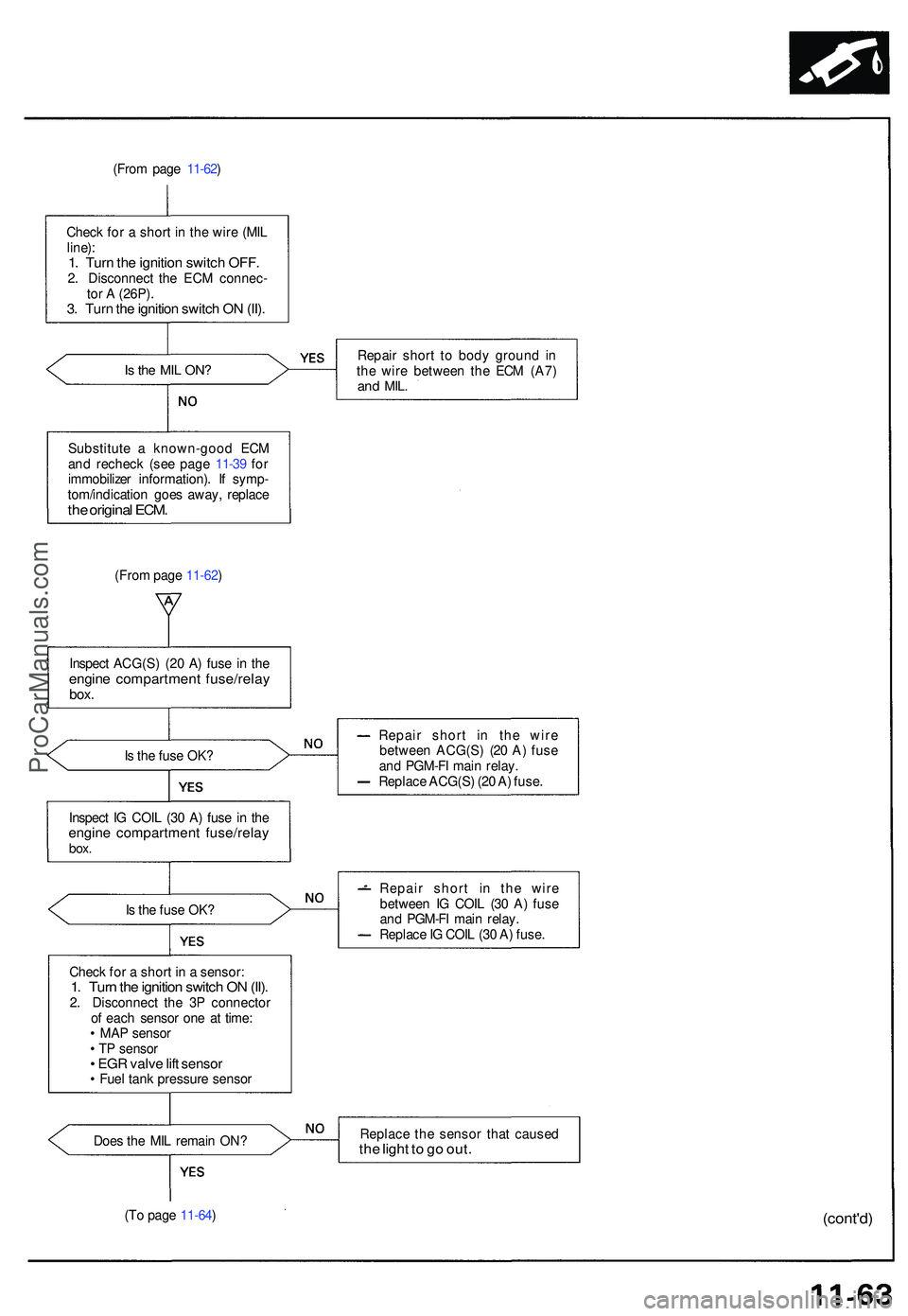
(From pag e 11-62 )
Chec k fo r a shor t i n th e wir e (MI L
line) :
1. Tur n th e ignitio n switc h OFF .2. Disconnec t th e EC M connec -
to r A (26P) .
3. Tur n th e ignitio n switc h O N (II) .
Is th e MI L ON ?Repai r shor t t o bod y groun d i n
th e wir e betwee n th e EC M (A7 )
and MIL .
Substitut e a known-goo d EC M
an d rechec k (se e pag e 11-3 9 fo r
immobilize r information) . I f symp -
tom/indicatio n goe s away , replac e
the origina l ECM .
(From pag e 11-62 )
Inspec t ACG(S ) (2 0 A ) fus e i n th e
engin e compartmen t fuse/rela ybox.
Is th e fus e OK ? Repai
r shor t i n th e wir e
betwee n ACG(S ) (2 0 A ) fus e
an d PGM-F I mai n relay .
Replac e ACG(S ) (2 0 A ) fuse .
Inspec t I G COI L (3 0 A ) fus e i n th e
engin e compartmen t fuse/rela ybox.
Is th e fus e OK ? Repai
r shor t i n th e wir e
betwee n I G COI L (3 0 A ) fus e
an d PGM-F I mai n relay .
Replac e IG COI L (3 0 A ) fuse .
Chec k fo r a shor t i n a sensor :
1. Tur n th e ignitio n switc h O N (II) .2. Disconnec t th e 3 P connecto r
o f eac h senso r on e a t time :
• MA P senso r
• T P senso r
• EG R valv e lif t senso r• Fue l tan k pressur e senso r
Doe s th e MI L remai n ON ? Replac
e th e senso r tha t cause d
the ligh t t o g o out .
(To pag e 11-64 )(cont'd )
ProCarManuals.com
Page 603 of 1503
Idle Control System
Starter Switch Signal
This signals the ECM when the engine is cranking.
NOTE:
• M/T: Clutch pedal must be depressed.
• A/T: Transmission in or position.
Is there battery voltage?
Is the fuse OK?
Repair short in the wire
between the ECM (C6) and
the No. 7 STARTER SIGNAL
(7.5 A) fuse or the PGM-FI
main relay.
Replace the No. 7 STARTER
SIGNAL (7.5 A) fuse.
Inspection of Starter Switch Sig-
nal.
Check for an open or short in the
wire (STS line):
Measure voltage between ECM
connector terminals C6 and A26
with the ignition switch in the
start (III) position.
Starter switch signal is OK.
Repair open in the wire between
the ECM
(C6)
and the No. 7
STARTER SIGNAL (7.5 A) fuse.
Inspect the No. 7 STARTER SIG-
NAL (7.5 A) fuse in the under-
dash fuse box.ProCarManuals.com
Page 618 of 1503
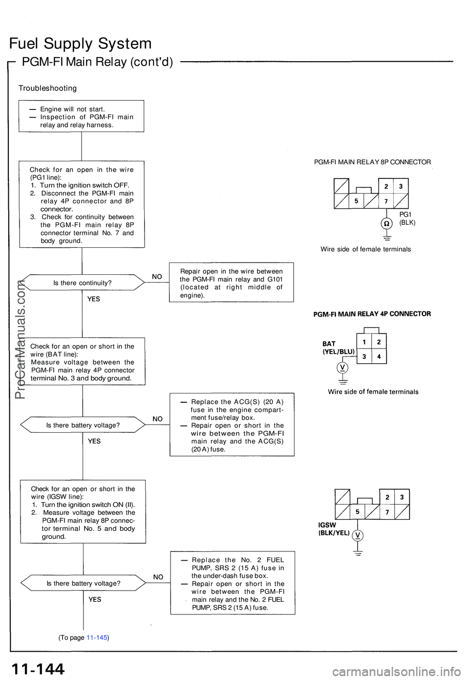
Fuel Suppl y Syste m
PGM-F I Mai n Rela y (cont'd )
Troubleshootin g
Engine wil l no t start .
Inspectio n o f PGM-F I mai n
rela y an d rela y harness .
Chec k fo r a n ope n i n th e wir e
(PG 1 line) :
1. Tur n th e ignitio n switc h OFF .2. Disconnec t th e PGM-F I mai n
rela y 4 P connecto r an d 8 P
connector .3. Chec k fo r continuit y betwee n
th e PGM-F I mai n rela y 8 P
connecto r termina l No . 7 an d
bod y ground .
I s ther e continuity ?
Chec k fo r a n ope n o r shor t i n th e
wir e (BA T line) :
Measur e voltag e betwee n th e
PGM-F I mai n rela y 4 P connecto r
terminal No . 3 an d bod y ground .
Is ther e batter y voltage ?
Chec k fo r a n ope n o r shor t i n th e
wir e (IGS W line) :
1. Tur n th e ignitio n switc h O N (II) .2. Measur e voltag e betwee n th e
PGM-F I mai n rela y 8 P connec -
tor termina l No . 5 an d bod yground .
PGM-FI MAI N RELA Y 8 P CONNECTO R
PG1(BLK )
Wire sid e o f femal e terminal s
Repai r ope n i n th e wir e betwee n
th e PGM-F I mai n rela y an d G10 1
(locate d a t righ t middl e o f
engine) .
Replac e th e ACG(S ) (2 0 A )
fus e i n th e engin e compart -
men t fuse/rela y box .
Repai r ope n o r shor t i n th e
wir e betwee n th e PGM-F Imain rela y an d th e ACG(S )
(2 0 A ) fuse .
I s ther e batter y voltage ?
(T o pag e 11-145 ) Replac
e th e No . 2 FUE L
PUMP , SR S 2 (1 5 A ) fus e i n
th e under-das h fus e box .
Repai r ope n o r shor t i n th e
wir e betwee n th e PGM-F I
mai n rela y an d th e No . 2 FUE L
PUMP , SR S 2 (1 5 A ) fuse .
ProCarManuals.com
Page 619 of 1503
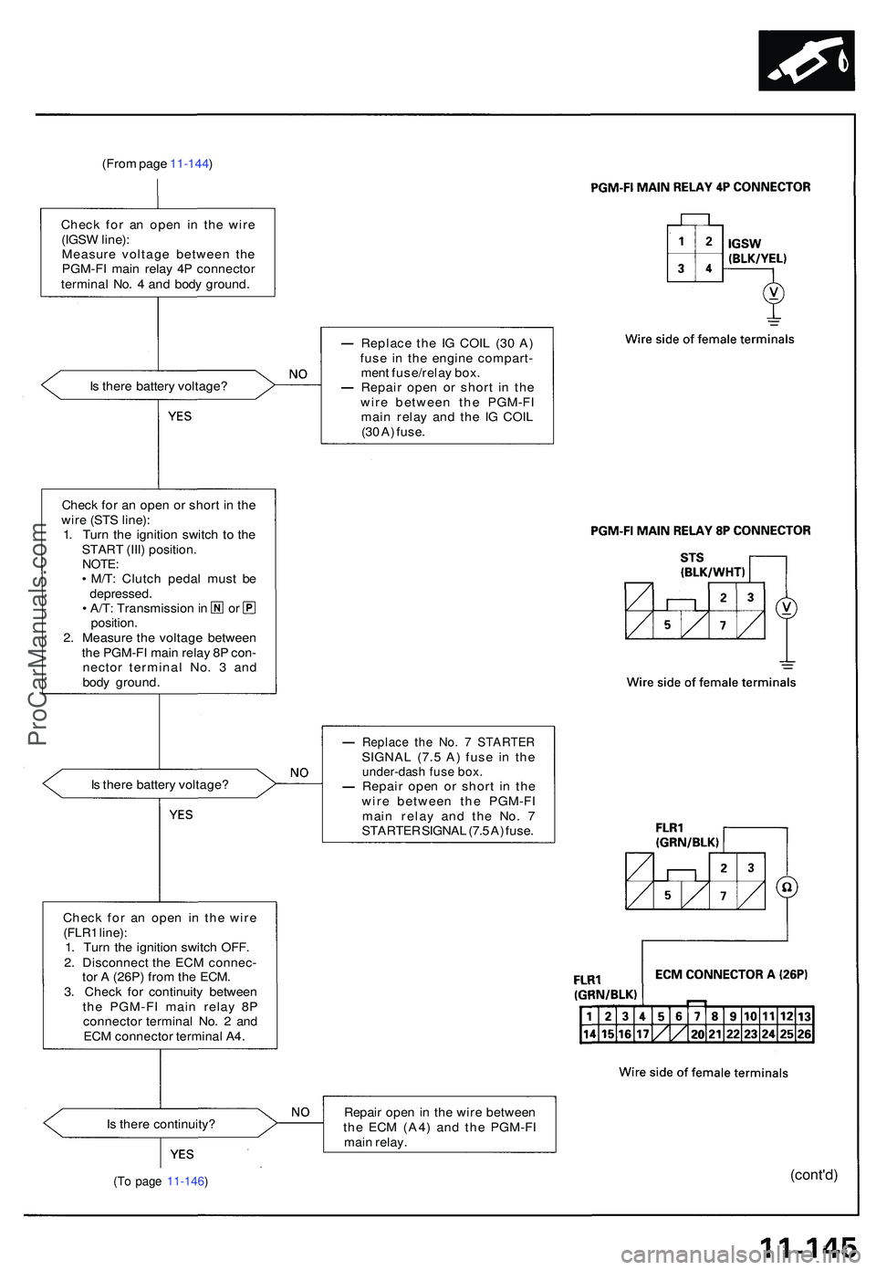
(From pag e 11-144 )
Chec k fo r a n ope n i n th e wir e
(IGS W line) :
Measur e voltag e betwee n th e
PGM-F I mai n rela y 4 P connecto r
termina l No . 4 an d bod y ground .
I s ther e batter y voltage ? Replac
e th e I G COI L (3 0 A )
fus e i n th e engin e compart -
men t fuse/rela y box .
Repai r ope n o r shor t i n th e
wir e betwee n th e PGM-F I
mai n rela y an d th e I G COI L
(3 0 A ) fuse .
Chec k fo r a n ope n o r shor t i n th e
wir e (ST S line) :
1 . Tur n th e ignitio n switc h t o th e
STAR T (III ) position .
NOTE:• M/T : Clutc h peda l mus t b e
depressed .
• A/T : Transmissio n in o r
position .
2 . Measur e th e voltag e betwee n
th e PGM-F I mai n rela y 8 P con -
necto r termina l No . 3 an d
bod y ground .
I s ther e batter y voltage ?
Replace th e No . 7 STARTE RSIGNAL (7. 5 A ) fus e i n th eunder-das h fus e box .Repai r ope n o r shor t i n th e
wir e betwee n th e PGM-F I
mai n rela y an d th e No . 7
STARTE R SIGNA L (7. 5 A ) fuse .
Chec k fo r a n ope n i n th e wir e
(FLR 1 line) :1. Tur n th e ignitio n switc h OFF .
2 . Disconnec t th e EC M connec -
to r A (26P ) fro m th e ECM .
3 . Chec k fo r continuit y betwee n
th e PGM-F I mai n rela y 8 P
connecto r termina l No . 2 an d
EC M connecto r termina l A4 .
I s ther e continuity ? Repai
r ope n in th e wir e betwee n
th e EC M (A4 ) an d th e PGM-F I
mai n relay .
(cont'd )(To pag e 11-146 )
ProCarManuals.com
Page 637 of 1503
EVAP Control Canister Removal/Installation
1. Remove the air cleaner housing.
2. Remove the engine compartment fuse/relay box
mounting bolts and harness clip.
AIR CLEANER
HOUSING
HARNESS CLIP
3. Remove the EVAP control canister bracket mount-
ing bolts.
4. Disconnect the hoses and connector from the EVAP
control canister.
5. Remove the dust filter from the dust filter bracket.
6. Remove the EVAP control canister and brackets.
EVAP CONTROL
CANISTER
DUST FILTER
BRACKET
EVAP CONTROL
CANISTER
BRACKET
DUST FILTER
7. Install the EVAP control canister in the reverse order
of removal.ProCarManuals.com
Page 638 of 1503
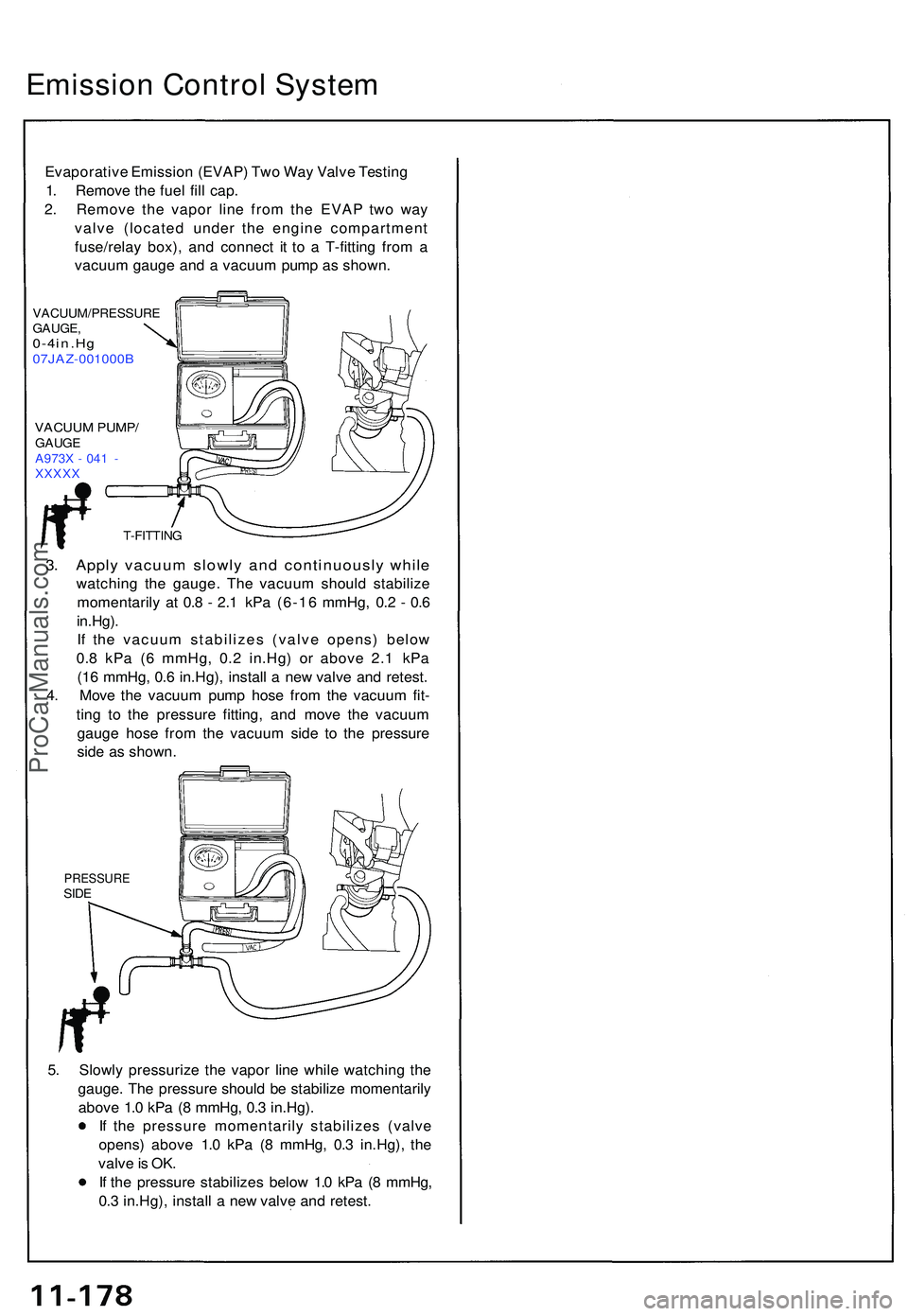
Emission Contro l Syste m
Evaporativ e Emissio n (EVAP ) Tw o Wa y Valv e Testin g
1 . Remov e th e fue l fil l cap .
2 . Remov e th e vapo r lin e fro m th e EVA P tw o wa y
valv e (locate d unde r th e engin e compartmen t
fuse/rela y box) , an d connec t i t t o a T-fittin g fro m a
vacuu m gaug e an d a vacuu m pum p a s shown .
VACUUM/PRESSUR E
GAUGE ,
0-4in.H g07JAZ-001000 B
VACUUM PUMP /GAUGE
A973 X - 04 1 -
XXXX X
3. Appl y vacuu m slowl y an d continuousl y whil e
watchin g th e gauge . Th e vacuu m shoul d stabiliz e
momentaril y a t 0. 8 - 2. 1 kP a (6-1 6 mmHg , 0. 2 - 0. 6
in.Hg) .
I f th e vacuu m stabilize s (valv e opens ) belo w
0. 8 kP a ( 6 mmHg , 0. 2 in.Hg ) o r abov e 2. 1 kP a
(1 6 mmHg , 0. 6 in.Hg) , instal l a ne w valv e an d retest .
4 . Mov e th e vacuu m pum p hos e fro m th e vacuu m fit -
tin g t o th e pressur e fitting , an d mov e th e vacuu m
gaug e hos e fro m th e vacuu m sid e t o th e pressur e
sid e a s shown .
PRESSUR ESIDE
5. Slowl y pressuriz e th e vapo r lin e whil e watchin g th e
gauge . Th e pressur e shoul d b e stabiliz e momentaril y
abov e 1. 0 kP a ( 8 mmHg , 0. 3 in.Hg) .
I f th e pressur e momentaril y stabilize s (valv e
opens ) abov e 1. 0 kP a ( 8 mmHg , 0. 3 in.Hg) , th e
valv e is OK .
I f th e pressur e stabilize s belo w 1. 0 kP a ( 8 mmHg ,
0. 3 in.Hg) , instal l a ne w valv e an d retest .
T-FITTIN G
ProCarManuals.com