Page 1392 of 1503
Horns
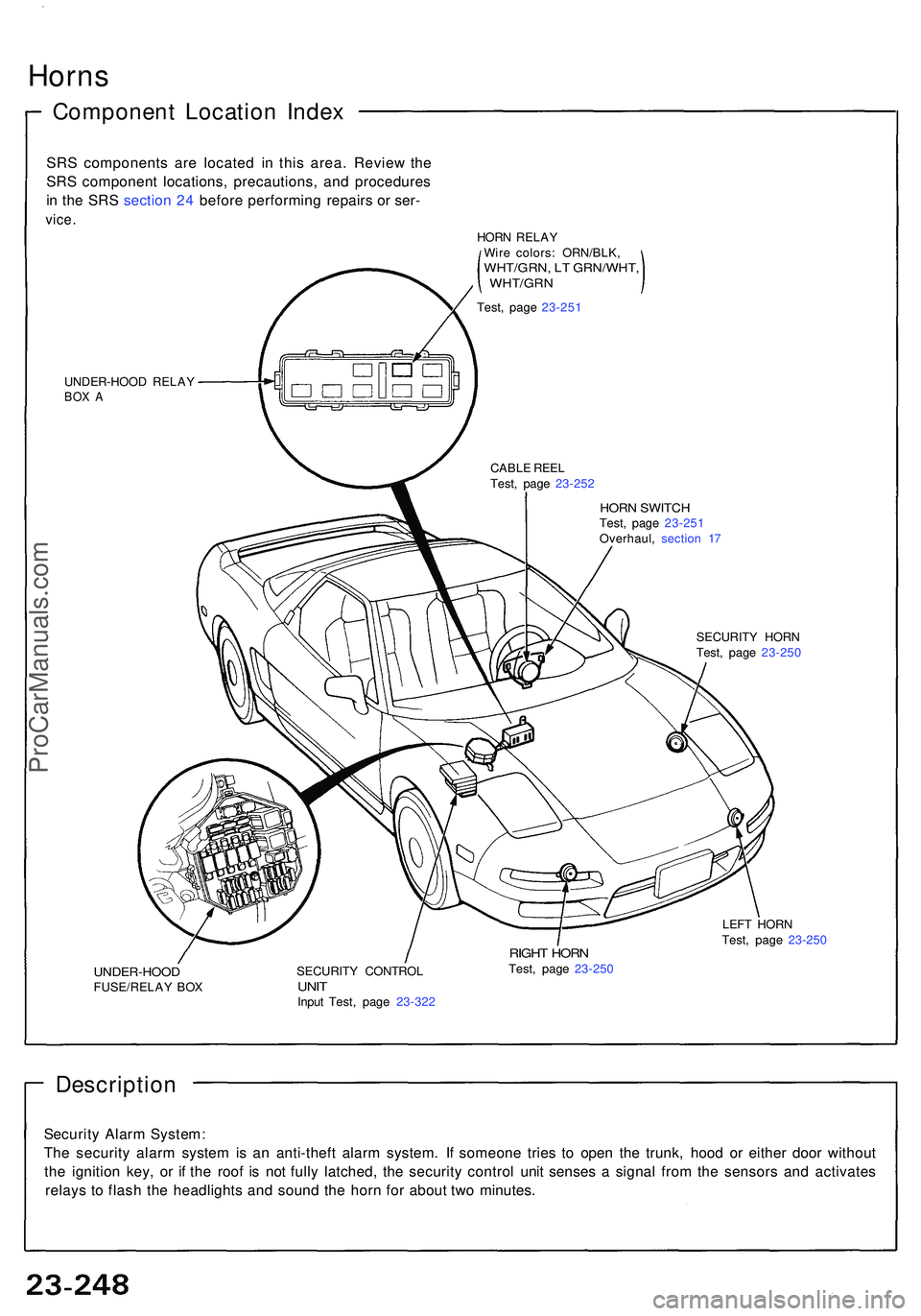
Componen t Locatio n Inde x
SRS component s ar e locate d i n thi s area . Revie w th e
SR S componen t locations , precautions , an d procedure s
i n th e SR S sectio n 24 befor e performin g repair s o r ser -
vice .
UNDER-HOO D RELA YBOX A
HOR N SWITC HTest, pag e 23-25 1
Overhaul , sectio n 1 7
CABL
E REE L
Test , pag e 23-25 2
SECURITY HOR N
Test , pag e 23-25 0
UNDER-HOO DFUSE/RELAY BO X SECURIT
Y CONTRO LUNITInpu t Test , pag e 23-32 2
RIGHT HOR NTest, pag e 23-25 0 LEF
T HOR N
Test , pag e 23-25 0
Descriptio n
Security Alar m System :
Th e securit y alar m syste m is a n anti-thef t alar m system . I f someon e trie s t o ope n th e trunk , hoo d o r eithe r doo r withou t
th e ignitio n key , o r i f th e roo f i s no t full y latched , th e securit y contro l uni t sense s a signa l fro m th e sensor s an d activate s
relay s t o flas h th e headlight s an d soun d th e hor n fo r abou t tw o minutes .
HORN RELA Y
Wir e colors : ORN/BLK ,
WHT/GRN, L T GRN/WHT ,, WHT/GR N
Test, pag e 23-25 1
ProCarManuals.com
Page 1402 of 1503
Function Test
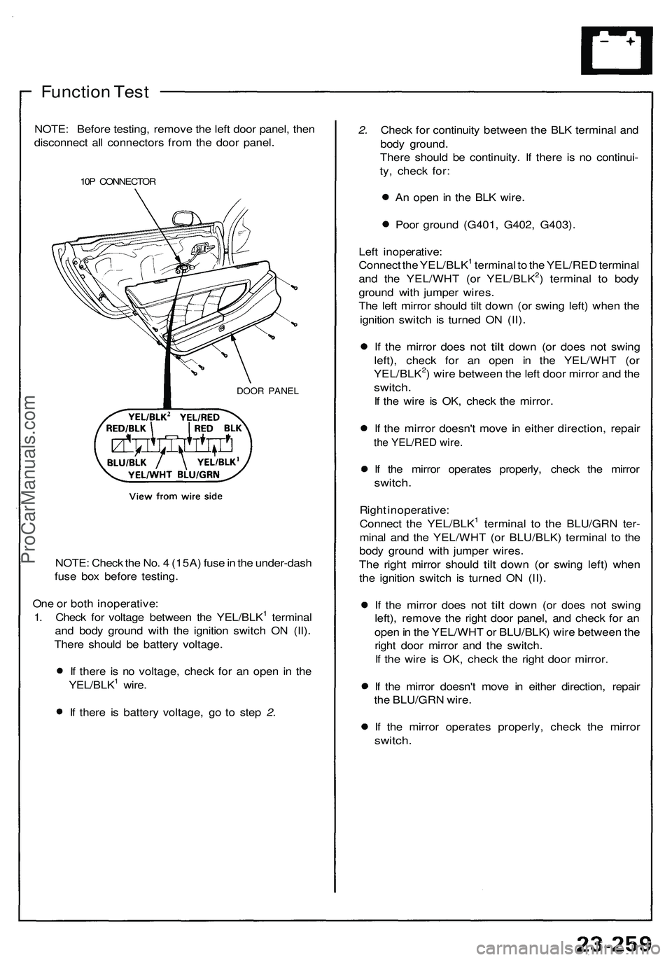
NOTE: Before testing, remove the left door panel, then
disconnect all connectors from the door panel.
10P CONNECTOR
DOOR PANEL
NOTE: Check the No. 4 (15A) fuse in the under-dash
fuse box before testing.
One or both inoperative:
1. Check for voltage between the YEL/BLK1 terminal
and body ground with the ignition switch ON (II).
There should be battery voltage.
If there is no voltage, check for an open in the
YEL/BLK1 wire.
If there is battery voltage, go to step 2.
2. Check for continuity between the BLK terminal and
body ground.
There should be continuity. If there is no continui-
ty, check for:
An open in the BLK wire.
Poor ground (G401, G402, G403).
Left inoperative:
Connect the YEL/BLK1 terminal to the YEL/RED terminal
and the YEL/WHT (or YEL/BLK2) terminal to body
ground with jumper wires.
The left mirror should tilt down (or swing left) when the
ignition switch is turned ON (II).
If the
mirror does
not
tilt
down
(or
does
not
swing
left), check for an open in the YEL/WHT (or
YEL/BLK2) wire between the left door mirror and the
switch.
If the wire is OK, check the mirror.
If the mirror doesn't move in either direction, repair
the YEL/RED wire.
If the mirror operates properly, check the mirror
switch.
Right inoperative:
Connect the YEL/BLK1 terminal to the BLU/GRN ter-
minal and the YEL/WHT (or BLU/BLK) terminal to the
body ground with jumper wires.
The
right
mirror should
tilt
down
(or
swing left) when
the ignition switch is turned ON (II).
If the
mirror does
not
tilt
down
(or
does
not
swing
left), remove the right door panel, and check for an
open in the YEL/WHT or BLU/BLK) wire between the
right door mirror and the switch.
If the wire is OK, check the right door mirror.
If the mirror doesn't move in either direction, repair
the BLU/GRN wire.
If the mirror operates properly, check the mirror
switch.ProCarManuals.com
Page 1413 of 1503
Power Window s
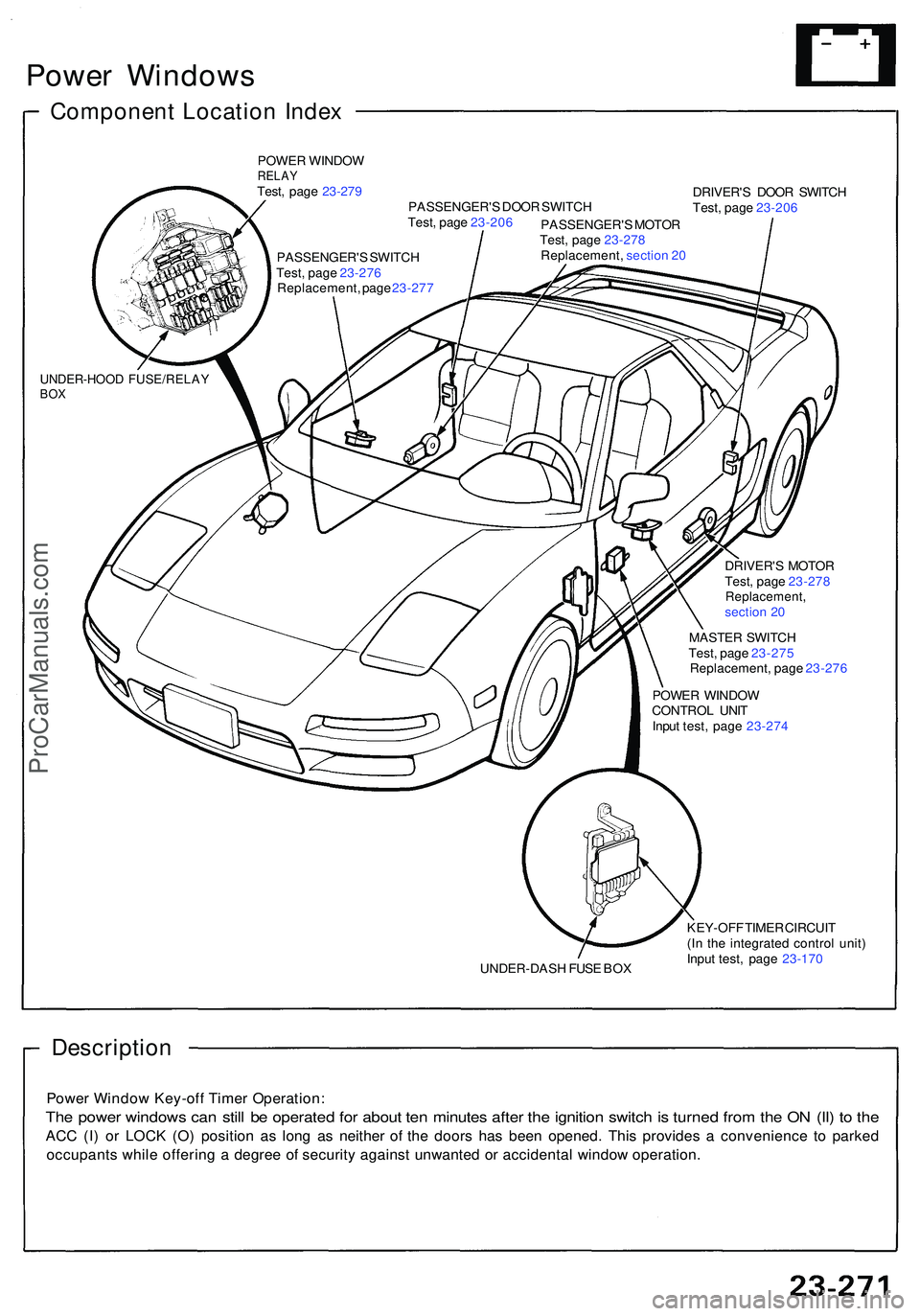
Componen t Locatio n Inde x
POWE R WINDO WRELAYTest, pag e 23-27 9
PASSENGER' S DOO R SWITC H DRIVER'
S DOO R SWITC H
Test , pag e 23-20 6
UNDER-HOO D FUSE/RELA YBOX
Test , pag e 23-20 6
PASSENGER' S MOTO R
Test , pag e 23-27 8
Replacement , sectio n 2 0
PASSENGER' S SWITC H
Test , pag e 23-27 6
Replacement , pag e 23-27 7
DRIVER'S MOTO R
Test , pag e 23-27 8
Replacement ,section 2 0
MASTE R SWITC H
Test , pag e 23-27 5
Replacement , pag e 23-27 6
POWE R WINDO W
CONTRO L UNI T
Inpu t test , pag e 23-27 4
UNDER-DAS H FUS E BO X KEY-OF
F TIME R CIRCUI T
(I n th e integrate d contro l unit )
Inpu t test , pag e 23-17 0
Descriptio n
Power Windo w Key-of f Time r Operation :
The powe r window s ca n stil l b e operate d fo r abou t te n minute s afte r th e ignitio n switc h is turne d fro m th e O N (II ) t o th e
AC C (I ) o r LOC K (O ) positio n a s lon g a s neithe r o f th e door s ha s bee n opened . Thi s provide s a convenienc e t o parke d
occupant s whil e offerin g a degre e o f securit y agains t unwante d o r accidenta l windo w operation .
ProCarManuals.com
Page 1420 of 1503
Relay Test
1. Remove the power window relay in the under-hood
fuse/relay box.
2. Check continuity at the relay terminals.
There should be continuity between the C and D
terminals.
There should be continuity between the A and B
terminals when power and ground are connect-
ed to the C and D terminals.
There should be no continuity between the A and
B terminals when power is disconnected.ProCarManuals.com
Page 1428 of 1503
Rear Windo w Defogge r
Relay Tes t
1. Remov e th e defogge r rela y i n th e engin e compart -
men t fuse/rela y box .
2 . Chec k continuit y a t th e rela y terminals .
• Ther e shoul d b e continuit y betwee n th e C an d D
terminals .
• Ther e shoul d b e continuit y betwee n th e A an d B
terminal s whe n powe r an d groun d ar e connecte d
t o th e C an d D terminals .
• Ther e shoul d b e n o continuit y betwee n th e A
an d B terminal s whe n powe r i s disconnected .
ProCarManuals.com
Page 1443 of 1503
Cruise Contro l
Troubleshootin g
NOTE:
Th e number s i n th e tabl e sho w th e troubleshootin g sequence .
Befor e troubleshooting :
— Chec k th e No . 5 (1 5 A ) fus e i n th e under-das h fus e box , an d th e No . 2 9 (5 0 A ) an d No . 4 5 (2 0 A ) fuse s i n th e under -
hoo d fuse/rela y box .
— Chec k tha t th e horn s sound .
— Mak e sur e tha t th e headlight s g o off .
ProCarManuals.com
Page 1452 of 1503
Security Alar m Syste m
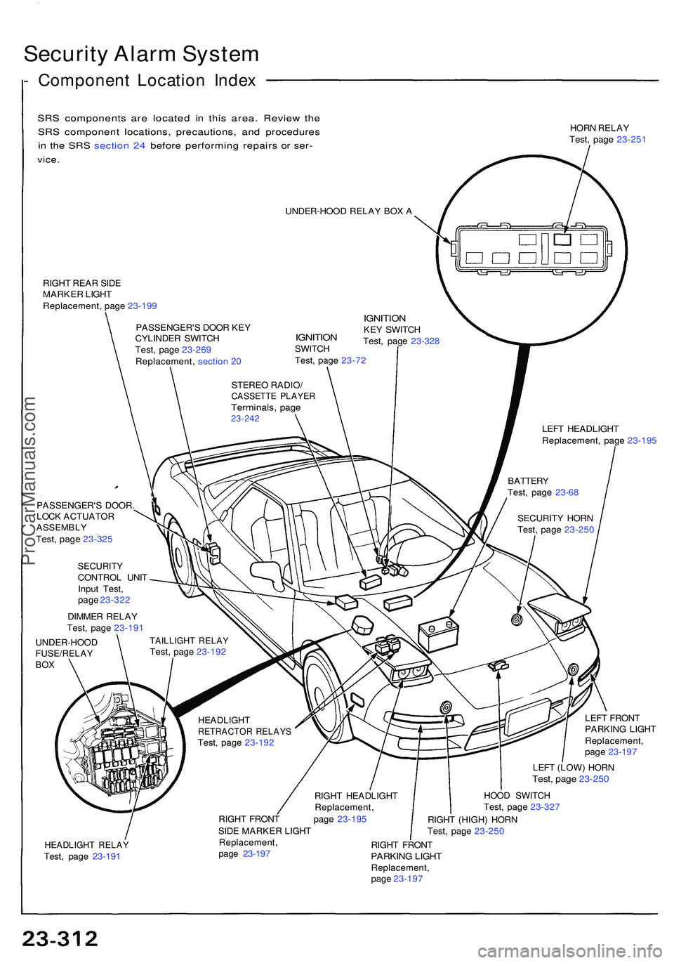
- Componen t Locatio n Inde x
SRS component s ar e locate d i n thi s area . Revie w th e
SR S componen t locations , precautions , an d procedure s
i n th e SR S sectio n 24 befor e performin g repair s o r ser -
vice .
HOR N RELA Y
Test , pag e 23-25 1
UNDER-HOO D RELA Y BO X A
RIGH T REA R SID E
MARKE R LIGH T
Replacement , pag e 23-19 9
PASSENGER' S DOO R KE Y
CYLINDE R SWITC H
Test , pag e 23-26 9
Replacement , sectio n 2 0
IGNITIO NSWITCH
Test , pag e 23-7 2
IGNITIO NKEY SWITC H
Test , pag e 23-32 8
STERE O RADIO /
CASSETT E PLAYE RTerminals , pag e23-24 2LEFT HEADLIGH T
Replacement , pag e 23-19 5
PASSENGER' S DOOR .
LOC K ACTUATO R
ASSEMBLYTest, pag e 23-32 5
SECURIT YCONTROL UNI T
Inpu t Test ,
pag e 23-32 2
DIMME R RELA Y
Test , pag e 23-19 1
UNDER-HOO D
FUSE/RELAYBOX
TAILLIGH T RELA YTest, pag e 23-19 2
HEADLIGH T
RETRACTO R RELAY STest, pag e 23-19 2
RIGHT HEADLIGH T
Replacement ,
RIGH T FRON T pag e 23-19 5
SID E MARKE R LIGH T LEF
T FRON T
PARKIN G LIGH T
Replacement ,
pag e 23-19 7
LEF T (LOW ) HOR N
Test, pag e 23-25 0
HOOD SWITC H
Test , pag e 23-32 7
RIGH T (HIGH ) HOR N
Test , pag e 23-25 0
HEADLIGH T RELA YTest, pag e 23-19 1 Replacement
,
pag e 23-19 7 RIGH
T FRON TPARKIN G LIGH TReplacement ,
pag e 23-19 7 SECURIT
Y HOR N
Test , pag e 23-25 0
BATTER
Y
Test , pag e 23-6 8
ProCarManuals.com
Page 1492 of 1503
Damaged Airbag or Tensioner Special Proce-
dure.
If an airbag or tensioner cannot be
deployed or triggered, it should not be treated as
normal scrap; it should still be considered a poten-
tially explosive device that can cause serious
injury.
1. If installed in a vehicle, follow the removal proce-
dures in this section.
2. Intertwine the stripped ends of the two airbag or ten-
sioner wires to make a short circuit.
3. Package the airbag or tensioner in exactly the same
packaging that the new replacement part came in.
4. Mark the outside of the box "DAMAGED AIRBAG
(or TENSIONER) NOT DEPLOYED" so it does not
get confused with your parts stock. If applicable,
also note on the box the VIN of the vehicle from
which it was removed.
5. Contact your Acura District Technical Manager for
how and where to return it for disposal.
Deployment Tool: Check Procedure.
1. Connect the yellow clips to both switch protector
handles on the tool; connect the tool to a battery.
2. Push the operation switch: green means the tool is
OK; red means the tool is faulty.
3. Disconnect the battery and the yellow clips.ProCarManuals.com