1997 ACURA NSX ignition
[x] Cancel search: ignitionPage 130 of 1503
II. Engine Control Module (ECM) Reset Procedure
Either of the following actions, will reset the ECM.
• Using the OBD II scan tool or Honda PGM Tester to clear the ECM's memory.
NOTE: See the OBD II scan tool or Honda PGM Tester user's manuals for specific operating instructions.
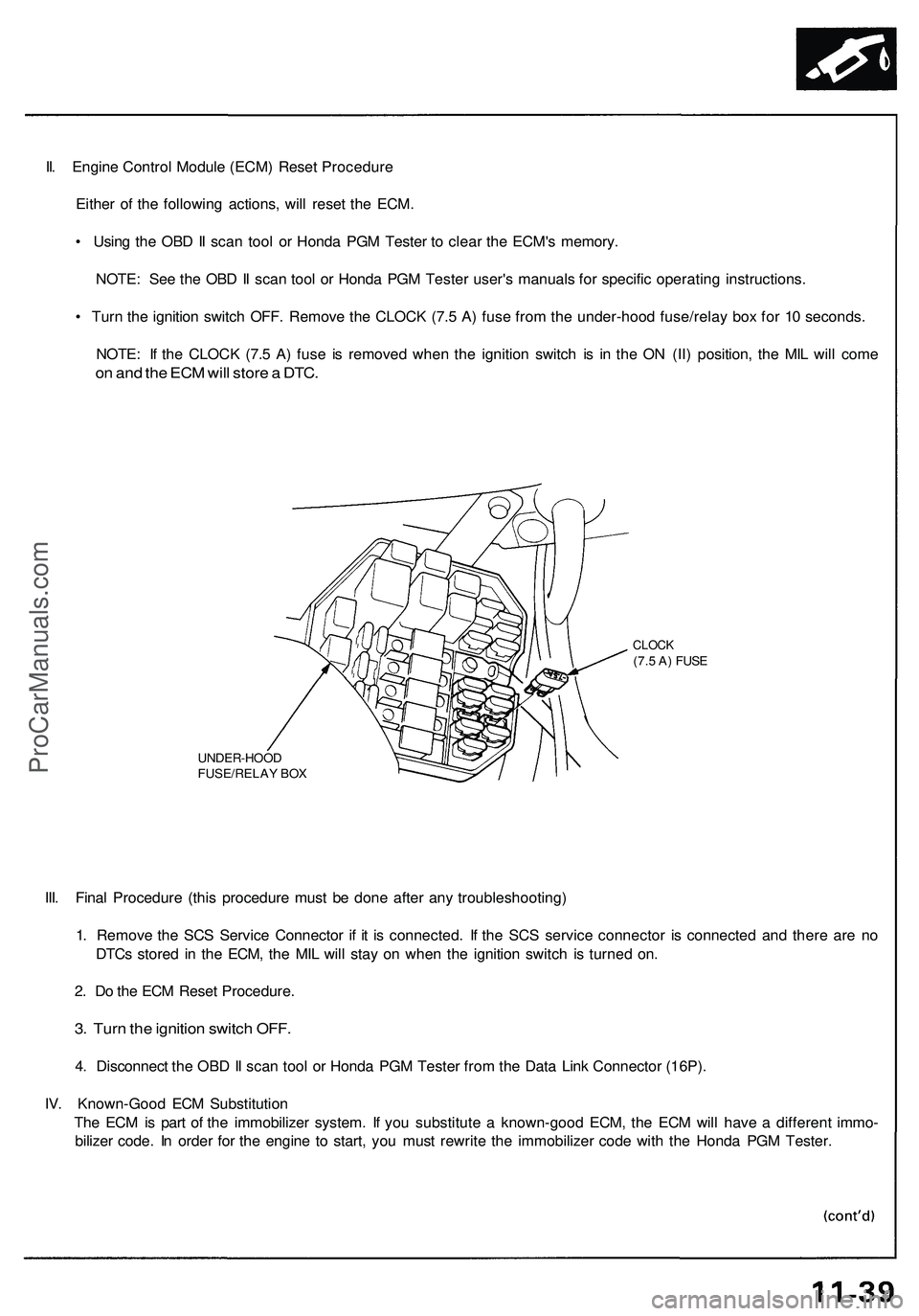
• Turn the ignition switch OFF. Remove the CLOCK (7.5 A) fuse from the under-hood fuse/relay box for 10 seconds.
NOTE: If the CLOCK (7.5 A) fuse is removed when the ignition switch is in the ON (II) position, the MIL will come
on and the ECM will store a DTC.
UNDER-HOOD
FUSE/RELAY BOX
CLOCK
(7.5 A) FUSE
III. Final Procedure (this procedure must be done after any troubleshooting)
1. Remove the SCS Service Connector if it is connected. If the SCS service connector is connected and there are no
DTCs stored in the ECM, the MIL will stay on when the ignition switch is turned on.
2. Do the ECM Reset Procedure.
3. Turn the ignition switch OFF.
4. Disconnect the OBD II scan tool or Honda PGM Tester from the Data Link Connector (16P).
IV. Known-Good ECM Substitution
The ECM is part of the immobilizer system. If you substitute a known-good ECM, the ECM will have a different immo-
bilizer code. In order for the engine to start, you must rewrite the immobilizer code with the Honda PGM Tester.ProCarManuals.com
Page 164 of 1503
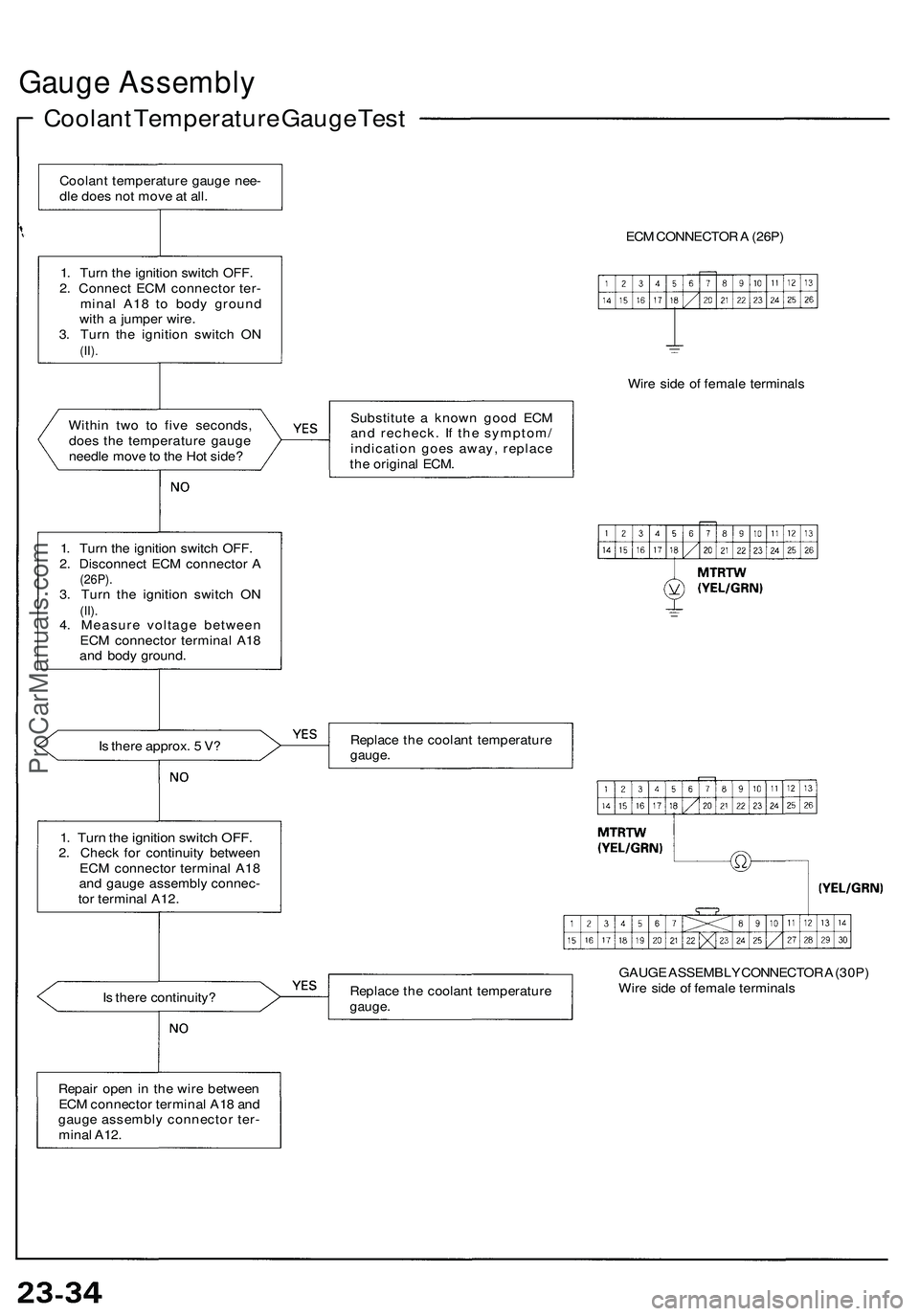
Gauge Assembly
Coolant Temperature Gauge Test
Within two to five seconds,
does the temperature gauge
needle move to the Hot side?
Is there approx. 5 V?
1. Turn the ignition switch OFF.
2. Check for continuity between
ECM connector terminal A18
and gauge assembly connec-
tor terminal A12.
Is there continuity?
ECM CONNECTOR A (26P)
Wire side of female terminals
Substitute a known good ECM
and recheck. If the symptom/
indication goes away, replace
the original ECM.
Replace the coolant temperature
gauge.
Replace the coolant temperature
gauge.
GAUGE ASSEMBLY CONNECTOR A (30P)
Wire side of female terminals
Coolant temperature gauge nee-
dle does not move at all.
1. Turn the ignition switch OFF.
2. Connect ECM connector ter-
minal A18 to body ground
with a jumper wire.
3. Turn the ignition switch ON
(II).
1. Turn the ignition switch OFF.
2. Disconnect ECM connector A
(26P).
3. Turn the ignition switch ON
(II).
4. Measure voltage between
ECM connector terminal A18
and body ground.
Repair open in the wire between
ECM connector terminal A18 and
gauge assembly connector ter-
minal A12.ProCarManuals.com
Page 165 of 1503
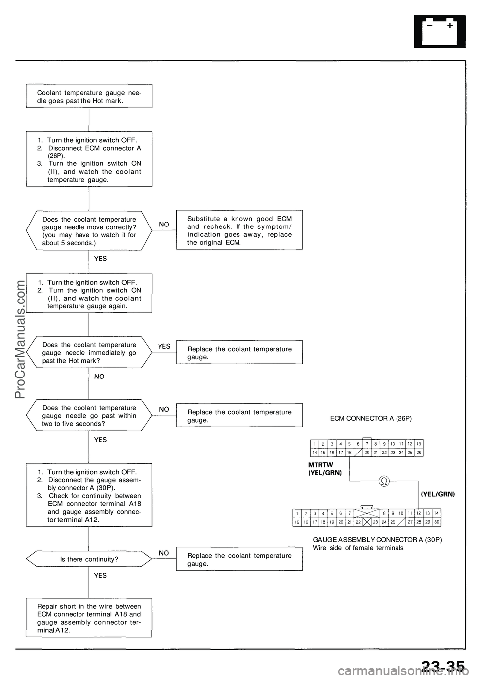
Does the coolant temperature
gauge needle move correctly?
(you may have to watch it for
about 5 seconds.)
1. Turn the ignition switch OFF.
2. Turn the ignition switch ON
(II), and watch the coolant
temperature gauge again.
Does the coolant temperature
gauge needle immediately go
past the Hot mark?
Does the coolant temperature
gauge needle go past within
two to five seconds?
1. Turn the ignition switch OFF.
2. Disconnect the gauge assem-
bly connector A (30P).
3. Check for continuity between
ECM connector terminal A18
and gauge assembly connec-
tor terminal A12.
Is there continuity?
Substitute a known good ECM
and recheck. If the symptom/
indication goes away, replace
the original ECM.
Replace the coolant temperature
gauge.
Replace the coolant temperature
gauge.
ECM CONNECTOR A (26P)
Replace the coolant temperature
gauge.
GAUGE ASSEMBLY CONNECTOR A (30P)
Wire side of female terminals
Repair short in the wire between
ECM connector terminal A18 and
gauge assembly connector ter-
minal A12.
1. Turn the ignition switch OFF.
2. Disconnect ECM connector A
(26P).
3. Turn the ignition switch ON
(II), and watch the coolant
temperature gauge.
Coolant temperature gauge nee-
dle goes past the Hot mark.ProCarManuals.com
Page 193 of 1503
Radiator
Engine Coolant Refilling and Bleeding
CAUTION: When pouring engine coolant, be sure to
shut the relay box lid and not let coolant spill on the
electrical parts or the paint. If any coolant spills, rinse it
off immediately.
NOTE:
• Perform this maintenance when the engine is cool.
• Before replacing the coolant, turn the ignition ON,
slowly turn the climate control temperature knob to
90° and turn off the ignition. This will allow the
coolant in the heater to drain out with the rest of the
system.
1. Open the hood, the rear window and the engine
cover.
2. Remove the cover protecting the water pipes and
shift cables on the underside of the car.
3. Before removing the expansion tank cap, first
loosen the cap to lower pressure.
CAUTION: Do not remove the expansion tank cap
when engine is hot. The coolant is under pressure
and may blow out and scald you. Open the cap
slowly when the engine is cool.
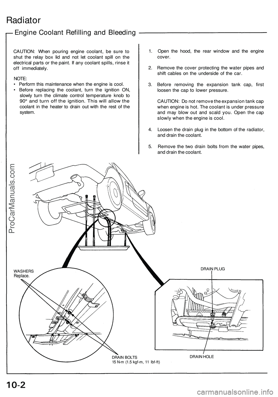
4. Loosen the drain plug in the bottom of the radiator,
and drain the coolant.
5. Remove the two drain bolts from the water pipes,
and drain the coolant.
DRAIN BOLTS
15 N-m (1.5 kgf-m, 11 Ibf-ft)
DRAIN HOLE
DRAIN PLUG
WASHERS
Replace.ProCarManuals.com
Page 349 of 1503
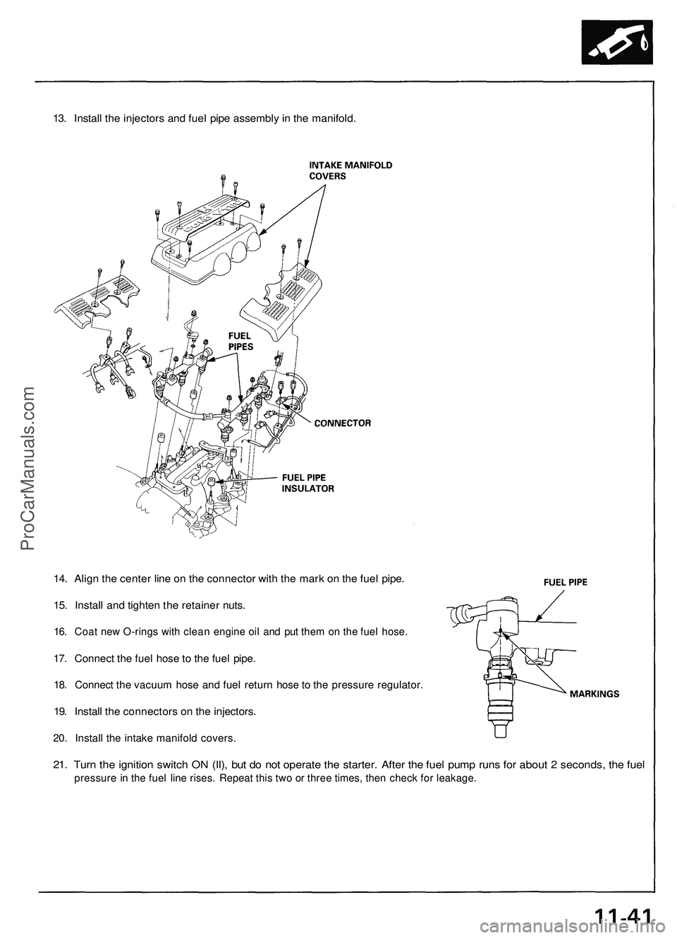
13. Install the injectors and fuel pipe assembly in the manifold.
14. Align the center line on the connector with the mark on the fuel pipe.
15. Install and tighten the retainer nuts.
16. Coat new O-rings with clean engine oil and put them on the fuel hose.
17. Connect the fuel hose to the fuel pipe.
18. Connect the vacuum hose and fuel return hose to the pressure regulator.
19. Install the connectors on the injectors.
20. Install the intake manifold covers.
21. Turn the ignition switch ON (II), but do not operate the starter. After the fuel pump runs for about 2 seconds, the fuel
pressure in the fuel line rises. Repeat this two or three times, then check for leakage.ProCarManuals.com
Page 359 of 1503
Transmitter Test
NOTE:
• If the doors unlock or lock with the transmitter, but
the LED on the transmitter does not come on, the
LED is faulty; replace the transmitter.
• If any door is open, you cannot lock the door with the
transmitter.
• If you unlocked the doors with the transmitter, but do
not open any of the doors within 30 seconds, the
doors relock automatically.
• The doors do not lock or unlock with the transmitter
if the ignition key is inserted in the ignition switch.
1. Press the lock or unlock button five or six times to
reset the transmitter.
• If the locks work, the transmitter is OK.
• If the locks don't work, go to step 2.
2. Open the transmitter and recheck for water damage.
• If you find any water damage, replace the transmit-
ter.
• If there is no water damage, go to step 3.
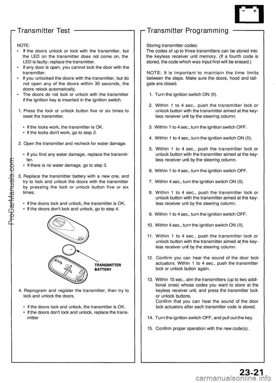
3. Replace the transmitter battery with a new one, and
try to lock and unlock the doors with the transmitter
by pressing the lock or unlock button five or six
times.
• If the doors lock and unlock, the transmitter is OK.
• If the doors don't lock and unlock, go to step 4.
4. Reprogram and register the transmitter, then try to
lock and unlock the doors.
• If the doors lock and unlock, the transmitter is OK.
• If the doors don't lock and unlock, replace the trans-
mitter
Transmitter Programming
Storing transmitter codes:
The codes of up to three transmitters can be stored into
the keyless receiver unit memory. (If a fourth code is
stored, the code which was input first will be erased.)
NOTE: It is important to maintain the time limits
between the steps. Make sure the doors, hood and tail-
gate are closed.
1. Turn the ignition switch ON (II).
2. Within 1 to 4 sec., push the transmitter lock or
unlock button with the transmitter aimed at the key-
less receiver unit by the steering column.
3. Within 1 to 4 sec., turn the ignition switch OFF.
4. Within 1 to 4 sec., turn the ignition switch ON (II).
5. Within 1 to 4 sec., push the transmitter lock or
unlock button with the transmitter aimed at the key-
less receiver unit by the steering column.
6. Within 1 to 4 sec., turn the ignition switch OFF.
7. Within 4 sec., turn the ignition switch ON (II).
8. Within 1 to 4 sec., push the transmitter lock or
unlock button with the transmitter aimed at the key-
less receiver unit by the steering column.
9. Within 1 to 4 sec., turn the ignition switch OFF.
10. Within 4 sec., turn the ignition switch ON (II).
11. Within 1 to 4 sec., push the transmitter lock or
unlock button with the transmitter aimed at the key-
less receiver unit by the steering column.
12. Confirm you can hear the sound of the door lock
actuators. Within 1 to 4 sec., push the transmitter
lock or unlock button again.
13. Within 10 sec., aim the transmitters (up to two addi-
tional ones) whose codes you want to store at the
keyless receiver unit, and press the transmitter lock
or unlock buttons.
Confirm that you can hear the sound of the door
lock actuators after each transmitter code is stored.
14. Turn the ignition switch OFF, and pull out the key.
15. Confirm proper operation with the new code(s).ProCarManuals.com
Page 432 of 1503
Removal
NOTE:
• Befor e removin g th e belt , tur n th e crankshaf t pulle y
s o th e No . 1 pisto n i s a t to p dea d cente r (TDC ) (se e
pag e 6-19 ).
• Inspec t th e wate r pum p afte r removin g th e timin g
bel t (se e pag e 10-11 ).
• I f i t i s t o b e reused , mar k th e directio n o f rotatio n o n
th e belt .
• Replac e th e timin g bel t a t 105,00 0 mile s (168,00 0 km )
accordin g t o th e maintenanc e schedul e (norma l con -
ditions/sever e conditions) . I f th e vehicl e i s regularl y
driven i n on e o r mor e o f th e followin g conditions ,
replace th e timin g bel t a t 60,00 0 mile s (U.S.A. )
100,00 0 k m (Canada) .
— In ver y hig h temperature s (ove r 110°F , 43°C) .
— In ver y lo w temperature s (unde r -20°F , -29°C) .
1 . Disconnec t th e batter y negativ e termina l first , the n
th e positiv e terminal .
2 . Remov e th e righ t rea r wheel/tire .
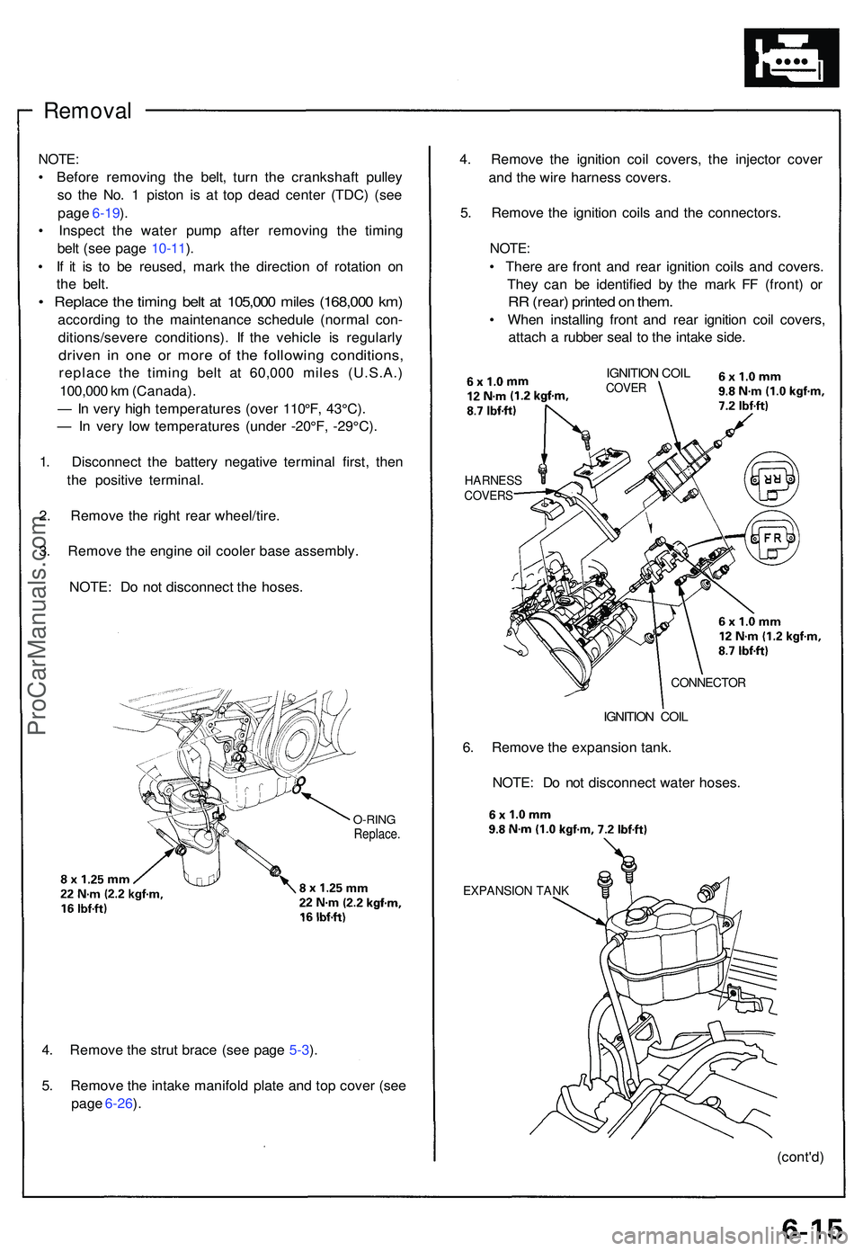
3 . Remov e th e engin e oi l coole r bas e assembly .
NOTE : D o no t disconnec t th e hoses .
O-RINGReplace .
4. Remov e th e stru t brac e (se e pag e 5-3 ).
5 . Remov e th e intak e manifol d plat e an d to p cove r (se e
pag e 6-26 ). 4
. Remov e th e ignitio n coi l covers , th e injecto r cove r
an d th e wir e harnes s covers .
5 . Remov e th e ignitio n coil s an d th e connectors .
NOTE:
• Ther e ar e fron t an d rea r ignitio n coil s an d covers .
The y ca n b e identifie d b y th e mar k F F (front ) o r
RR (rear ) printe d o n them .
• Whe n installin g fron t an d rea r ignitio n coi l covers ,
attac h a rubbe r sea l t o th e intak e side .
HARNES SCOVERS
IGNITION COI LCOVE R
CONNECTO R
IGNITION COI L
6. Remov e th e expansio n tank .
NOTE : D o no t disconnec t wate r hoses .
EXPANSIO N TAN K
(cont'd )
ProCarManuals.com
Page 444 of 1503
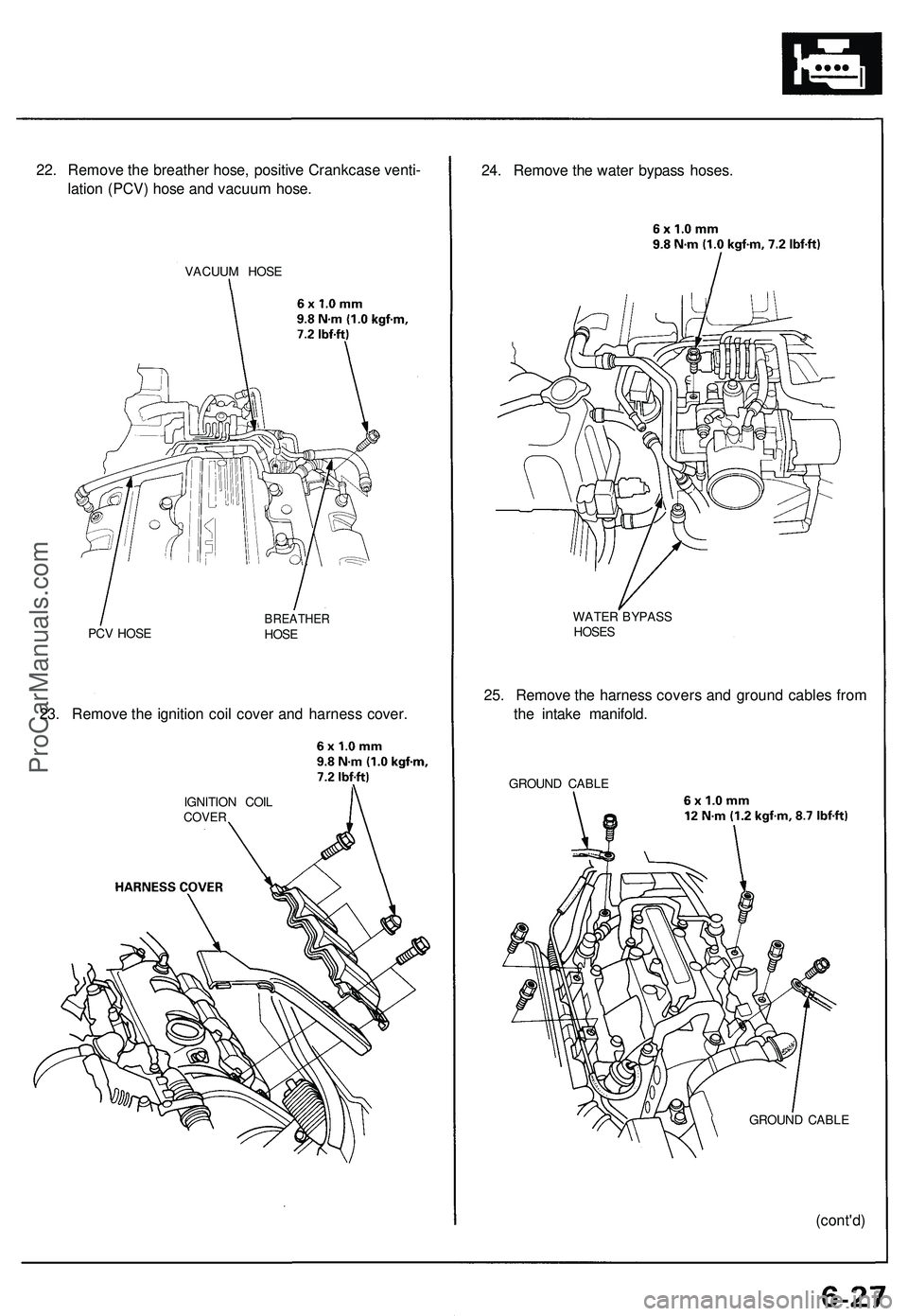
22. Remove the breather hose, positive Crankcase venti-
lation (PCV) hose and vacuum hose.
VACUUM HOSE
PCV HOSE
BREATHER
HOSE
23. Remove the ignition coil cover and harness cover.
IGNITION COIL
COVER
24. Remove the water bypass hoses.
WATER BYPASS
HOSES
25. Remove the harness covers and ground cables from
the intake manifold.
GROUND CABLE
GROUND CABLE
(cont'd)ProCarManuals.com