Page 1187 of 1503
Function Selection and Operation Check
This check will quickly and automatically select and operate all functions of the climate control system, in the combina-
tions and sequence shown below. It may help clarify a problem, or identify one that didn't show up when you perform
the self-diagnosis circuit check.
Turn the FAN switch to AUTO, then push in both the MODE and AUTO buttons and hold them in while you start the
engine. The control unit will then automatically run the check in eight steps, one step every five seconds.
To stop at one of those steps, push the MODE button; to continue, push it again for each step after that.
Pushing the OFF button or turning the ignition OFF, will turn off the check.
Check the temperature, volume, and source of the air flow, and compare it to what the chart shows it should be.ProCarManuals.com
Page 1195 of 1503
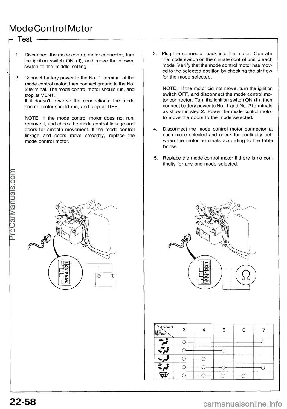
Mode Control Motor
Test
1. Disconnect the mode control motor connector, turn
the ignition switch ON (II), and move the blower
switch to the middle setting.
2. Connect battery power to the No. 1 terminal of the
mode control motor, then connect ground to the No.
2 terminal. The mode control motor should run, and
stop at VENT.
If it doesn't, reverse the connections; the mode
control motor should run, and stop at DEF.
NOTE: If the mode control motor does not run,
remove it, and check the mode control linkage and
doors for smooth movement. If the mode control
linkage and doors move smoothly, replace the
mode control motor.
3. Plug the connector back into the motor. Operate
the mode switch on the climate control unit to each
mode. Verify that the mode control motor has mov-
ed to the selected position by checking the air flow
for the mode selected.
NOTE: If the motor did not move, turn the ignition
switch OFF, and disconnect the mode control mo-
tor connector. Turn the ignition switch ON (II), then
connect battery power to No. 1 and No. 2 terminals
as shown in step 2. Power the mode control motor
to move the doors to the mode selected.
4. Disconnect the mode control motor connector at
each mode selected and check for continuity bet-
ween the motor terminals according to the table
below.
5. Replace the mode control motor if there is no con-
tinuity for any one mode selected.ProCarManuals.com
Page 1245 of 1503
Ignition Switch
Test
1. Remove the dashboard lower cover (see next
column).
2. Disconnect the 7P connector from the floor wire
harness.
3. Check for continuity between the terminals in each
switch position according to the table.
7P CONNECTOR
BLK/YEL (IG1)
BLU/WHT (IG2-B)
View from
wire side
BLK/WHT 1ST)
WHT/BLK (BAT-B)
WHT/RED (ACC)
Electrical Switch Replacement
1. Remove the dashboard lower cover, and disconnect
the floor wire harness connectors.
DASHBOARD
LOWER
COVER
2. Disconnect the 7P connector from the floor wire
harness.
3. Insert the key, and turn it to "0".
4. Remove the two screws, and replace the switch.
LOCK CYLINDER
SWITCH
WHT (IG2-A)
WHT (BAT-A)ProCarManuals.com
Page 1247 of 1503
Ignition Switch
Steering Lock Removal/Installation (cont'd)
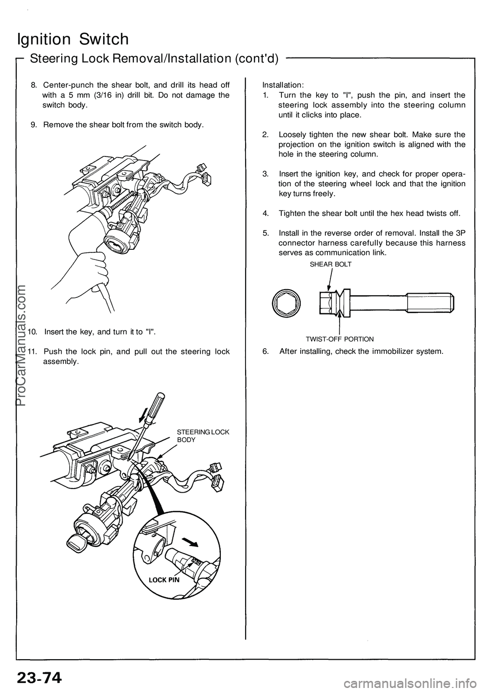
8. Center-punch the shear bolt, and drill its head off
with a 5 mm (3/16 in) drill bit. Do not damage the
switch body.
9. Remove the shear bolt from the switch body.
10. Insert the key, and turn it to "I".
11. Push the lock pin, and pull out the steering lock
assembly.
STEERING LOCK
BODY
Installation:
1. Turn the key to "I", push the pin, and insert the
steering lock assembly into the steering column
until it clicks into place.
2. Loosely tighten the new shear bolt. Make sure the
projection on the ignition switch is aligned with the
hole in the steering column.
3. Insert the ignition key, and check for proper opera-
tion of the steering wheel lock and that the ignition
key turns freely.
4. Tighten the shear bolt until the hex head twists off.
5. Install in the reverse order of removal. Install the 3P
connector harness carefully because this harness
serves as communication link.
SHEAR BOLT
TWIST-OFF PORTION
6. After installing, check the immobilizer system.ProCarManuals.com
Page 1251 of 1503
— If the starter still does not crank the engine,
remove the starter and diagnose its internal
problems.
— If the starter cranks the engine, check for an
open in the BLK/WHT wire and connectors be-
tween the starter and ignition switch. Check the
ignition switch.
On cars with automatic transmission, check the
A/T gear position switch (neutral position
switch) and connector.
On cars with manual transmission, check the
starter cut relay, clutch interlock switch and
connectors.
NOTE: Check the No. 29 (50 A) fuse and the
starter cut relay, and inspect the security alarm
system.
3. Check for wear or damage:
The starter should crank the engine smoothly and
steadily.
If the starter engages, but cranks the engine er-
ratically, remove the starter motor. Inspect the
starter, drive gear and flywheel ring gear for
damage.
Check the drive gear overrunning clutch for binding
or slipping when the armature is rotated with the
drive gear held. Replace the gears if damaged.
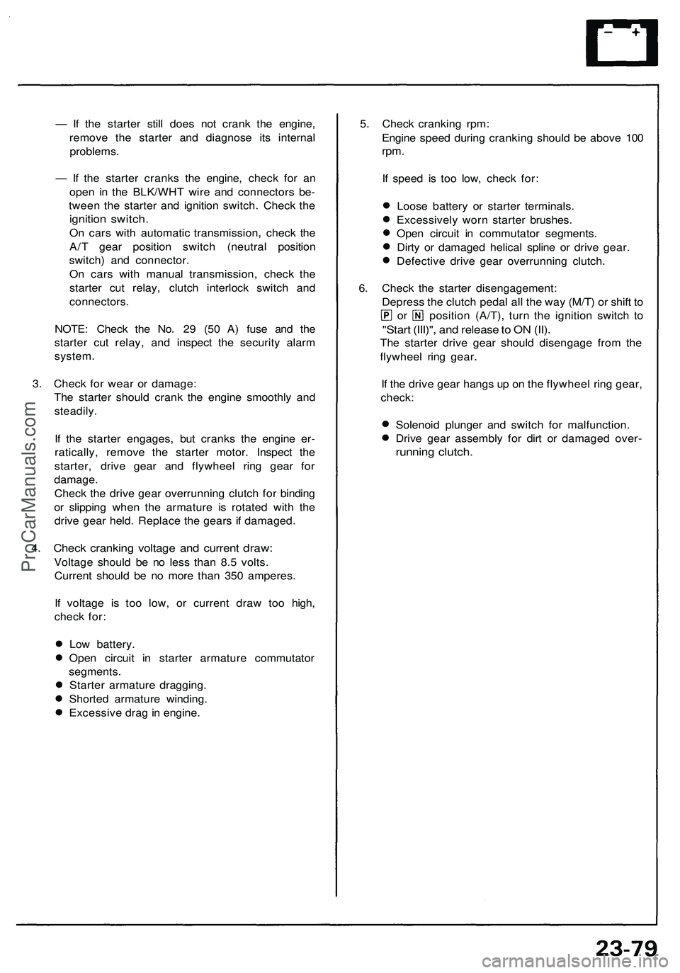
4. Check cranking voltage and current draw:
Voltage should be no less than 8.5 volts.
Current should be no more than 350 amperes.
If voltage is too low, or current draw too high,
check for:
Low battery.
Open circuit in starter armature commutator
segments.
Starter armature dragging.
Shorted armature winding.
Excessive drag in engine.
5. Check cranking rpm:
Engine speed during cranking should be above 100
rpm.
If speed is too low, check for:
Loose battery or starter terminals.
Excessively worn starter brushes.
Open circuit in commutator segments.
Dirty or damaged helical spline or drive gear.
Defective drive gear overrunning clutch.
6. Check the starter disengagement:
Depress the clutch pedal all the way (M/T) or shift to
or position (A/T), turn the ignition switch to
"Start (III)", and release to ON (II).
The starter drive gear should disengage from the
flywheel ring gear.
If the drive gear hangs up on the flywheel ring gear,
check:
Solenoid plunger and switch for malfunction.
Drive gear assembly for dirt or damaged over-
running clutch.ProCarManuals.com
Page 1260 of 1503
Ignition Syste m
Componen t Locatio n Inde x
IGNITIO N TIMIN G CONTRO L SYSTE M
Description , pag e 23-8 9
Inspection , pag e 23-9 1
Troubleshooting , sectio n 1 1
SERVIC E CHEC KCONNECTO R (2P )
(Connecto r color : BLU )
SPAR K PLU G (6 )
Inspection , pag e 23-9 6
NOIS E CONDENSE R
Test , pag e 23-9 7
TEST TACHOMETE R CONNECTO R
IGNITIO N CONTRO L MODUL E (ICM )
• Replacement , pag e 23-9 2
• Inpu t Test , pag e 23-9 3
• Troubleshooting , sectio n 1 1 IGNITIO
N COI L (6 )
• Removal , pag e 23-9 4
• Test , pag e 23-9 5 CRANKSHAF
T POSITION/CYLINDE R POSITIO N
(CKP/CYP ) SENSO R• Troubleshooting , sectio n 1 1
• Replacement , sectio n 5
SERVIC E LOO P
ProCarManuals.com
Page 1261 of 1503
Description ——————————————————\
——————————————————\
———
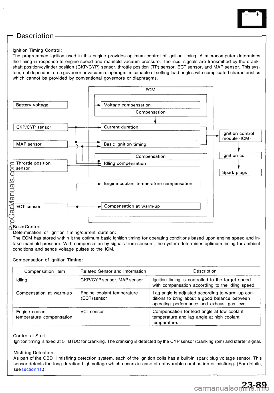
Ignition Timin g Control :
Th e programme d ignitio n use d i n thi s engin e provide s optimu m contro l o f ignitio n timing . A microcompute r determine s
th e timin g i n respons e t o engin e spee d an d manifol d vacuu m pressure . Th e inpu t signal s ar e transmitte d b y th e crank -
shaf t position/cylinde r positio n (CKP/CYP ) sensor , throttl e positio n (TP ) sensor , EC T sensor , an d MA P sensor . Thi s sys -
tem , no t dependen t o n a governo r o r vacuu m diaphragm , i s capabl e o f settin g lea d angle s wit h complicate d characteristic s
whic h canno t b e provide d b y conventiona l governor s o r diaphragms .
Basi c Contro l
Determinatio n of ignitio n timing/curren t duration :
Th e EC M ha s store d withi n i t th e optimu m basi c ignitio n timin g fo r operatin g condition s base d upo n engin e spee d an d in -
tak e manifol d pressure . Wit h compensatio n b y signal s fro m sensors , th e syste m determine s optimu m timin g fo r ambien t
condition s an d send s voltag e pulse s t o th e ICM .
Compensatio n o f Ignitio n Timing :
Compensatio n Ite m
Idlin g
Compensatio n a t warm-u p
Engin e coolan t
temperatur e compensatio nRelate
d Senso r an d Informatio n
CKP/CY P sensor , MA P senso r
Engin e coolan t temperatur e
(ECT) senso r
ECT senso r Descriptio
n
Ignitio n timin g i s controlle d t o th e targe t spee d
wit h compensatio n accordin g t o th e idlin g speed .
La g angl e i s adjuste d accordin g t o warm-u p con -
dition s t o brin g abou t a goo d balanc e betwee n
operatin g performanc e an d exhaus t ga s level .
Compensatio n fo r lea d angl e a t low coolan t
temperatur e an d la g angl e a t hig h coolan t
temperature .
Contro l a t Star t
Ignitio n timin g is fixe d a t 5 ° BTD C fo r cranking . Th e crankin g is detecte d b y th e CY P senso r (crankin g rpm ) an d starte r signal .
Misfirin g Detectio n
A s par t o f th e OB D II misfirin g detectio n system , eac h o f th e ignitio n coil s ha s a built-i n spar k plu g voltag e sensor . Thi s
senso r detect s th e lon g duratio n hig h voltag e whic h occur s i n cas e o f unfavorabl e combustio n o r misfiring . (Fo r details ,
se e sectio n 11 .)
ProCarManuals.com
Page 1262 of 1503
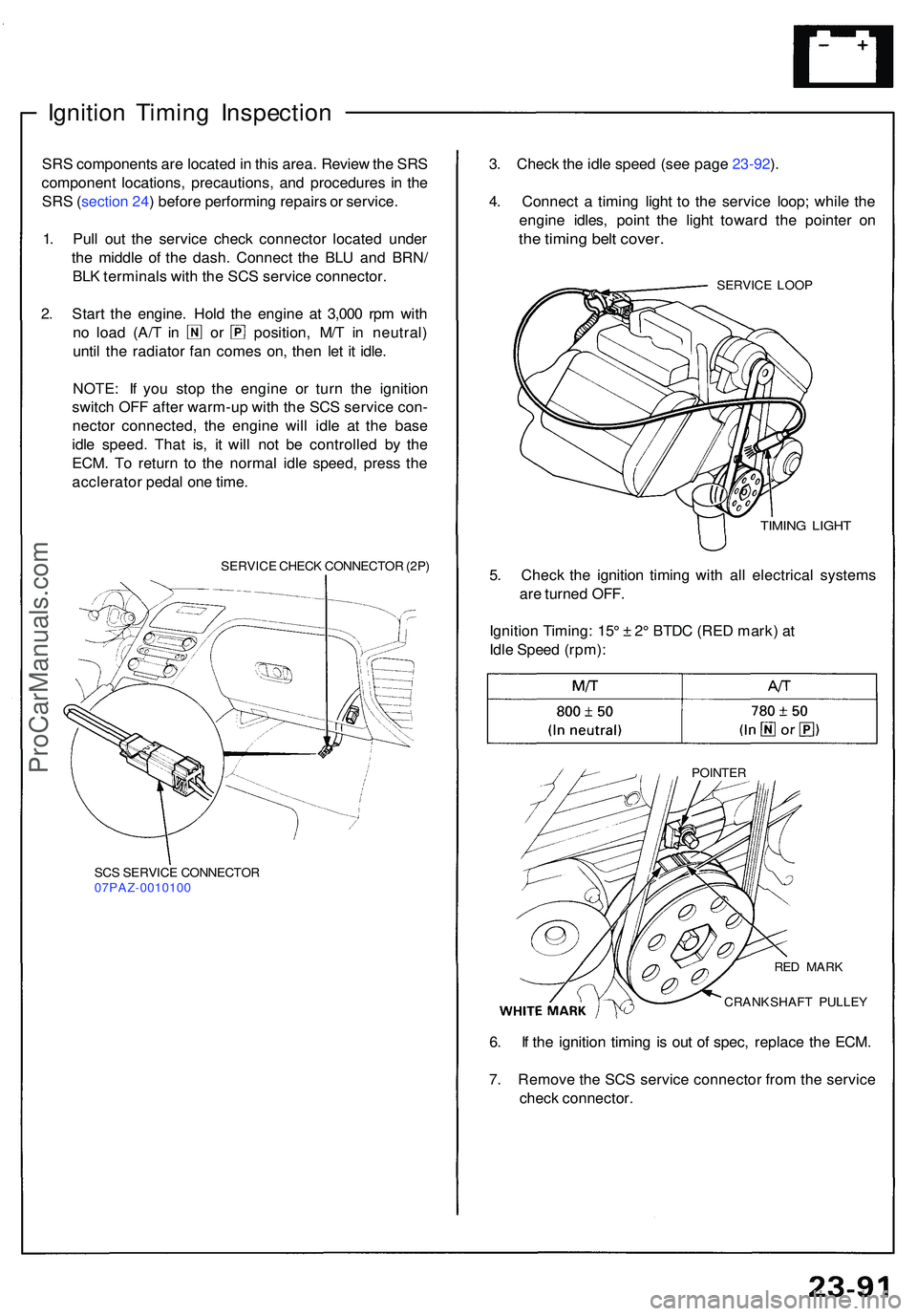
Ignition Timin g Inspectio n
SRS component s ar e locate d in thi s area . Revie w th e SR S
componen t locations , precautions , an d procedure s i n th e
SR S (sectio n 24 ) befor e performin g repair s o r service .
1 . Pul l ou t th e servic e chec k connecto r locate d unde r
th e middl e o f th e dash . Connec t th e BL U an d BRN /
BL K terminal s wit h th e SC S servic e connector .
2 . Star t th e engine . Hol d th e engin e a t 3,00 0 rp m wit h
no loa d (A/ T i n o r position , M/ T i n neutral )
unti l th e radiato r fa n come s on , the n le t i t idle .
NOTE : I f yo u sto p th e engin e o r tur n th e ignitio n
switc h OF F afte r warm-u p wit h th e SC S servic e con -
necto r connected , th e engin e wil l idl e a t th e bas e
idl e speed . Tha t is , i t wil l no t b e controlle d b y th e
ECM . T o retur n t o th e norma l idl e speed , pres s th e
acclerato r peda l on e time .
SERVIC E CHEC K CONNECTO R (2P )
SC S SERVIC E CONNECTO R
07PAZ-001010 0
3. Chec k th e idl e spee d (se e pag e 23-92 ).
4 . Connec t a timin g ligh t t o th e servic e loop ; whil e th e
engin e idles , poin t th e ligh t towar d th e pointe r o n
the timin g bel t cover .
SERVIC E LOO P
TIMIN G LIGH T
5. Chec k th e ignitio n timin g wit h al l electrica l system s
ar e turne d OFF .
Ignitio n Timing : 15 ° ± 2° BTD C (RE D mark ) a t
Idl e Spee d (rpm) :
POINTE R
6. I f th e ignitio n timin g i s ou t o f spec , replac e th e ECM .
7 . Remov e th e SC S servic e connecto r fro m th e servic e
chec k connector .
CRANKSHAF T PULLE Y
RE
D MAR K
ProCarManuals.com