1997 ACURA NSX ignition
[x] Cancel search: ignitionPage 1402 of 1503
Function Test
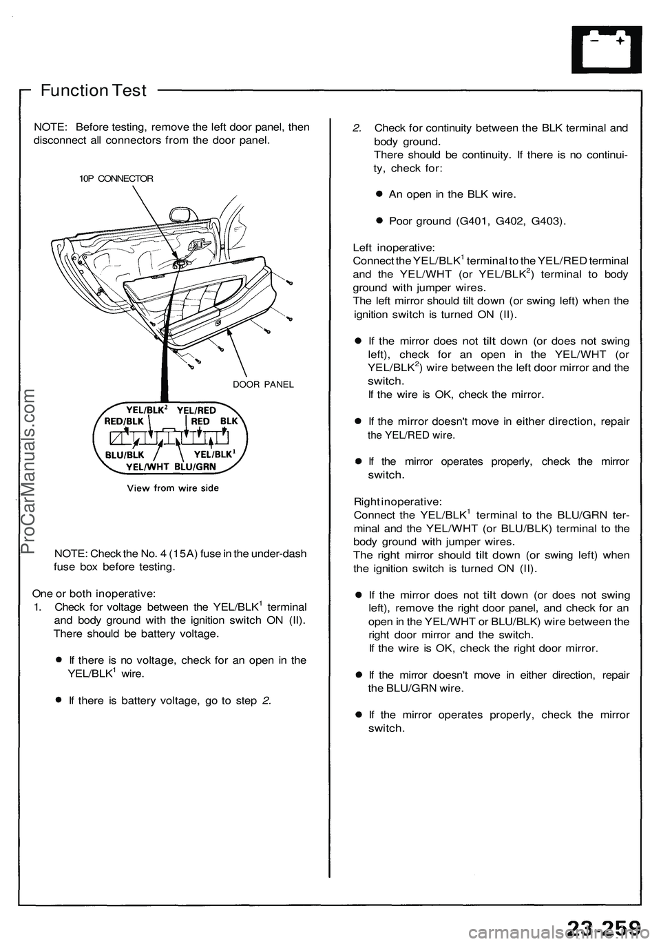
NOTE: Before testing, remove the left door panel, then
disconnect all connectors from the door panel.
10P CONNECTOR
DOOR PANEL
NOTE: Check the No. 4 (15A) fuse in the under-dash
fuse box before testing.
One or both inoperative:
1. Check for voltage between the YEL/BLK1 terminal
and body ground with the ignition switch ON (II).
There should be battery voltage.
If there is no voltage, check for an open in the
YEL/BLK1 wire.
If there is battery voltage, go to step 2.
2. Check for continuity between the BLK terminal and
body ground.
There should be continuity. If there is no continui-
ty, check for:
An open in the BLK wire.
Poor ground (G401, G402, G403).
Left inoperative:
Connect the YEL/BLK1 terminal to the YEL/RED terminal
and the YEL/WHT (or YEL/BLK2) terminal to body
ground with jumper wires.
The left mirror should tilt down (or swing left) when the
ignition switch is turned ON (II).
If the
mirror does
not
tilt
down
(or
does
not
swing
left), check for an open in the YEL/WHT (or
YEL/BLK2) wire between the left door mirror and the
switch.
If the wire is OK, check the mirror.
If the mirror doesn't move in either direction, repair
the YEL/RED wire.
If the mirror operates properly, check the mirror
switch.
Right inoperative:
Connect the YEL/BLK1 terminal to the BLU/GRN ter-
minal and the YEL/WHT (or BLU/BLK) terminal to the
body ground with jumper wires.
The
right
mirror should
tilt
down
(or
swing left) when
the ignition switch is turned ON (II).
If the
mirror does
not
tilt
down
(or
does
not
swing
left), remove the right door panel, and check for an
open in the YEL/WHT or BLU/BLK) wire between the
right door mirror and the switch.
If the wire is OK, check the right door mirror.
If the mirror doesn't move in either direction, repair
the BLU/GRN wire.
If the mirror operates properly, check the mirror
switch.ProCarManuals.com
Page 1409 of 1503
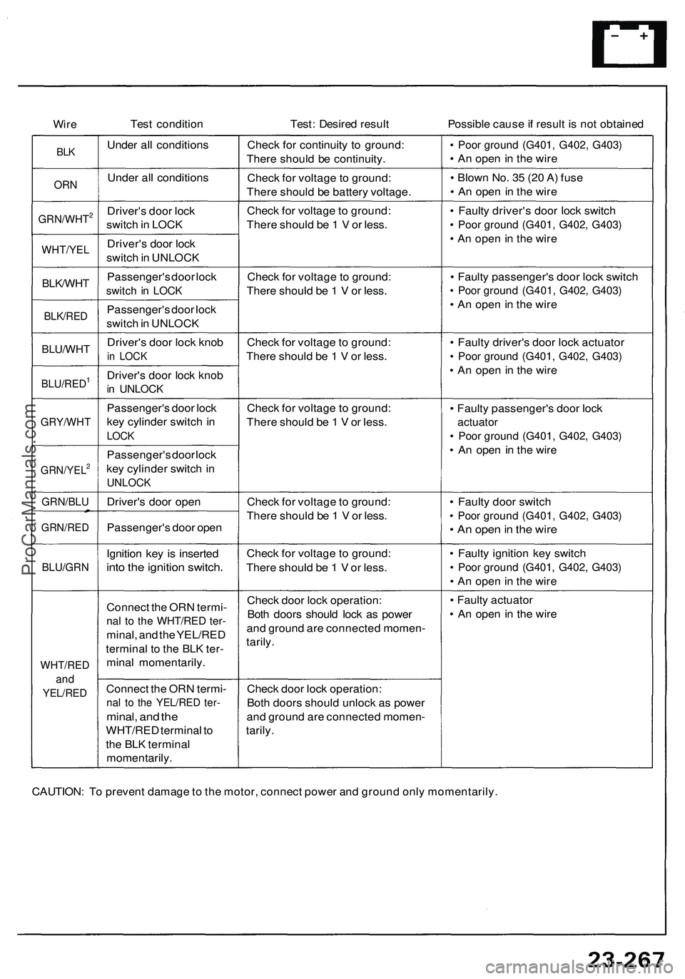
Wire
Test condition
Test: Desired result
Possible cause if result is not obtained
BLK
Under all conditions
Check for continuity to ground:
There should be continuity.
• Poor ground (G401, G402, G403)
• An open in the wire
ORN
Under all conditions
Check for voltage to ground:
There should be battery voltage.
• Blown No. 35 (20 A) fuse
• An open in the wire
GRN/WHT2
Driver's door lock
switch in LOCK
Check for voltage to ground:
There should be 1 V or less.
WHT/YEL
Driver's door lock
switch in UNLOCK
• Faulty driver's door lock switch
• Poor ground (G401, G402, G403)
• An open in the wire
BLK/WHT
Passenger's door lock
switch in LOCK
Check for voltage to ground:
There should be 1 V or less.
BLK/RED
Passenger's door lock
switch in UNLOCK
• Faulty passenger's door lock switch
• Poor ground (G401, G402, G403)
• An open in the wire
BLU/WHT
Driver's door lock knob
in LOCK
Check for voltage to ground:
There should be 1 V or less.
BLU/RED1
Driver's door lock knob
in UNLOCK
• Faulty driver's door lock actuator
• Poor ground (G401, G402, G403)
• An open in the wire
GRY/WHT
Passenger's door lock
key cylinder switch in
LOCK
Check for voltage to ground:
There should be 1 V or less.
GRN/YEL2
Passenger's door lock
key cylinder switch in
UNLOCK
• Faulty passenger's door lock
actuator
• Poor ground (G401, G402, G403)
• An open in the wire
GRN/BLU
Driver's door open
GRN/RED
Passenger's door open
Check for voltage to ground:
There should be 1 V or less.
• Faulty door switch
• Poor ground (G401, G402, G403)
• An open in the wire
BLU/GRN
Ignition key is inserted
into the ignition switch.
Check for voltage to ground:
There should be 1 V or less.
• Faulty ignition key switch
• Poor ground (G401, G402, G403)
• An open in the wire
WHT/RED
and
YEL/RED
Connect the ORN termi-
nal to the WHT/RED ter-
minal, and the YEL/RED
terminal to the BLK ter-
minal momentarily.
Check door lock operation:
Both doors should lock as power
and ground are connected momen-
tarily.
• Faulty actuator
• An open in the wire
Connect the ORN termi-
nal to the YEL/RED ter-
minal, and the
WHT/RED terminal to
the BLK terminal
momentarily.
Check door lock operation:
Both doors should unlock as power
and ground are connected momen-
tarily.
CAUTION: To prevent damage to the motor, connect power and ground only momentarily.ProCarManuals.com
Page 1415 of 1503
Power Windows
Control Unit Input Test
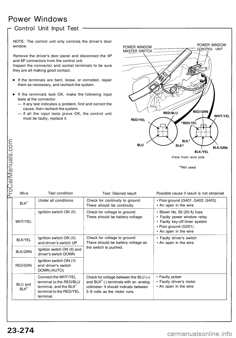
NOTE: The control unit only controls the driver's door
window.
Remove the driver's door panel and disconnect the 4P
and 6P connectors from the control unit.
Inspect the connector and socket terminals to be sure
they are all making good contact.
If the terminals are bent, loose, or corroded, repair
them as necessary, and recheck the system.
If the terminals look OK, make the following input
tests at the connector.
— If any test indicates a problem, find and correct the
cause, then recheck the system.
— If all the input tests prove OK, the control unit
must be faulty; replace it.
POWER WINDOW
MASTER SWITCH
POWER WINDOW
CONTROL UNIT
Wire
Test condition
Test: Desired result
Possible cause if result is not obtained
BLK1
Under all conditions
Check for continuity to ground:
There should be continuity.
• Poor ground (G401, G402, G403)
• An open in the wire
Ignition switch ON (II)
Check for voltage to ground:
There should be battery voltage.
WHT/YEL
• Blown No. 50 (20 A) fuse
• Faulty power window relay
• Faulty key-off timer system
• Poor ground (G201)
• An open in the wire
BLK/YEL
Ignition switch ON (II)
and driver's switch UP
BLK/GRN
Ignition switch ON (II) and
driver's switch DOWN
Check for voltage to ground:
There should be battery voltage as
the switch is pushed.
• Faulty driver's switch
• An open in the wire
RED/GRN
Ignition switch ON (
and driver's switch
DOWN (AUTO)
BLU and
BLK2
Connect the WHT/YEL
terminal to the RED/BLU
terminal, and the BLK1
terminal to the RED/YEL
terminal.
Check for voltage between the BLU (+)
and BLK2 (-) terminals with an analog
voltmeter: It should indicate between
3-8 volts as the motor runs.
• Faulty pulser
• Faulty driver's motor
• An open in the wireProCarManuals.com
Page 1430 of 1503
Rear Window Defogger
Function Test
CAUTION: Be careful not to scratch or damage the
defogger wires with the tester probe.
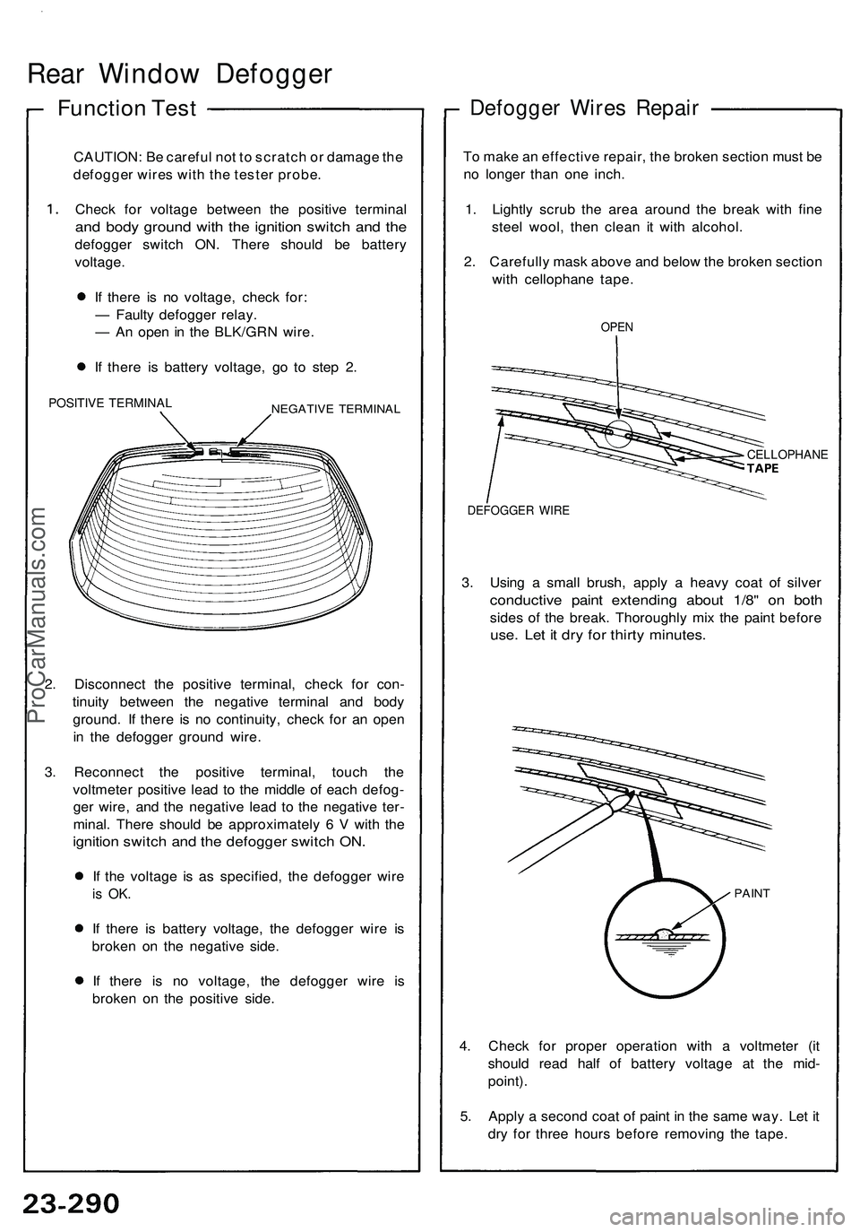
Check for voltage between the positive terminal
and body ground with the ignition switch and the
defogger switch ON. There should be battery
voltage.
If there is no voltage, check for:
— Faulty defogger relay.
— An open in the BLK/GRN wire.
If there is battery voltage, go to step 2.
POSITIVE TERMINAL
NEGATIVE TERMINAL
2. Disconnect the positive terminal, check for con-
tinuity between the negative terminal and body
ground. If there is no continuity, check for an open
in the defogger ground wire.
3. Reconnect the positive terminal, touch the
voltmeter positive lead to the middle of each defog-
ger wire, and the negative lead to the negative ter-
minal. There should be approximately 6 V with the
ignition switch and the defogger switch ON.
If the voltage is as specified, the defogger wire
is OK.
If there is battery voltage, the defogger wire is
broken on the negative side.
If there is no voltage, the defogger wire is
broken on the positive side.
Defogger Wires Repair
To make an effective repair, the broken section must be
no longer than one inch.
1. Lightly scrub the area around the break with fine
steel wool, then clean it with alcohol.
2. Carefully mask above and below the broken section
with cellophane tape.
OPEN
CELLOPHANE
DEFOGGER WIRE
3. Using a small brush, apply a heavy coat of silver
conductive paint extending about 1/8" on both
sides of the break. Thoroughly mix the paint before
use. Let it dry for thirty minutes.
PAINT
4. Check for proper operation with a voltmeter (it
should read half of battery voltage at the mid-
point).
5. Apply a second coat of paint in the same way. Let it
dry for three hours before removing the tape.ProCarManuals.com
Page 1445 of 1503
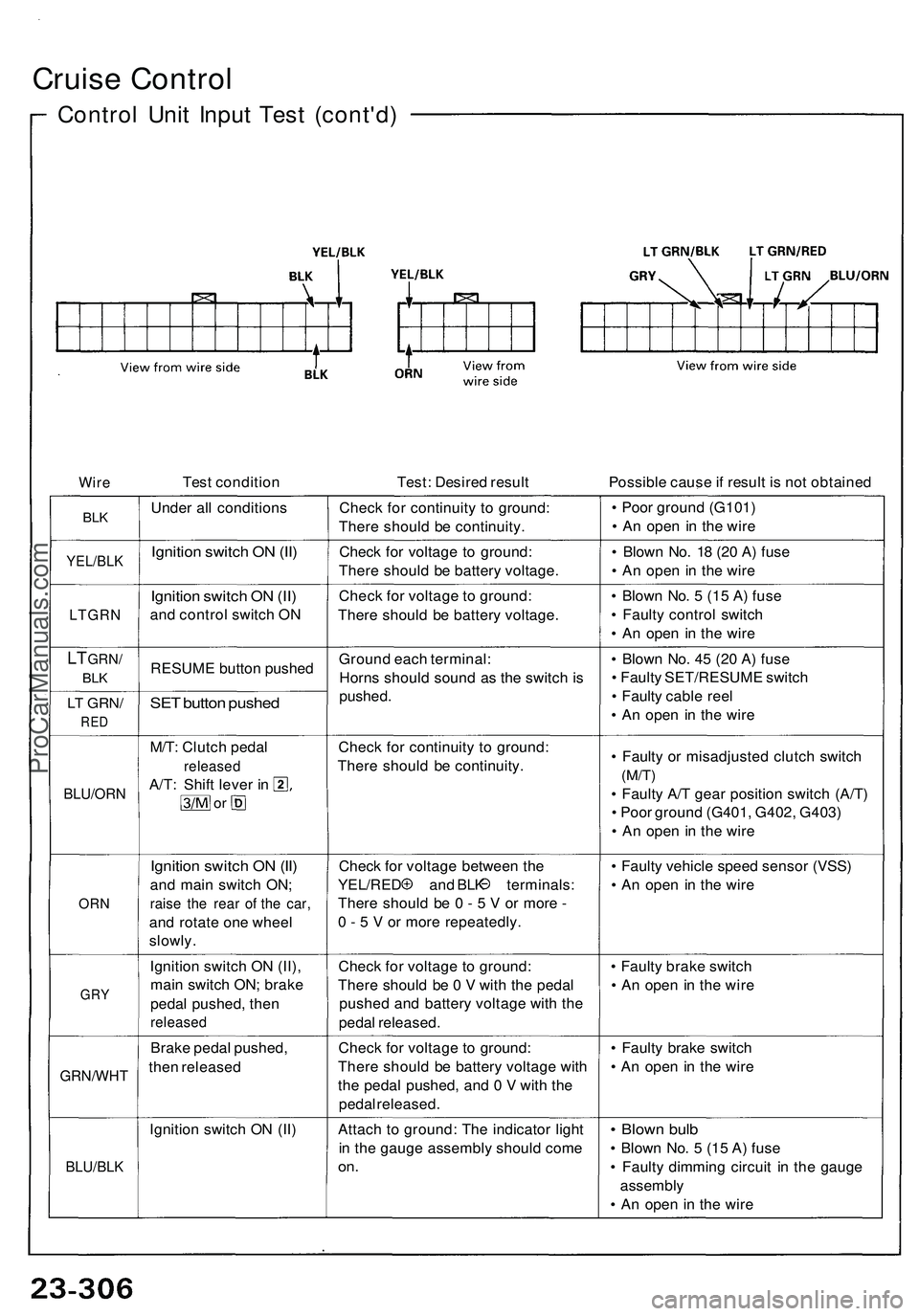
Cruise Contro l
Control Uni t Inpu t Tes t (cont'd )
WireTes t conditio n Test: Desire d resul t Possible caus e if resul t i s no t obtaine d
BLKUnde r al l condition sCheck fo r continuit y t o ground :
Ther e shoul d b e continuity . •
Poo r groun d (G101 )
• A n ope n i n th e wir e
YEL/BL KIgnition switc h O N (II )Chec k fo r voltag e t o ground :
Ther e shoul d b e batter y voltage . •
Blow n No . 1 8 (2 0 A ) fus e
• A n ope n i n th e wir e
LTGR N
Ignition switc h O N (II )
an d contro l switc h O N Chec
k fo r voltag e t o ground :
Ther e shoul d b e batter y voltage . •
Blow n No . 5 (1 5 A ) fus e
• Fault y contro l switc h
• A n ope n i n th e wir e
LT GRN /
BLKRESUM E butto n pushe d
LT GRN /
RED
SET butto n pushe d
Groun d eac h terminal :
Horn s shoul d soun d a s th e switc h i s
pushed . •
Blow n No . 4 5 (2 0 A ) fus e
• Fault y SET/RESUM E switc h
• Fault y cabl e ree l
• A n ope n i n th e wir e
BLU/OR N
M/T: Clutc h peda l
release d
A/T: Shif t leve r i n
o r
Chec k fo r continuit y t o ground :
Ther e shoul d b e continuity . •
Fault y o r misadjuste d clutc h switc h
(M/T)
• Fault y A/ T gea r positio n switc h (A/T )
• Poo r groun d (G401 , G402 , G403 )
• A n ope n i n th e wir e
ORN
Ignitio n switc h O N (II )
an d mai n switc h ON ;
raise th e rea r o f th e car ,
and rotat e on e whee l
slowly . Chec
k fo r voltag e betwee n th e
YEL/RE D an d BL K terminals :
Ther e shoul d b e 0 - 5 V or mor e -
0 - 5 V or mor e repeatedly . •
Fault y vehicl e spee d senso r (VSS )
• A n ope n i n th e wir e
GRY
Ignitio n switc h O N (II) ,
mai n switc h ON ; brak e
peda l pushed , the n
release d
Check fo r voltag e t o ground :
Ther e shoul d b e 0 V wit h th e peda l
pushe d an d batter y voltag e wit h th e
peda l released . •
Fault y brak e switc h
• A n ope n i n th e wir e
GRN/WH T
Brake peda l pushed ,
the n release d Chec
k fo r voltag e t o ground :
Ther e shoul d b e batter y voltag e wit h
th e peda l pushed , an d 0 V wit h th e
peda l released . •
Fault y brak e switc h
• A n ope n i n th e wir e
Ignitio n switc h O N (II )
BLU/BL K
Attach t o ground : Th e indicato r ligh t
i n th e gaug e assembl y shoul d com e
on.
• Blow n bul b
• Blow n No . 5 (1 5 A ) fus e
• Fault y dimmin g circui t i n th e gaug e
assembl y
• A n ope n i n th e wir e
ProCarManuals.com
Page 1456 of 1503
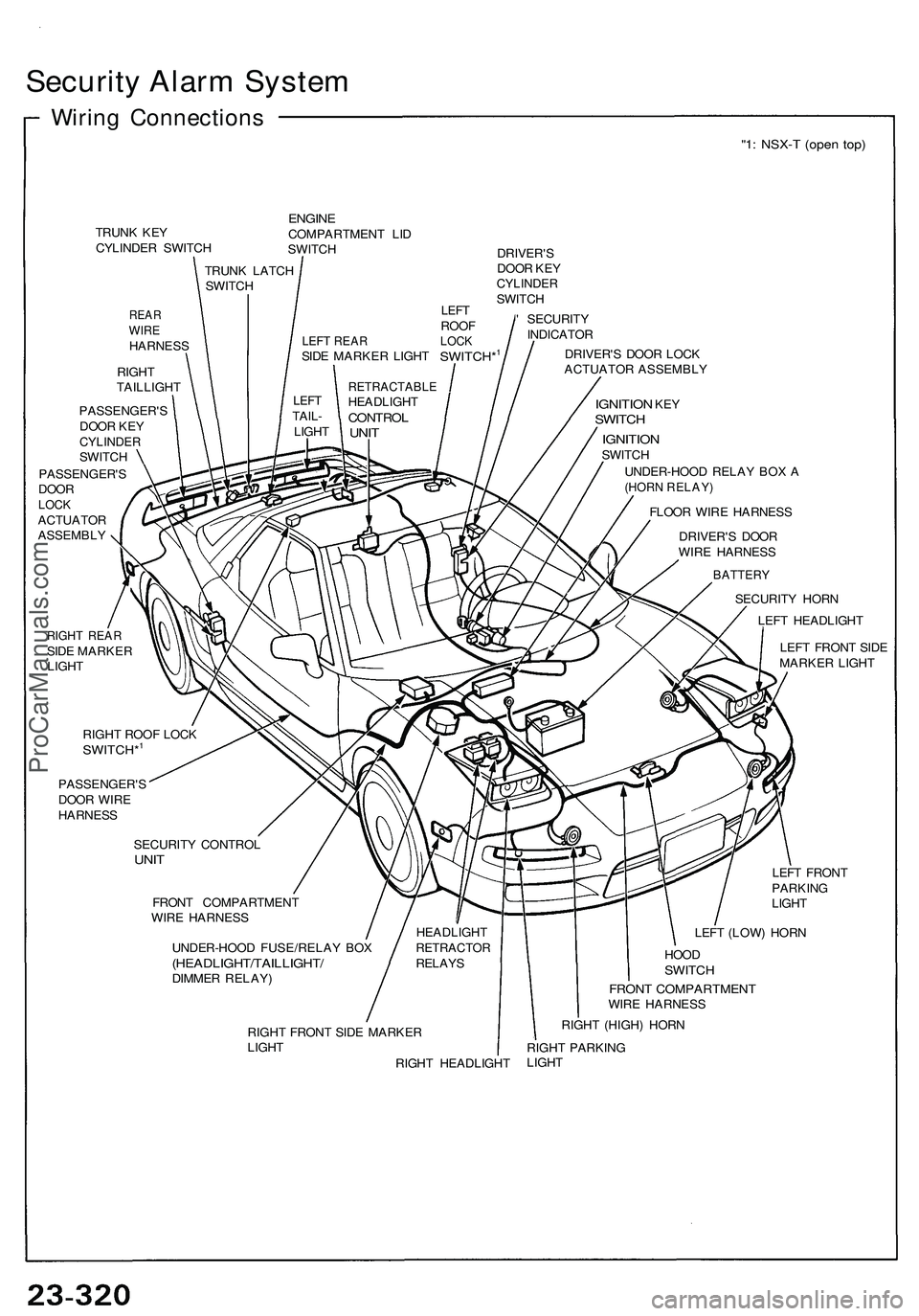
Security Alar m Syste m
Wiring Connection s
"1: NSX- T (ope n top )
TRUN K KE Y
CYLINDE R SWITC H
REARWIREHARNES S
RIGH T
TAILLIGH T
ENGINECOMPARTMEN T LI D
SWITC H
DRIVER'S
DOO R KE Y
CYLINDE RSWITCH
' SECURIT Y
INDICATO R
DRIVER' S DOO R LOC K
ACTUATO R ASSEMBL Y
PASSENGER' S
DOO R KE Y
CYLINDE RSWITCH
PASSENGER' S
DOO R
LOCKACTUATO R
ASSEMBL Y
IGNITION KEYSWITC H
IGNITIO NSWITCH
UNDER-HOO D RELA Y BO X A
(HOR N RELAY )
FLOOR WIR E HARNES S
DRIVER' S DOO R
WIR E HARNES S
RIGHT REA RSIDE MARKE R
LIGH T TRUN
K LATC H
SWITC H
RETRACTABL EHEADLIGHTCONTROLUNIT
LEF TTAIL -
LIGH T
HEADLIGHT
RETRACTO RRELAYS
BATTER Y
SECURIT Y HOR N
LEF T HEADLIGH T
LEF T FRON T SID E
MARKE R LIGH T
RIGH T ROO F LOC K
SWITCH*1
PASSENGER' S
DOO R WIR E
HARNES S
SECURIT Y CONTRO L
UNIT
FRON T COMPARTMEN T
WIR E HARNES S
UNDER-HOO D FUSE/RELA Y BO X
(HEADLIGHT/TAILLIGHT /DIMMER RELAY ) LEF
T FRON T
PARKIN G
LIGH T
LEF T (LOW ) HOR N
HOO DSWITC H
FRONT COMPARTMEN TWIRE HARNES S
RIGH T FRON T SID E MARKE R
LIGH T
RIGHT HEADLIGH TRIGH
T (HIGH ) HOR N
RIGH T PARKIN G
LIGH T
LEFT REA RSIDE MARKE R LIGH TSWITCH*1
LEFTROO FLOCK
ProCarManuals.com
Page 1459 of 1503
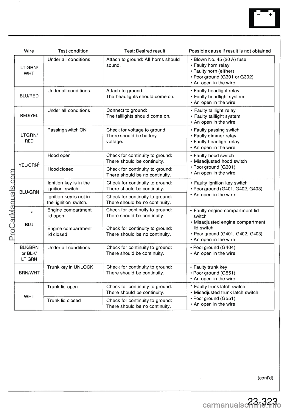
WireTes t conditio n Test: Desire d resul t Possible caus e if resul t i s no t obtaine d
LT GRN /
WHT
BLU/RE D
RED/YE L
LTGRN/
RED
YEL/GRN2
BLU/GR N
BLU
BLK/BR N
or BLK /
LT GR N
BRN/WH T
WHT
Unde r al l condition s
Unde r al l condition s
Unde r al l condition s
Passin g switc h O N
Hoo d ope n
Hoo d close d
Ignitio n ke y i s i n th e
ignitio n switch .
Ignition ke y is no t i n
th e ignitio n switch .
Engin e compartmen t
li d ope n
Engin e compartmen t
li d close d
Unde r al l condition s
Trun k ke y in UNLOC K
Trun k li d ope n
Trun k li d close d Attac
h t o ground : Al l horn s shoul d
sound .
Attac h t o ground :
Th e headlight s shoul d com e on .
Connec t t o ground :
Th e taillight s shoul d com e on .
Chec k fo r voltag e to ground :
Ther e shoul d b e batter y
voltage .
Check fo r continuit y t o ground :
Ther e shoul d b e continuity .
Chec k fo r continuit y t o ground :
Ther e shoul d b e n o continuity .
Chec k fo r continuit y t o ground :
Ther e shoul d b e continuity .
Chec k fo r continuit y t o ground :
Ther e shoul d b e n o continuity .
Chec k fo r continuit y t o ground :
Ther e shoul d b e continuity .
Chec k fo r continuit y t o ground :
Ther e shoul d b e n o continuity .
Chec k fo r continuit y t o ground :
Ther e shoul d b e continuity .
Chec k fo r continuit y t o ground :
Ther e shoul d b e continuity .
Chec k fo r continuit y t o ground :
Ther e shoul d b e continuity .
Chec k fo r continuit y t o ground :
Ther e shoul d b e n o continuity .•
Blow n No . 4 5 (2 0 A ) fus e
• Fault y hor n rela y
• Fault y hor n (either )
• Poo r groun d (G30 1 o r G302 )
• A n ope n i n th e wir e
• Fault y headligh t rela y
• Fault y headligh t syste m
• A n ope n in th e wir e
• Fault y tailligh t rela y
• Fault y tailligh t syste m
• A n ope n in th e wir e
• Fault y passin g switc h
• Fault y dimme r rela y
• Fault y headligh t rela y
• A n ope n i n th e wir e
• Fault y hoo d switc h
• Misadjuste d hoo d switc h
• Poo r groun d (G301 )
• A n ope n i n th e wir e
• Fault y ignitio n ke y switc h
• Poo r groun d (G401 , G402 , G403 )
• A n ope n in th e wir e
• Fault y engin e compartmen t li d
switc h
• Misadjuste d engin e compartmen t
li d switc h
• Poo r groun d (G401 , G402 , G403 )
• A n ope n in th e wir e
• Poo r groun d (G404 )
• A n ope n in th e wir e
• Fault y trun k ke y
• Poo r groun d (G551 )
• A n ope n i n th e wir e
* Fault y trun k latc h switc h
• Misadjuste d trun k latc h switc h
• Poo r groun d (G551 )
• A n ope n in th e wir e
(cont'd )
23-323ProCarManuals.com
Page 1464 of 1503
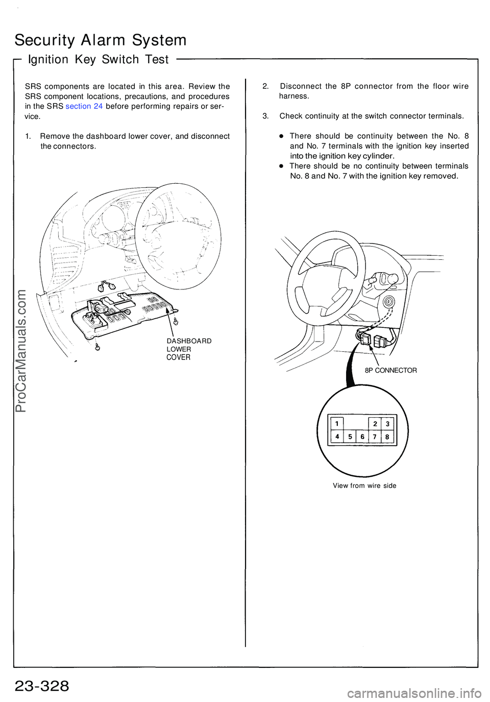
Security Alar m Syste m
Ignition Ke y Switc h Tes t
SRS component s ar e locate d i n thi s area . Revie w th e
SR S componen t locations , precautions , an d procedure s
i n th e SR S sectio n 24 befor e performin g repair s o r ser -
vice .
1. Remov e th e dashboar d lowe r cover , an d disconnec t
th e connectors .
DASHBOAR DLOWERCOVER
2. Disconnec t th e 8 P connecto r fro m th e floo r wir e
harness .
3. Chec k continuit y a t th e switc h connecto r terminals .
Ther e shoul d b e continuit y betwee n th e No . 8
an d No . 7 terminal s wit h th e ignitio n ke y inserte d
into th e ignitio n ke y cylinder .
There shoul d b e n o continuit y betwee n terminal s
No. 8 an d No . 7 wit h th e ignitio n ke y removed .
View fro m wir e sid e
23-32 8
8P CONNECTO R
ProCarManuals.com