1997 ACURA NSX transmission fluid
[x] Cancel search: transmission fluidPage 371 of 1503

4-2
For the details of lubrication points and types of lubricants to be appl\
ied, refer to the illustrated index and various work
procedures (such as Assembly/Reassembly, Replacement, Overhaul, Install\
ation, etc.) contained in each section.
*1: Always use Honda Manual Transmission Fluid (MTF). Using motor oil can \
cause stiffer shifting because it does not contain theproper additives.
*2: Always use Honda ATF-Z1 (ATF). Using a non-Honda ATF can affect shift \
quality.
*3: Always use Honda Heavy Duty DOT3 Brake Fluid. Using a non-Honda brake fl\
uid can cause corrosion and decrease the life of the system.
Lubrication Points
No.LUBRICATION POINTSLUBRICANT
1Honda Motor Oil: P/N 08798-9015.
Look for the API Certification seal shown below. Make sure
it says “For Gasoline Engines.”
2TransmissionHonda MTF*1(P/N 08798-9016)
3Brake system (including anti-lock brake system)Honda Heavy Duty DOT3 Brake Fluid*3(P/N 08798-9008)4Clutch line
5Change lever pivots (M/T)Super High Temp Urea Grease (P/N 08798-9002)6Release fork (M/T)
8
9
10
11
12
13
14
15
16
17
18
19
20
21Steering boots
Steering ball joints
Select lever (A/T)
Pedal linkage
Intermediate shaft
Brake master power pushrod
Fuel fill door
Clutch master cylinder pushrod
Tilt lever
Parking brake cable end
Door hinges upper and lower
Door opening detents
Hood hinges and lock
Rear hatch latch
Multipurpose grease
24
22
23
Caliper piston boot, caliper pins, and boots
Shift cable end and select cable end (A/T)
Throttle cable ends
Honda Caliper Grease (P/N 08C30-B0234M)
Silicone grease
25Air conditioning compressorCompressor oil:
DENSO: ND-OIL8 (P/N 38897-PR7-A01AH or 38899-PR7-A01)
For Refrigerant: HFC-134a (R-134a)
Manual
Honda ATF-Z1 (ATF)*2(P/N 08200-9001)Automatic
7Steering gearboxSteering grease (P/N 08733-B070E)
Engine
API CERTIFICATION SEAL
Recommended engine oil
Engine oil viscosity for
ambient temperature ranges
*05-NSX (61SW004)SEC04(01-10) 9/22/04 1:49 PM Page 4-2
ProCarManuals.com
Page 374 of 1503

4-5
Y
Do the items in parts A, B, C, D, E, F, and G as required for the mileag\
e/time interval listed.
NOTE: According to state and federal regulations, failure to do the maintenanc\
e items marked with an asterisk (*) will not
void the customer ’s emissions warranties. However, Acura recommends that all maintenance s\
ervices be done at
the recommended interval to ensure long-term reliability.
*1: Refer to the 1997 NSX Service Manual, P/N 61SL006.
*2: Refer to the 1998 NSX Service Manual Supplement, P/N 61SL007.
*3: Refer to the 2001 NSX Service Manual Supplement, P/N 61SW000.
A
B Replace engine oil (see page
8-2)*
2, every 7,500 miles (12,000 km) or 1 year.
Engine oil capacity: without oil filter: 4.3 L (4.5 US qt).
Check tire inflation and condition at least once a month, every 7,500 mi\
les (12,000 km).
Replace engine oil filter (see page 8-5)*1, every 15,000 miles (24,000 km) or 1 year.
Engine oil capacity: with oil filter: 5.0 L (5.3 US qt).
Check front and rear brake wear (see page 19-4)*1, every 15,000 miles (24,000 km) or 1 year.
• Check pads and discs for wear (thickness), damage, and cracks.
• Check calipers for damage, leaks, and tightness of mounting bolts.
Check parking brake adjustment (see page 19-5)*1, every 15,000 miles (24,000 km) or 1 year.
Check the number of clicks (10 to 14) when the parking brake lever is pulled with 196 N (20 kgf,\
44 lbf) of force.
Inspect tie-rod ends, steering gearbox, and gearbox boots (see page 17-57)*1, every 15,000 miles (24,000 km) or 1 year.
• Check rack grease and steering linkage.
• Check boots for damage and leaking grease.
• Check fluid lines for damage and leaks.1
• Check bolts for tightness.
• Check condition of ball joint boots for deterioration and damage.
Inspect driveshaft boots (see page 16-3)*1, every 15,000 miles (24,000 km) or 1 year.
Check boots for cracks and boot bands for tightness.
Inspect brake hoses and lines including ABS (see page 19-27)*1, every 15,000 miles (24,000 km) or 1 year.
Check the master cylinder, proportioning control valve and ABS modulator\
for damage and leakage.
Inspect all fluid levels and condition of fluids, every 15,000 miles (2\
4,000 km) or 1 year.
• Manual transmission fluid (MTF) (see page 13-3)*
1.
• Automatic transmission fluid (ATF-Z1) (see page 14-105)*1.
• Engine coolant (see page 10-2)*1.
• Brake fluid (see page 19-84)*1.
• Windshield washer fluid.
Cooling system hoses and connections (see page 10-2)*1, every 15,000 miles (24,000 km) or 1 year.
• Check all hoses for damage, leaks and deterioration.
• Check for proper fan operation.
Inspect exhaust system (see page 9-6)*, *1, every 15,000 miles (24,000 km) or 1 year.
Check catalytic converter heat shield, exhaust pipe, and muffler for dam\
age, leaks, and tightness ( see page 9-14 ).
Inspect fuel lines and connections (see page 11-130)*, *1, every 15,000 miles (24,000 km) or 1 year.
Check for loose connections, cracks, and deterioration; retighten loose \
connections and replace damaged parts.
Part Maintenance Items
*05-NSX (61SW004)SEC04(01-10) 9/22/04 1:49 PM Page 4-5
Inspect suspension components (see page 18-14)* , every 15,000 miles (24,000 km) or 1 year.
ProCarManuals.com
Page 375 of 1503
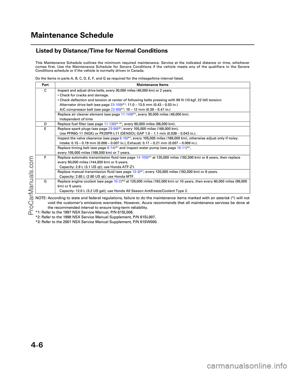
4-6
This Maintenance Schedule outlines the minimum required maintenance. Ser\
vice at the indicated distance or time, whichever
comes first. Use the Maintenance Schedule for Severe Conditions if the v\
ehicle meets any of the qualifiers in the Severe
Conditions schedule or if the vehicle is normally driven in Canada.
Do the items in parts A, B, C, D, E, F, and G as required for the mileag\
e/time interval listed.
NOTE: According to state and federal regulations, failure to do the maintenanc\
e items marked with an asterisk (*) will not
void the customer ’s emissions warranties. However, Acura recommends that all maintenance s\
ervices be done at
the recommended interval to ensure long-term reliability.
*1: Refer to the 1997 NSX Service Manual, P/N 61SL006.
*2: Refer to the 1998 NSX Service Manual Supplement, P/N 61SL007.
*3: Refer to the 2001 NSX Service Manual Supplement, P/N 61SW000.
C
D
E
F
G Inspect and adjust drive belts, every 30,000 miles (48,000 km) or 2 ye\
ars.
•
Check for cracks and damage.
• Check deflection and tension at center of following belts pressing with\
98 N (10 kgf, 22 lbf) tension:
Alternator drive belt (see page 23-109)*
1: 11.0 – 13.5 mm (0.43 – 0.53 in.)
A/C compressor belt (see page 22-88)*1: 10 – 12 mm (0.39 – 0.47 in.)
Replace air cleaner element (see page 11-149)*1, every 30,000 miles (48,000 km).
Independent of time
Replace fuel filter (see page 11-138)*, *1, every 60,000 miles (96,000 km).
Replace spark plugs (see page 23-96)*1, every 105,000 miles (168,000 km).
Use PFR6G-11 (NGK) or PK20PR-L11 (DENSO); GAP 1.0 – 1.1 mm (0.039 – 0.043 in.).
Inspect the valve clearance (see page 6-10)*1, every 105,000 miles (168,000 km), otherwise adjust only if noisy.
Intake: 0.15 – 0.19 mm (0.006 – 0.007 in.), Exhaust: 0.17 – 0.21 mm (0.007 – 0.008 in.).
Replace timing belt (see page 6-14)*1 and inspect water pump (see page 10-11)*1,
every 105,000 miles (168,000 km) or 7 years.
Replace automatic transmission fluid (see page 14-105)*1 at 120,000 miles (192,000 km) or 6 years, then replace
every 90,000 miles (144,000 km) or 5 years.
Capacity: 2.9 L (3.1 US qt); use Honda ATF-Z1.
Replace manual transmission fluid (see page 13-3)*1, every 120,000 miles (192,000 km) or 6 years.
Capacity: 2.65 L (2.80 US qt); use Honda MTF.
Replace engine coolant (see page 10-2 )*3 at 120,000 miles (192,000 km) or 10 years, then every 60,000 miles (9\
6,000
km) or 5 years. Capacity: 12.0 L (3.2 US gal); use Honda All Season Antifreeze/Coolant\
Type 2.
Part Maintenance Items
Maintenance Schedule
Listed by Distance/Time for Normal Conditions
*05-NSX (61SW004)SEC04(01-10) 9/22/04 1:49 PM Page 4-6
ProCarManuals.com
Page 713 of 1503
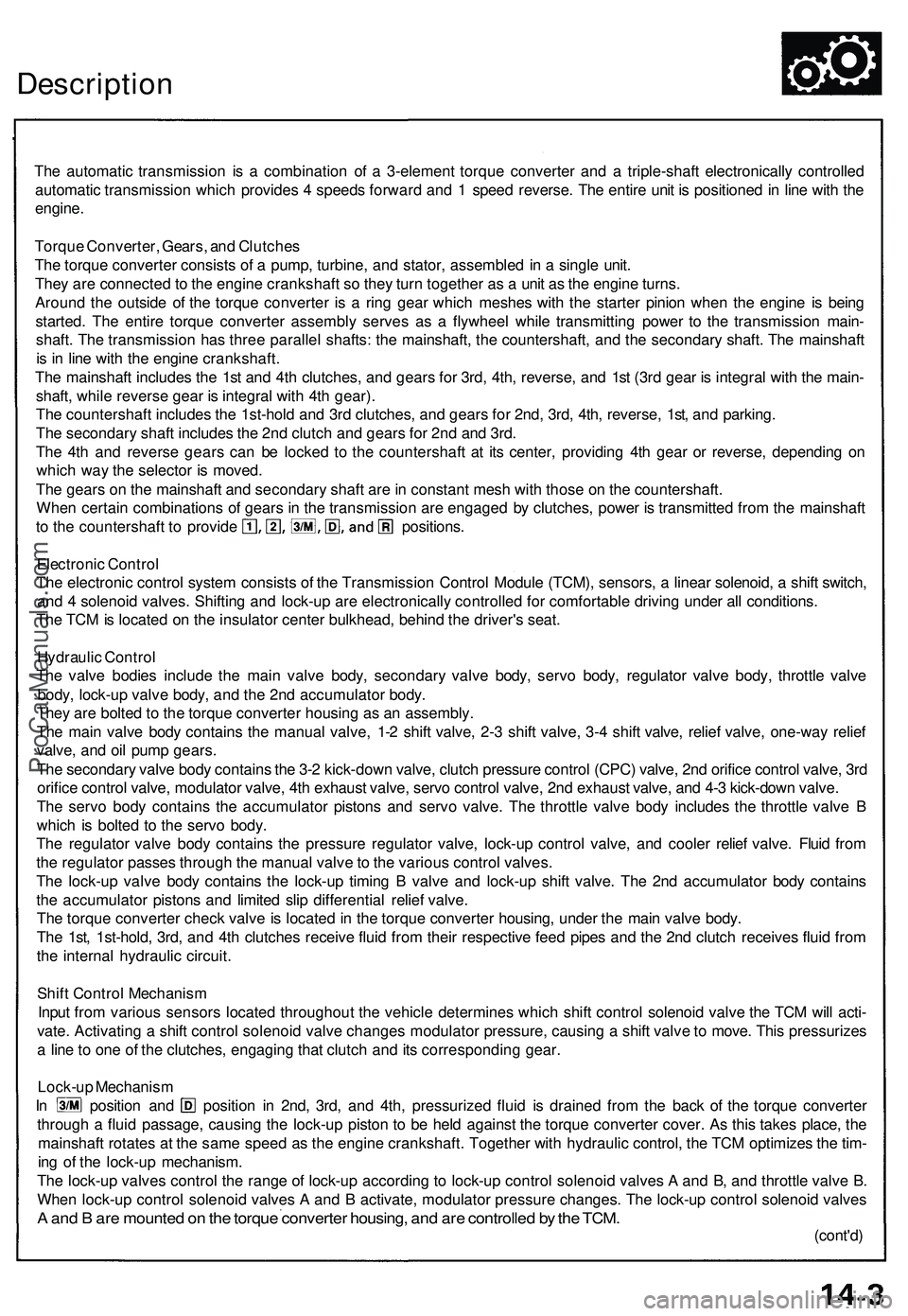
Description
The automatic transmission is a combination of a 3-element torque converter and a triple-shaft electronically controlled
automatic transmission which provides 4 speeds forward and 1 speed reverse. The entire unit is positioned in line with the
engine.
Torque Converter, Gears, and Clutches
The torque converter consists of a pump, turbine, and stator, assembled in a single unit.
They are connected to the engine crankshaft so they turn together as a unit as the engine turns.
Around the outside of the torque converter is a ring gear which meshes with the starter pinion when the engine is being
started. The entire torque converter assembly serves as a flywheel while transmitting power to the transmission main-
shaft. The transmission has three parallel shafts: the mainshaft, the countershaft, and the secondary shaft. The mainshaft
is in line with the engine crankshaft.
The mainshaft includes the 1st and 4th clutches, and gears for 3rd, 4th, reverse, and 1st (3rd gear is integral with the main-
shaft, while reverse gear is integral with 4th gear).
The countershaft includes the 1st-hold and 3rd clutches, and gears for 2nd, 3rd, 4th, reverse, 1st, and parking.
The secondary shaft includes the 2nd clutch and gears for 2nd and 3rd.
The 4th and reverse gears can be locked to the countershaft at its center, providing 4th gear or reverse, depending on
which way the selector is moved.
The gears on the mainshaft and secondary shaft are in constant mesh with those on the countershaft.
When certain combinations of gears in the transmission are engaged by clutches, power is transmitted from the mainshaft
to the countershaft to provide positions.
Electronic Control
The electronic control system consists of the Transmission Control Module (TCM), sensors, a linear solenoid, a shift switch,
and 4 solenoid valves. Shifting and lock-up are electronically controlled for comfortable driving under all conditions.
The TCM is located on the insulator center bulkhead, behind the driver's seat.
Hydraulic Control
The valve bodies include the main valve body, secondary valve body, servo body, regulator valve body, throttle valve
body, lock-up valve body, and the 2nd accumulator body.
They are bolted to the torque converter housing as an assembly.
The main valve body contains the manual valve, 1-2 shift valve, 2-3 shift valve, 3-4 shift valve, relief valve, one-way relief
valve, and oil pump gears.
The secondary valve body contains the 3-2 kick-down valve, clutch pressure control (CPC) valve, 2nd orifice control valve, 3rd
orifice control valve, modulator valve, 4th exhaust valve, servo control valve, 2nd exhaust valve, and 4-3 kick-down valve.
The servo body contains the accumulator pistons and servo valve. The throttle valve body includes the throttle valve B
which is bolted to the servo body.
The regulator valve body contains the pressure regulator valve, lock-up control valve, and cooler relief valve. Fluid from
the regulator passes through the manual valve to the various control valves.
The lock-up valve body contains the lock-up timing B valve and lock-up shift valve. The 2nd accumulator body contains
the accumulator pistons and limited slip differential relief valve.
The torque converter check valve is located in the torque converter housing, under the main valve body.
The 1st, 1st-hold, 3rd, and 4th clutches receive fluid from their respective feed pipes and the 2nd clutch receives fluid from
the internal hydraulic circuit.
Shift Control Mechanism
Input from various sensors located throughout the vehicle determines which shift control solenoid valve the TCM will acti-
vate. Activating a shift control solenoid valve changes modulator pressure, causing a shift valve to move. This pressurizes
a line to one of the clutches, engaging that clutch and its corresponding gear.
Lock-up Mechanism
In position and position in 2nd, 3rd, and 4th, pressurized fluid is drained from the back of the torque converter
through a fluid passage, causing the lock-up piston to be held against the torque converter cover. As this takes place, the
mainshaft rotates at the same speed as the engine crankshaft. Together with hydraulic control, the TCM optimizes the tim-
ing of the lock-up mechanism.
The lock-up valves control the range of lock-up according to lock-up control solenoid valves A and B, and throttle valve B.
When lock-up control solenoid valves A and B activate, modulator pressure changes. The lock-up control solenoid valves
A and B are mounted on the torque converter housing, and are controlled by the TCM.
(cont'd)ProCarManuals.com
Page 727 of 1503
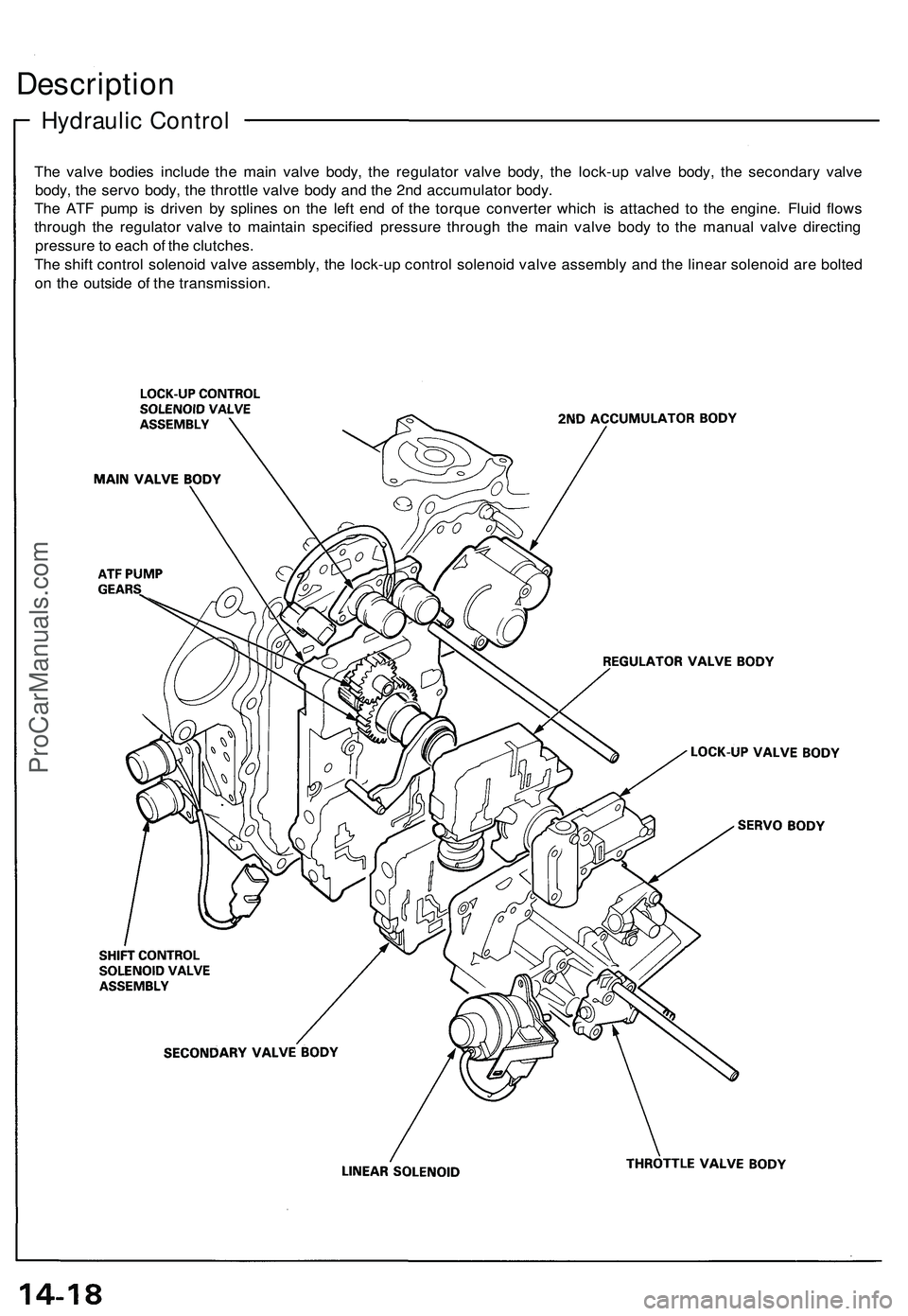
Hydraulic Control
Description
The valve bodies include the main valve body, the regulator valve body, the lock-up valve body, the secondary valve
body, the servo body, the throttle valve body and the 2nd accumulator body.
The ATF pump is driven by splines on the left end of the torque converter which is attached to the engine. Fluid flows
through the regulator valve to maintain specified pressure through the main valve body to the manual valve directing
pressure to each of the clutches.
The shift control solenoid valve assembly, the lock-up control solenoid valve assembly and the linear solenoid are bolted
on the outside of the transmission.ProCarManuals.com
Page 773 of 1503
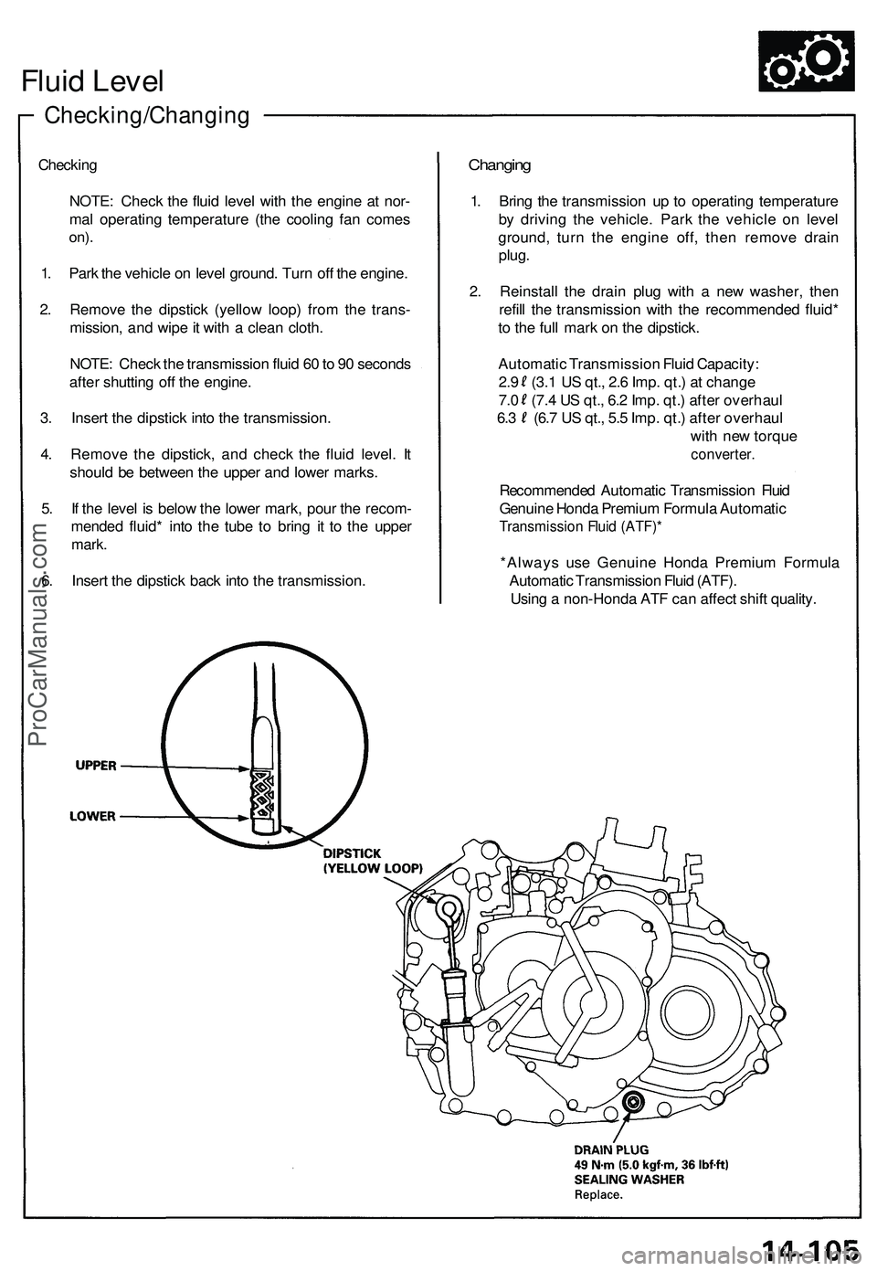
Checking/Changing
Fluid Leve l
Checkin g
NOTE : Chec k th e flui d leve l wit h th e engin e a t nor -
ma l operatin g temperatur e (th e coolin g fa n come s
on).
1. Par k th e vehicl e o n leve l ground . Tur n of f th e engine .
2 . Remov e th e dipstic k (yello w loop ) fro m th e trans -
mission , an d wip e it wit h a clea n cloth .
NOTE : Chec k th e transmissio n flui d 6 0 to 9 0 second s
afte r shuttin g of f th e engine .
3 . Inser t th e dipstic k int o th e transmission .
4 . Remov e th e dipstick , an d chec k th e flui d level . I t
shoul d b e betwee n th e uppe r an d lowe r marks .
5 . I f th e leve l i s belo w th e lowe r mark , pou r th e recom -
mende d fluid * int o th e tub e t o brin g i t t o th e uppe r
mark.
6. Inser t th e dipstic k bac k int o th e transmission .
Changing
1. Brin g th e transmissio n u p t o operatin g temperatur e
b y drivin g th e vehicle . Par k th e vehicl e o n leve l
ground , tur n th e engin e off , the n remov e drai n
plug .
2 . Reinstal l th e drai n plu g wit h a ne w washer , the n
refil l th e transmissio n wit h th e recommende d fluid *
t o th e ful l mar k o n th e dipstick .
Automati c Transmissio n Flui d Capacity :
2. 9 (3. 1 U S qt. , 2. 6 Imp . qt. ) a t chang e
7. 0 (7. 4 U S qt. , 6. 2 Imp . qt. ) afte r overhau l
6.3 (6. 7 U S qt. , 5. 5 Imp . qt. ) afte r overhau l
wit h ne w torqu e
converter .
Recommende d Automati c Transmissio n Fluid
Genuin e Hond a Premiu m Formul a Automati c
Transmissio n Flui d (ATF) *
*Alway s us e Genuin e Hond a Premiu m Formul a
Automati c Transmissio n Flui d (ATF) .
Usin g a non-Hond a AT F ca n affec t shif t quality .
ProCarManuals.com
Page 866 of 1503
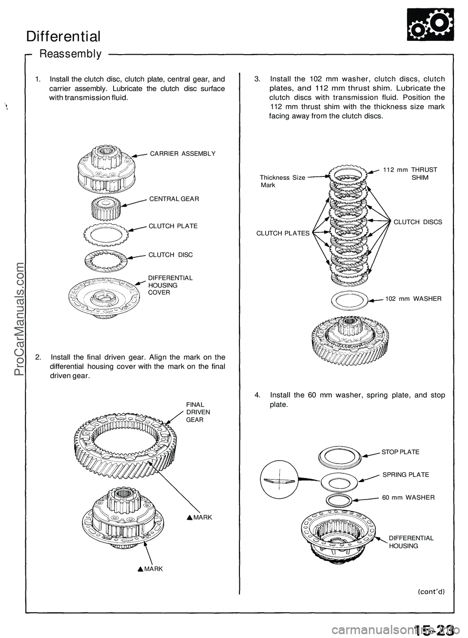
1. Install the clutch disc, clutch plate, central gear, and
carrier assembly. Lubricate the clutch disc surface
with transmission fluid.
CARRIER ASSEMBLY
CENTRAL GEAR
CLUTCH PLATE
CLUTCH DISC
DIFFERENTIAL
HOUSING
COVER
2. Install the final driven gear. Align the mark on the
differential housing cover with the mark on the final
driven gear.
FINAL
DRIVEN
GEAR
MARK
MARK
3. Install the 102 mm washer, clutch discs, clutch
plates, and 112 mm thrust shim. Lubricate the
clutch discs with transmission fluid. Position the
112 mm thrust shim with the thickness size mark
facing away from the clutch discs.
Thickness Size
Mark
CLUTCH PLATES
112 mm THRUST
SHIM
CLUTCH DISCS
102 mm WASHER
4. Install the 60 mm washer, spring plate, and stop
plate.
STOP PLATE
SPRING PLATE
60 mm WASHER
DIFFERENTIAL
HOUSING
Differential
ReassemblyProCarManuals.com