1997 ACURA NSX ignition
[x] Cancel search: ignitionPage 611 of 1503
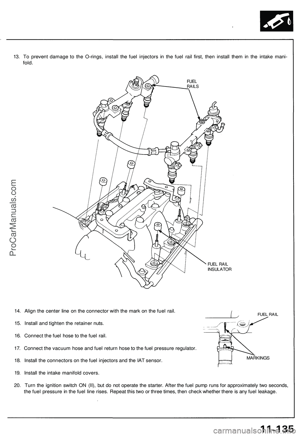
13. To prevent damage to the O-rings, install the fuel injectors in the fuel rail first, then install them in the intake mani-
fold.
FUEL
RAILS
FUEL RAIL
INSULATOR
FUEL RAIL
14. Align the center line on the connector with the mark on the fuel rail.
15. Install and tighten the retainer nuts.
16. Connect the fuel hose to the fuel rail.
17. Connect the vacuum hose and fuel return hose to the fuel pressure regulator.
18. Install the connectors on the fuel injectors and the IAT sensor.
19. Install the intake manifold covers.
20. Turn the ignition switch ON (II), but do not operate the starter. After the fuel pump runs for approximately two seconds,
the fuel pressure in the fuel line rises. Repeat this two or three times, then check whether there is any fuel leakage.
MARKINGSProCarManuals.com
Page 617 of 1503
PGM-FI Main Relay
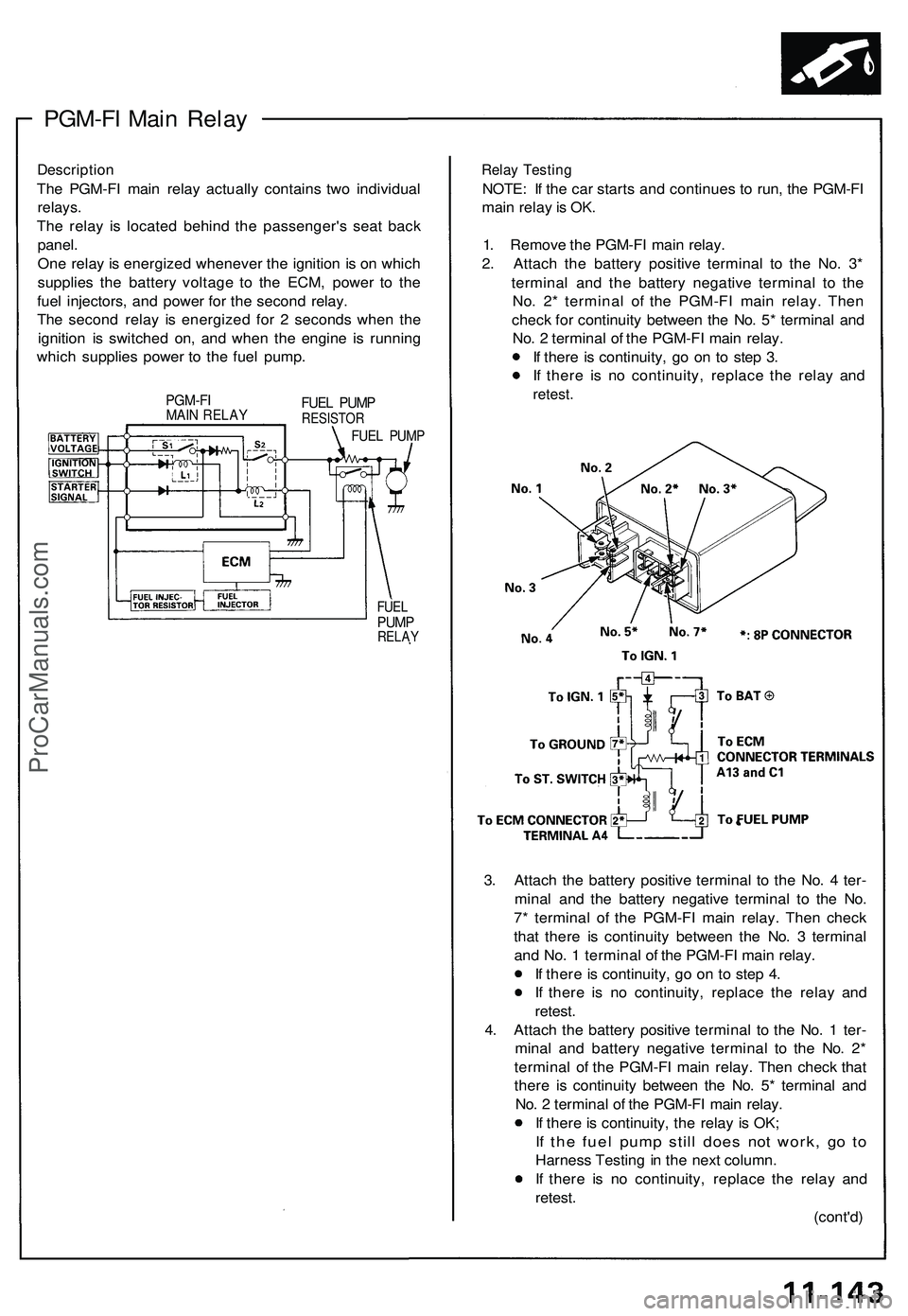
Description
The PGM-FI main relay actually contains two individual
relays.
The relay is located behind the passenger's seat back
panel.
One relay is energized whenever the ignition is on which
supplies the battery voltage to the ECM, power to the
fuel injectors, and power for the second relay.
The second relay is energized for 2 seconds when the
ignition is switched on, and when the engine is running
which supplies power to the fuel pump.
PGM-FI
MAIN RELAY
FUEL PUMP
RESISTOR
FUEL PUMP
FUEL
PUMP
RELAY
Relay Testing
NOTE: If the car starts and continues to run, the PGM-FI
main relay is OK.
1. Remove the PGM-FI main relay.
2. Attach the battery positive terminal to the No. 3*
terminal and the battery negative terminal to the
No. 2* terminal of the PGM-FI main relay. Then
check for continuity between the No. 5* terminal and
No. 2 terminal of the PGM-FI main relay.
If there is continuity, go on to step 3.
If there is no continuity, replace the relay and
retest.
3. Attach the battery positive terminal to the No. 4 ter-
minal and the battery negative terminal to the No.
7* terminal of the PGM-FI main relay. Then check
that there is continuity between the No. 3 terminal
and No. 1 terminal of the PGM-FI main relay.
If there is continuity, go on to step 4.
If there is no continuity, replace the relay and
retest.
4. Attach the battery positive terminal to the No. 1 ter-
minal and battery negative terminal to the No. 2*
terminal of the PGM-FI main relay. Then check that
there is continuity between the No. 5* terminal and
No. 2 terminal of the PGM-FI main relay.
If there is continuity, the relay is OK;
If the fuel pump still does not work, go to
Harness Testing in the next column.
If there is no continuity, replace the relay and
retest.
(cont'd)ProCarManuals.com
Page 901 of 1503
System Description
Function and Operation (cont'd)
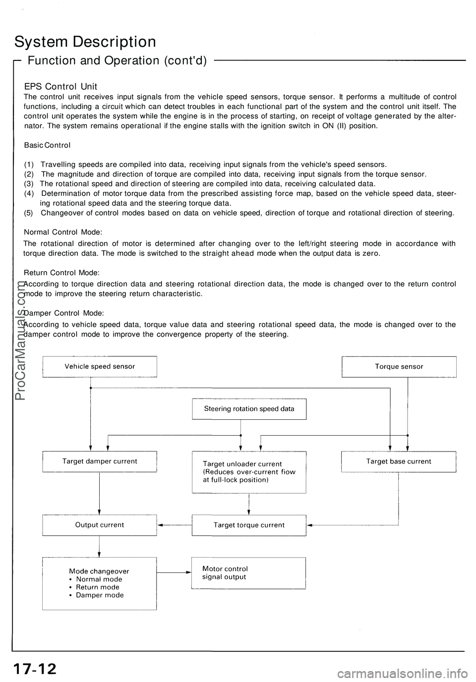
EPS Control Unit
The control unit receives input signals from the vehicle speed sensors, torque sensor. It performs a multitude of control
functions, including a circuit which can detect troubles in each functional part of the system and the control unit itself. The
control unit operates the system while the engine is in the process of starting, on receipt of voltage generated by the alter-
nator. The system remains operational if the engine stalls with the ignition switch in ON (II) position.
Basic Control
(1) Travelling speeds are compiled into data, receiving input signals from the vehicle's speed sensors.
(2) The magnitude and direction of torque are compiled into data, receiving input signals from the torque sensor.
(3) The rotational speed and direction of steering are compiled into data, receiving calculated data.
(4) Determination of motor torque data from the prescribed assisting force map, based on the vehicle speed data, steer-
ing rotational speed data and the steering torque data.
(5) Changeover of control modes based on data on vehicle speed, direction of torque and rotational direction of steering.
Normal Control Mode:
The rotational direction of motor is determined after changing over to the left/right steering mode in accordance with
torque direction data. The mode is switched to the straight ahead mode when the output data is zero.
Return Control Mode:
According to torque direction data and steering rotational direction data, the mode is changed over to the return control
mode to improve the steering return characteristic.
Damper Control Mode:
According to vehicle speed data, torque value data and steering rotational speed data, the mode is changed over to the
damper control mode to improve the convergence property of the steering.ProCarManuals.com
Page 902 of 1503
Self-Diagnosis Function
The EPS control unit monitors the system inputs and outputs, and the driving current of the motor. If there is a problem in
the system, the control unit turns the system off by actuating the relay. Power assist stops and normal manual steering
operation resumes. The control unit also turns the EPS indicator light on to alert the driver, and memorizes the problem in
the form of a code. Connecting the terminals of the service check connector with the SCS service connector (special tool)
enables the EPS indicator light to blink the problem code when the ignition switch is turned on (II).
Unloader Control
If the steering wheel is turned fully and held in the full-lock position, the steering torque reaches the maximum point, and
an over-current flows to the motor. The control unit detects this and reduces the current flow to the motor.
Average Moving Current Control
The electric current flow to the motor is estimated from the current values detected by the current sensor, and the average
current is obtained at two second intervals. The motor driving current is suppressed when the average current value
exceeds a predetermined marginal value. The control unit regulates the motor current during continuous loading to sup-
press any excessive temperature rise in the motor.ProCarManuals.com
Page 908 of 1503
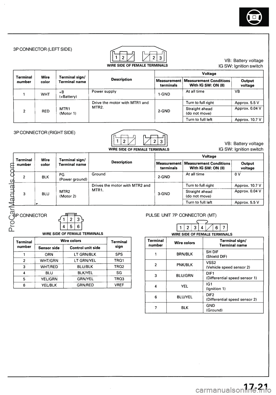
3P CONNECTOR (LEFT SIDE)
VB: Battery voltage
IG SW: Ignition switch
VB: Battery voltage
IG SW: Ignition switch
PULSE UNIT 7P CONNECTOR (MT)
6P CONNECTOR
3P CONNECTOR (RIGHT SIDE)ProCarManuals.com
Page 909 of 1503
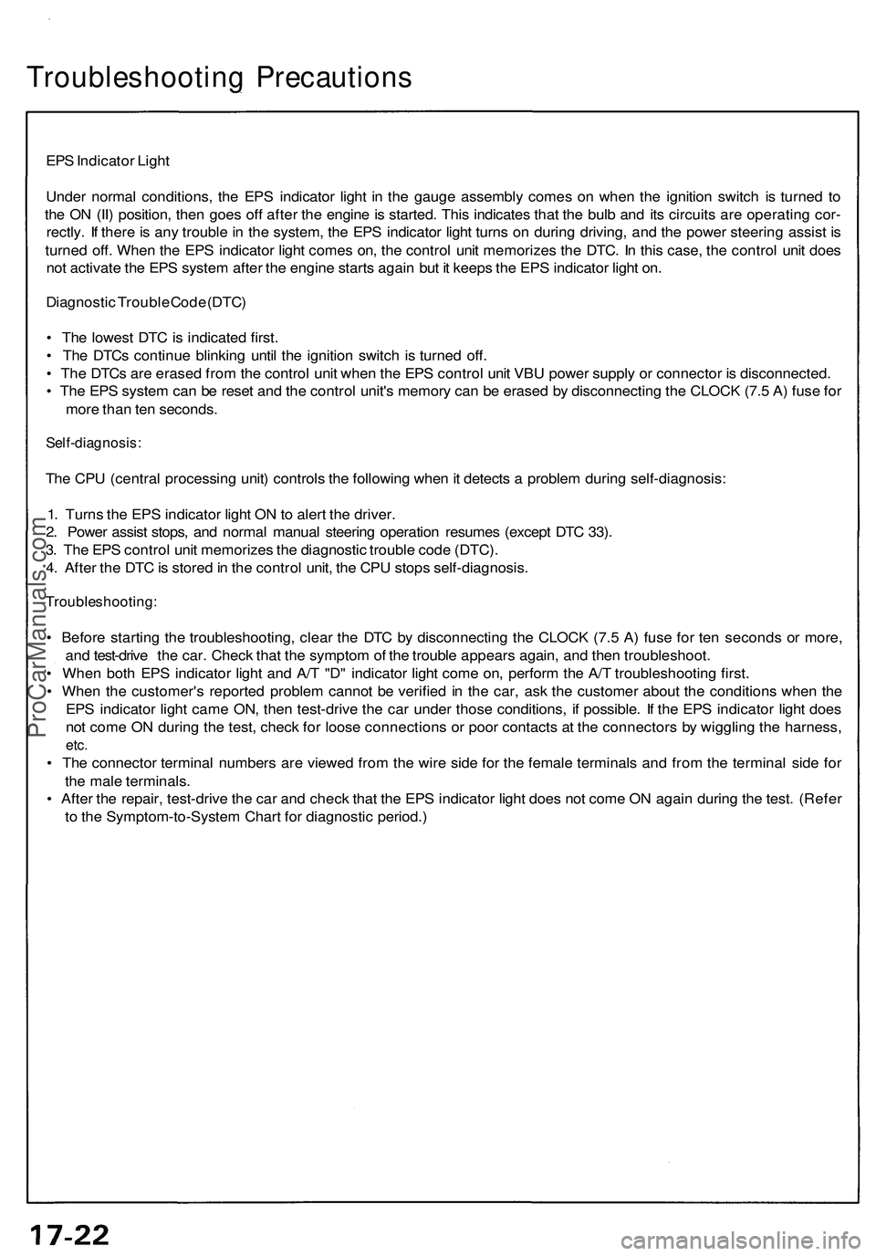
Troubleshooting Precautions
EPS Indicator Light
Under normal conditions, the EPS indicator light in the gauge assembly comes on when the ignition switch is turned to
the ON (II) position, then goes off after the engine is started. This indicates that the bulb and its circuits are operating cor-
rectly. If there is any trouble in the system, the EPS indicator light turns on during driving, and the power steering assist is
turned off. When the EPS indicator light comes on, the control unit memorizes the DTC. In this case, the control unit does
not activate the EPS system after the engine starts again but it keeps the EPS indicator light on.
Diagnostic Trouble Code (DTC)
• The lowest DTC is indicated first.
• The DTCs continue blinking until the ignition switch is turned off.
• The DTCs are erased from the control unit when the EPS control unit VBU power supply or connector is disconnected.
• The EPS system can be reset and the control unit's memory can be erased by disconnecting the CLOCK (7.5 A) fuse for
more than ten seconds.
Self-diagnosis:
The CPU (central processing unit) controls the following when it detects a problem during self-diagnosis:
1. Turns the EPS indicator light ON to alert the driver.
2. Power assist stops, and normal manual steering operation resumes (except DTC 33).
3. The EPS control unit memorizes the diagnostic trouble code (DTC).
4. After the DTC is stored in the control unit, the CPU stops self-diagnosis.
Troubleshooting:
• Before starting the troubleshooting, clear the DTC by disconnecting the CLOCK (7.5 A) fuse for ten seconds or more,
and test-drive the car. Check that the symptom of the trouble appears again, and then troubleshoot.
• When both EPS indicator light and A/T "D" indicator light come on, perform the A/T troubleshooting first.
• When the customer's reported problem cannot be verified in the car, ask the customer about the conditions when the
EPS indicator light came ON, then test-drive the car under those conditions, if possible. If the EPS indicator light does
not come ON during the test, check for loose connections or poor contacts at the connectors by wiggling the harness,
etc.
• The connector terminal numbers are viewed from the wire side for the female terminals and from the terminal side for
the male terminals.
• After the repair, test-drive the car and check that the EPS indicator light does not come ON again during the test. (Refer
to the Symptom-to-System Chart for diagnostic period.)ProCarManuals.com
Page 920 of 1503
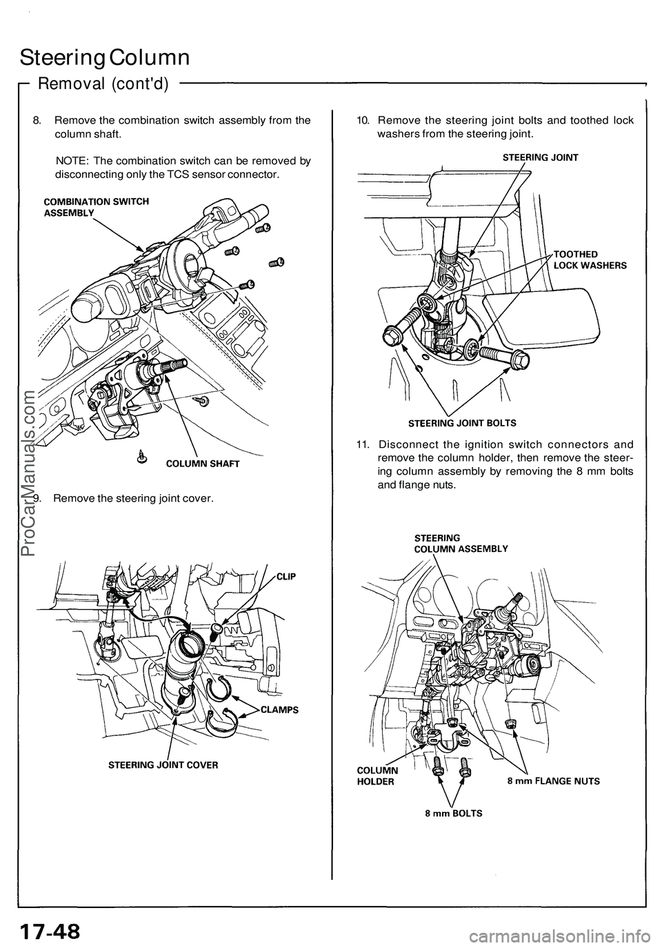
Steering Column
Removal (cont'd)
8. Remove the combination switch assembly from the
column shaft.
NOTE: The combination switch can be removed by
disconnecting only the TCS sensor connector.
10. Remove the steering joint bolts and toothed lock
washers from the steering joint.
9. Remove the steering joint cover.
11. Disconnect the ignition switch connectors and
remove the column holder, then remove the steer-
ing column assembly by removing the 8 mm bolts
and flange nuts.ProCarManuals.com
Page 1014 of 1503
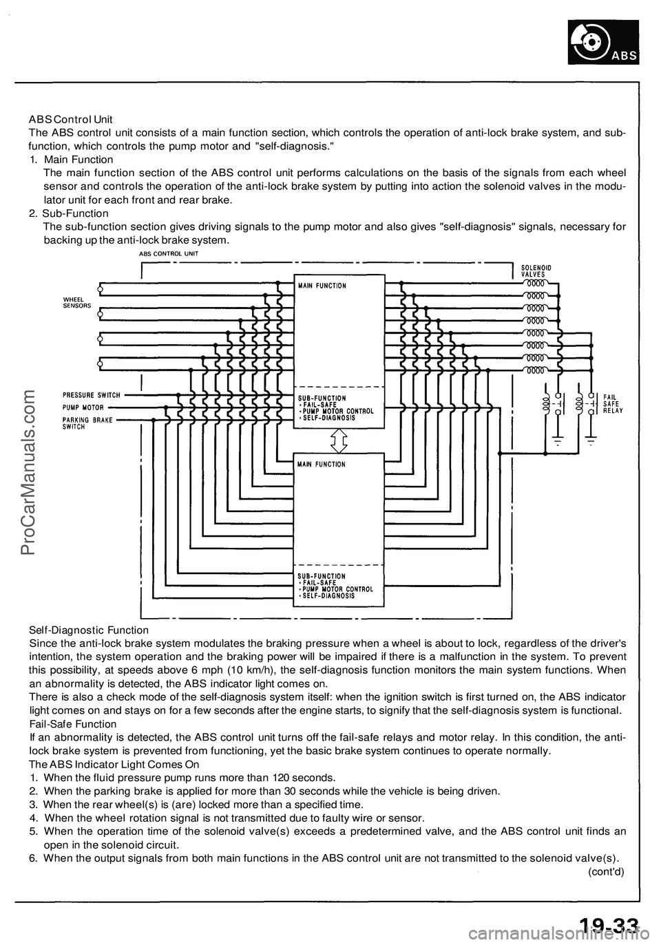
ABS Control Unit
The ABS control unit consists of a main function section, which controls the operation of anti-lock brake system, and sub-
function, which controls the pump motor and "self-diagnosis."
1. Main Function
The main function section of the ABS control unit performs calculations on the basis of the signals from each wheel
sensor and controls the operation of the anti-lock brake system by putting into action the solenoid valves in the modu-
lator unit for each front and rear brake.
2. Sub-Function
The sub-function section gives driving signals to the pump motor and also gives "self-diagnosis" signals, necessary for
backing up the anti-lock brake system.
Self-Diagnostic Function
Since the anti-lock brake system modulates the braking pressure when a wheel is about to lock, regardless of the driver's
intention, the system operation and the braking power will be impaired if there is a malfunction in the system. To prevent
this possibility, at speeds above 6 mph (10 km/h), the self-diagnosis function monitors the main system functions. When
an abnormality is detected, the ABS indicator light comes on.
There is also a check mode of the self-diagnosis system itself: when the ignition switch is first turned on, the ABS indicator
light comes on and stays on for a few seconds after the engine starts, to signify that the self-diagnosis system is functional.
Fail-Safe Function
If an abnormality is detected, the ABS control unit turns off the fail-safe relays and motor relay. In this condition, the anti-
lock brake system is prevented from functioning, yet the basic brake system continues to operate normally.
The ABS Indicator Light Comes On
1. When the fluid pressure pump runs more than 120 seconds.
2. When the parking brake is applied for more than 30 seconds while the vehicle is being driven.
3. When the rear wheel(s) is (are) locked more than a specified time.
4. When the wheel rotation signal is not transmitted due to faulty wire or sensor.
5. When the operation time of the solenoid valve(s) exceeds a predetermined valve, and the ABS control unit finds an
open in the solenoid circuit.
6. When the output signals from both main functions in the ABS control unit are not transmitted to the solenoid valve(s).
(cont'd)ProCarManuals.com