1997 ACURA NSX ignition
[x] Cancel search: ignitionPage 1322 of 1503
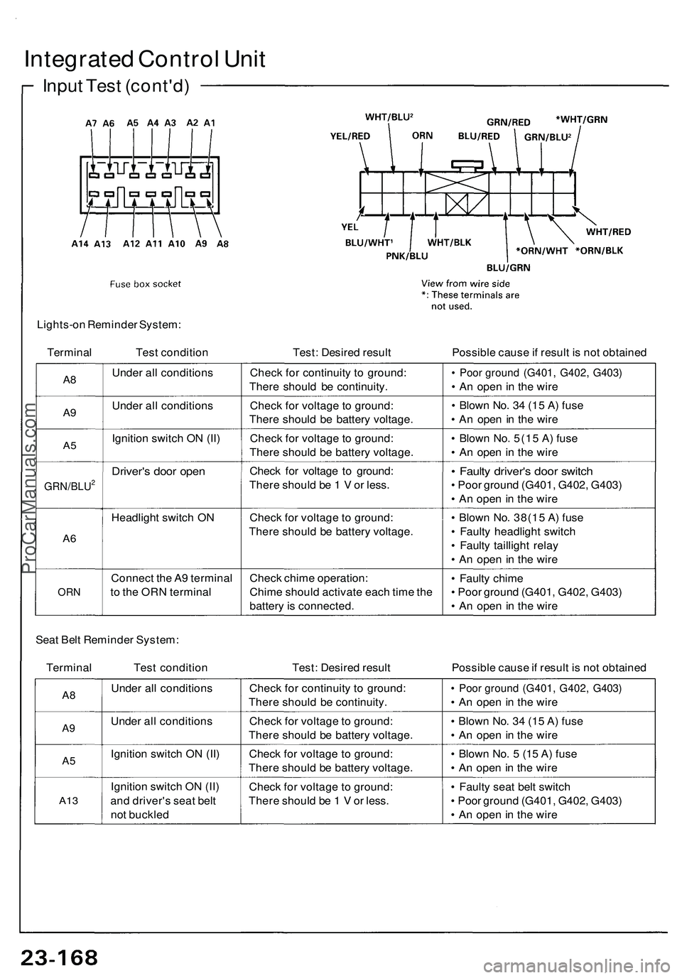
Integrated Control Unit
Input Test (cont'd)
Lights-on Reminder System:
Terminal
Test condition
Test: Desired result
Possible cause if result is not obtained
A8
A9
A5
GRN/BLU2
A6
ORN
Under all conditions
Under all conditions
Ignition switch ON (II)
Driver's door open
Headlight switch ON
Connect the A9 terminal
to the ORN terminal
Check for continuity to ground:
There should be continuity.
Check for voltage to ground:
There should be battery voltage.
Check for voltage to ground:
There should be battery voltage.
Check for voltage to ground:
There should be 1 V or less.
Check for voltage to ground:
There should be battery voltage.
Check chime operation:
Chime should activate each time the
battery is connected.
• Poor ground (G401, G402, G403)
• An open in the wire
• Blown No. 34 (15 A) fuse
• An open in the wire
• Blown No. 5(15 A) fuse
• An open in the wire
• Faulty driver's door switch
• Poor ground (G401, G402, G403)
• An open in the wire
• Blown No. 38(15 A) fuse
• Faulty headlight switch
• Faulty taillight relay
• An open in the wire
• Faulty chime
• Poor ground (G401, G402, G403)
• An open in the wire
Seat Belt Reminder System:
Terminal Test condition
Test: Desired result
Possible cause if result is not obtained
A8
A9
A5
A13
Under all conditions
Under all conditions
Ignition switch ON (II)
Ignition switch ON (II)
and driver's seat belt
not buckled
Check for continuity to ground:
There should be continuity.
Check for voltage to ground:
There should be battery voltage.
Check for voltage to ground:
There should be battery voltage.
Check for voltage to ground:
There should be 1 V or less.
• Poor ground (G401, G402, G403)
• An open in the wire
• Blown No. 34 (15 A) fuse
• An open in the wire
• Blown No. 5 (15 A) fuse
• An open in the wire
• Faulty seat belt switch
• Poor ground (G401, G402, G403)
• An open in the wireProCarManuals.com
Page 1323 of 1503
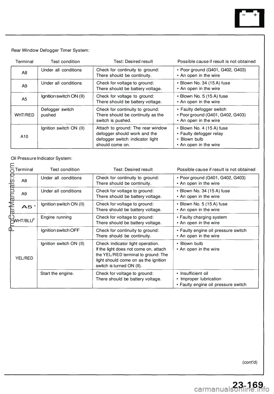
Rear Window Defogger Timer System:
Terminal Test condition
Test: Desired result
Possible cause if result is not obtained
A8
A9
A5
WHT/RED
A10
Under all conditions
Under all conditions
Ignition switch ON (II)
Defogger switch
pushed
Ignition switch ON (II)
Check for continuity to ground:
There should be continuity.
Check for voltage to ground:
There should be battery voltage.
Check for voltage to ground:
There should be battery voltage.
Check for continuity to ground:
There should be continuity as the
switch is pushed.
Attach to ground: The rear window
defogger should work and the
defogger switch indicator light
should come on.
• Poor ground (G401, G402, G403)
• An open in the wire
• Blown No. 34 (15 A) fuse
• An open in the wire
• Blown No. 5 (15 A) fuse
• An open in the wire
• Faulty defogger switch
• Poor ground (G401, G402, G403)
• An open in the wire
• Blown No. 4 (15 A) fuse
• Faulty defogger relay
• Blown bulb
• An open in the wire
Oil Pressure Indicator System:
Terminal Test condition
Test: Desired result
Possible cause if result is not obtained
A8
A9
A5 '
WHT/BLU2
YEL/RED
Under all conditions
Under all conditions
Ignition switch ON (II)
Engine running
Ignition switch OFF
Ignition switch ON (II)
Start the engine.
Check for continuity to ground:
There should be continuity.
Check for voltage to ground:
There should be battery voltage.
Check for voltage to ground:
There should be battery voltage.
Check for voltage to ground:
There should be battery voltage.
Check for continuity to ground:
There should be continuity.
Check indicator light operation.
If the light does not come on, attach
the YEL/RED terminal to ground: The
light should come on as the ignition
switch is turned ON (II).
Check for voltage to ground:
There should be battery voltage.
• Poor ground (G401, G402, G403)
• An open in the wire
• Blown No. 34 (15 A) fuse
• An open in the wire
• Blown No. 5 (15 A) fuse
• An open in the wire
• Faulty charging system
• An open in the wire
• Faulty engine oil pressure switch
• An open in the wire
• Blown bulb
• An open in the wire
• Insufficient oil
• Improper lubrication
• Faulty engine oil pressure switch
(cont'd)ProCarManuals.com
Page 1324 of 1503
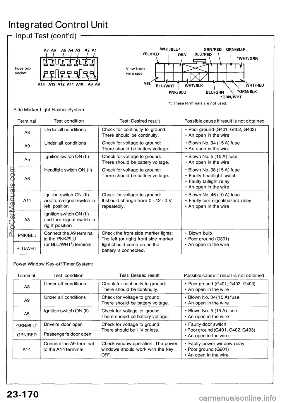
Integrated Contro l Uni t
Inpu t Tes t (cont'd )
Side Marke r Ligh t Flashe r System :
Termina l Tes
t conditio n Test: Desire d resul t Possible caus e if resul t i s no t obtaine d
A8
A9
A 5
A 6
A1 1
A3
PNK/BL U
BLU/WH T
Under al l condition s
Under al l condition s
Ignition switc h O N (II )
Headligh t switc h O N (II )
Ignitio n switc h O N (II )
and tur n signa l switc h in
lef t positio n
Ignition switc h O N (II )
an d tur n signa l switc h i n
righ t positio n
Connec t th e A 9 termina l
t o th e PNK/BL U
(o r BLU/WHT
1) terminal .Chec
k fo r continuit y t o ground :
Ther e shoul d b e continuity .
Chec k fo r voltag e t o ground :
Ther e shoul d b e batter y voltage .
Chec k fo r voltag e to ground :
Ther e shoul d b e batter y voltage .
Chec k fo r voltag e t o ground :
Ther e shoul d b e batter y voltage .
Chec k fo r voltag e t o ground :
It shoul d chang e fro m 0 - 1 2 - 0 V
repeatedly .
Chec k th e fron t sid e marke r lights :
Th e lef t (o r right ) fron t sid e marke r
ligh t shoul d com e o n a s th e
batter y is connected . •
Poo r groun d (G401 , G402 , G403 )
• A n ope n in th e wir e
• Blow n No . 3 4 (1 5 A ) fus e
• A n ope n in th e wir e
• Blow n No . 5 (1 5 A ) fus e
• A n ope n in th e wir e
• Blow n No . 3 8 (1 5 A ) fus e
• Fault y headligh t switc h
• Fault y tailligh t rela y
• A n ope n in th e wir e
• Blow n No . 4 6 (1 0 A ) fus e
• Fault y tur n signal/hazar d rela y
• A n ope n i n th e wir e
• Blow n bul b
• Poo r groun d (G301 )
• A n ope n in th e wir e
Powe r Windo w Key-of f Time r System :
Termina l Tes
t conditio n Test
: Desire d resul t
Possible caus e if resul t i s no t obtaine d
A8
A 9
A 5
GRN/BLU2
GRN/RE D
A14
Unde r al l condition s
Unde r al l condition s
Ignition switc h O N (II )
Driver' s doo r ope n
Passenger' s doo r ope n
Connec t th e A 9 termina l
to th e A1 4 terminal .
Check fo r continuit y t o ground :
Ther e shoul d b e continuity .
Chec k fo r voltag e t o ground :
Ther e shoul d b e batter y voltage .
Chec k fo r voltag e t o ground :
Ther e shoul d b e batter y voltage .
Chec k fo r voltag e t o ground :
Ther e shoul d b e 1 V or less .
Chec k windo w operation : Th e powe r
window s shoul d wor k wit h th e ke y
OFF .
• Poo r groun d (G401 , G402 , G403 )
• A n ope n i n th e wir e
• Blow n No . 34(1 5 A ) fus e
• A n ope n i n th e wir e
• Blow n No . 5 (1 5 A ) fus e
• A n ope n in th e wir e
• Fault y doo r switc h
• Poo r groun d (G401 , G402 , G403 )
• A n ope n in th e wir e
• Fault y powe r windo w rela y
• Poo r groun d (G201 )
• A n ope n in th e wir e
ProCarManuals.com
Page 1325 of 1503
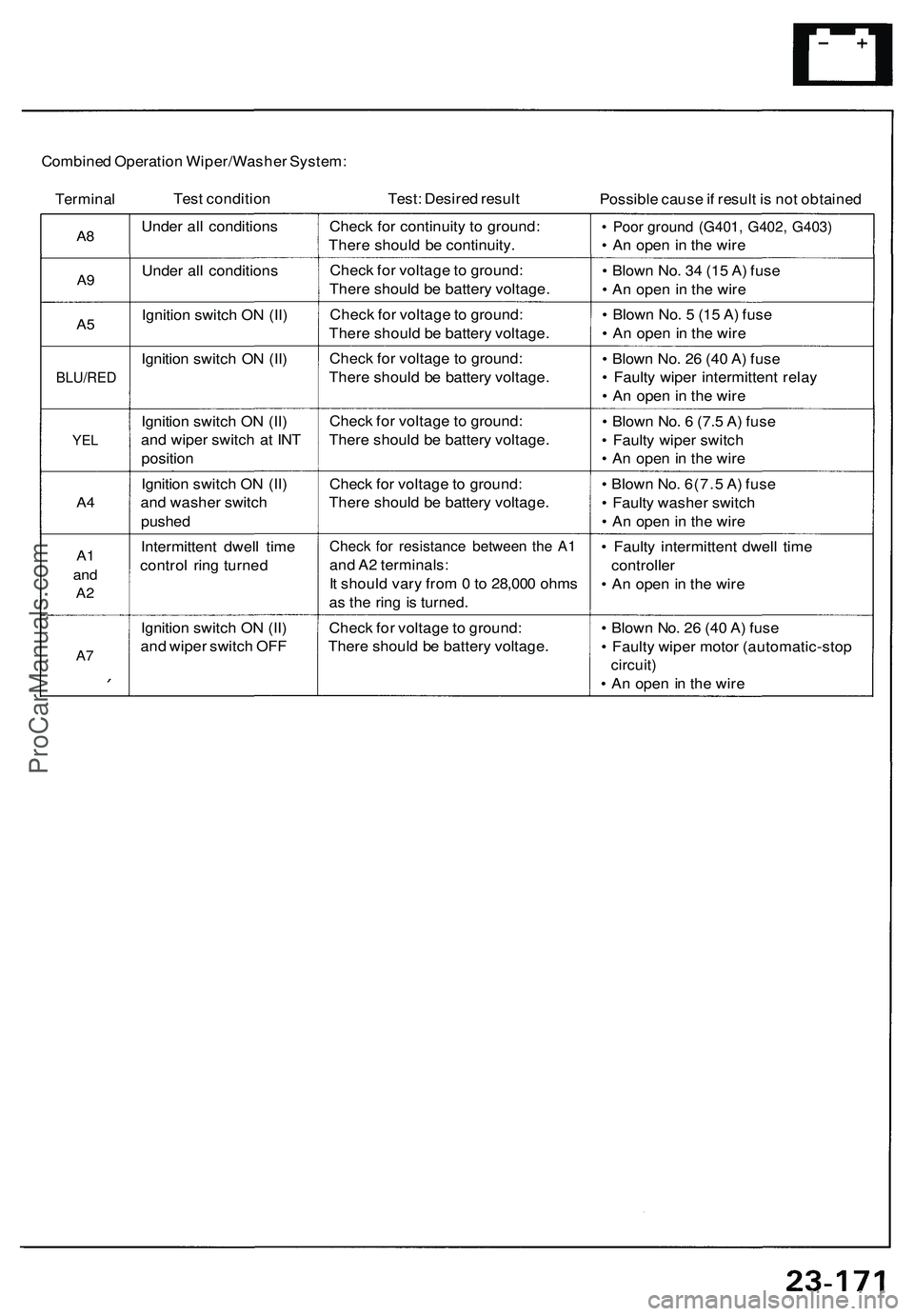
Combined Operation Wiper/Washer System:
Terminal
Test condition
Test: Desired result
Possible cause if result is not obtained
A8
A9
A5
BLU/RED
YEL
A4
A1
and
A2
A7
Under all conditions
Under all conditions
Ignition switch ON (II)
Ignition switch ON (II)
Ignition switch ON (II)
and wiper switch at INT
position
Ignition switch ON (II)
and washer switch
pushed
Intermittent dwell time
control ring turned
Ignition switch ON (II)
and wiper switch OFF
Check for continuity to ground:
There should be continuity.
Check for voltage to ground:
There should be battery voltage.
Check for voltage to ground:
There should be battery voltage.
Check for voltage to ground:
There should be battery voltage.
Check for voltage to ground:
There should be battery voltage.
Check for voltage to ground:
There should be battery voltage.
Check for resistance between the A1
and A2 terminals:
It should vary from 0 to 28,000 ohms
as the ring is turned.
Check for voltage to ground:
There should be battery voltage.
• Poor ground (G401, G402, G403)
• An open in the wire
• Blown No. 34 (15 A) fuse
• An open in the wire
• Blown No. 5 (15 A) fuse
• An open in the wire
• Blown No. 26 (40 A) fuse
• Faulty wiper intermittent relay
• An open in the wire
• Blown No. 6 (7.5 A) fuse
• Faulty wiper switch
• An open in the wire
• Blown No. 6(7.5 A) fuse
• Faulty washer switch
• An open in the wire
• Faulty intermittent dwell time
controller
• An open in the wire
• Blown No. 26 (40 A) fuse
• Faulty wiper motor (automatic-stop
circuit)
• An open in the wireProCarManuals.com
Page 1332 of 1503
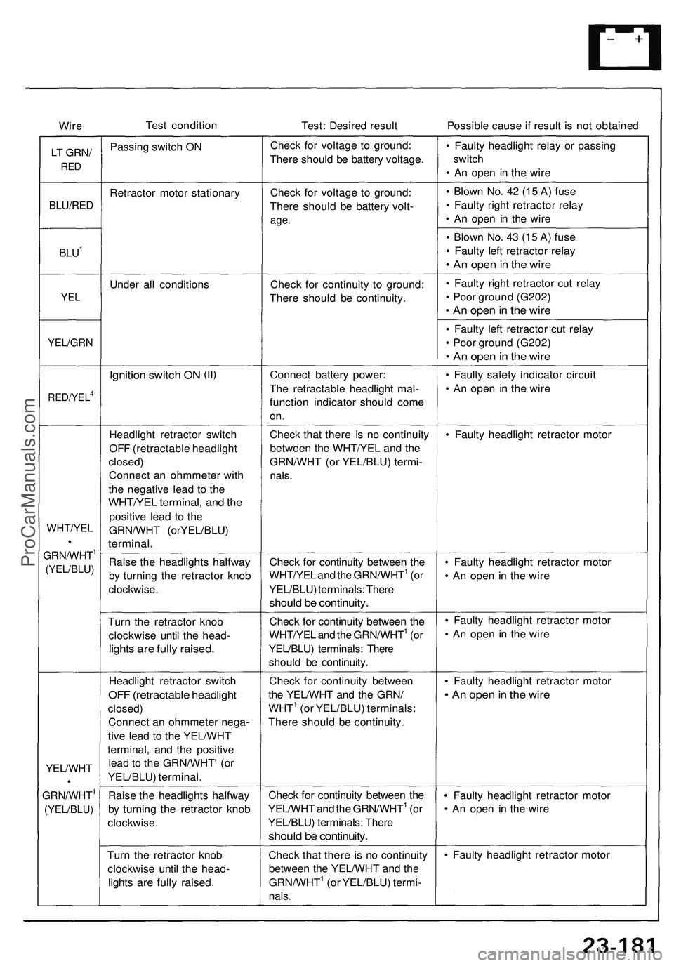
Wire
Test condition
Test: Desired result
Possible cause if result is not obtained
LT
GRN/
RED
Passing switch ON
Check for voltage to ground:
There should be battery voltage.
• Faulty headlight relay or passing
switch
• An open in the wire
BLU/RED
Retractor motor stationary
Check for voltage to ground:
There should be battery volt-
age.
• Blown No. 42 (15 A) fuse
• Faulty right retractor relay
• An open in the wire
BLU1
• Blown No. 43 (15 A) fuse
• Faulty left retractor relay
• An open in the wire
Under all conditions
YEL
Check for continuity to ground:
There should be continuity.
• Faulty right retractor cut relay
• Poor ground (G202)
• An open in the wire
YEL/GRN
• Faulty left retractor cut relay
• Poor ground (G202)
• An open in the wire
Ignition switch ON
RED/YEL4
Connect battery power:
The retractable headlight mal-
function indicator should come
on.
• Faulty safety indicator circuit
• An open in the wire
Headlight retractor switch
OFF (retractable headlight
closed)
Connect an ohmmeter with
the negative lead to the
WHT/YEL terminal, and the
positive lead to the
GRN/WHT (orYEL/BLU)
terminal.
Check that there is no continuity
between the WHT/YEL and the
GRN/WHT (or YEL/BLU) termi-
nals.
• Faulty headlight retractor motor
Raise the headlights halfway
by turning the retractor knob
clockwise.
Check for continuity between the
WHT/YEL and the GRN/WHT1 (or
YEL/BLU) terminals: There
should be continuity.
• Faulty headlight retractor motor
• An open in the wire
Turn the retractor knob
clockwise until the head-
lights are fully raised.
Check for continuity between the
WHT/YEL and the GRN/WHT1 (or
YEL/BLU) terminals: There
should be continuity.
• Faulty headlight retractor motor
• An open in the wire
Headlight retractor switch
OFF (retractable headlight
closed)
Connect an ohmmeter nega-
tive lead to the YEL/WHT
terminal, and the positive
lead to the GRN/WHT' (or
YEL/BLU) terminal.
Check for continuity between
the YEL/WHT and the GRN/
WHT1 (or YEL/BLU) terminals:
There should be continuity.
• Faulty headlight retractor motor
• An open in the wire
Raise the headlights halfway
by turning the retractor knob
clockwise.
Check for continuity between the
YEL/WHT and the GRN/WHT1 (or
YEL/BLU) terminals: There
should be continuity.
• Faulty headlight retractor motor
• An open in the wire
Turn the retractor knob
clockwise until the head-
lights are fully raised.
Check that there is no continuity
between the YEL/WHT and the
GRN/WHT1 (or YEL/BLU) termi-
nals.
• Faulty headlight retractor motor
GRN/WHT1
(YEL/BLU)
WHT/YEL
GRN/WHT1
(YEL/BLU)
YEL/WHTProCarManuals.com
Page 1368 of 1503
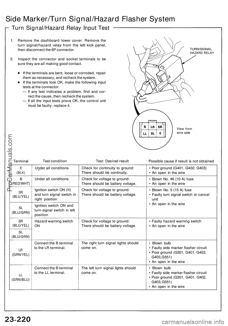
Side Marker/Turn Signal/Hazard Flasher System
Turn Signal/Hazard Relay Input Test
1. Remove the dashboard lower cover. Remove the
turn signal/hazard relay from the left kick panel,
then disconnect the 6P connector.
2. Inspect the connector and socket terminals to be
sure they are all making good contact.
If the terminals are bent, loose or corroded, repair
them as necessary, and recheck the system.
If the terminals look OK, make the following input
tests at the connector.
— If any test indicates a problem, find and cor-
rect the cause, then recheck the system.
— If all the input tests prove OK, the control unit
must be faulty; replace it.
TURN/SIGNAL
HAZARD RELAY
View from
wire side
Terminal
Test condition
Test: Desired result
Possible cause if result is not obtained
E
(BLK)
Under all conditions
Check for continuity to ground:
There should be continuity.
• Poor ground (G401, G402, G403)
• An open in the wire
B
(RED/WHT)
Under all conditions
Check for voltage to ground:
There should be battery voltage.
• Blown No. 46 (10 A) fuse
• An open in the wire
SR
(BLU/YEL)
Ignition switch ON (II)
and turn signal switch in
right position
Check for voltage to ground:
There should be battery voltage.
SL
(BLU/GRN)
Ignition switch ON and
turn signal switch in left
position
• Blown No. 5 (15 A) fuse
• Faulty turn signal switch or cancel
unit
• An open in the wire
SR
(BLU/YEL)
Hazard warning switch
ON
Check for voltage to ground:
There should be battery voltage.
SL
(BLU/GRN)
LR
(GRN/YEL)
Connect the B terminal
to the LR terminal.
The right turn signal lights should
come on.
• Blown bulb
• Faulty side marker flasher circuit
• Poor ground (G301, G401, G402,
G403, G551)
• An open in the wire
LL
(GRN/BLU)
Connect the B terminal
to the LL terminal.
The left turn signal lights should
come on.
• Blown bulb
• Faulty side marker flasher circuit
• Poor ground (G301, G401, G402,
G403, G551)
• An open in the wire
• Faulty hazard warning switch
• An open in the wireProCarManuals.com
Page 1369 of 1503
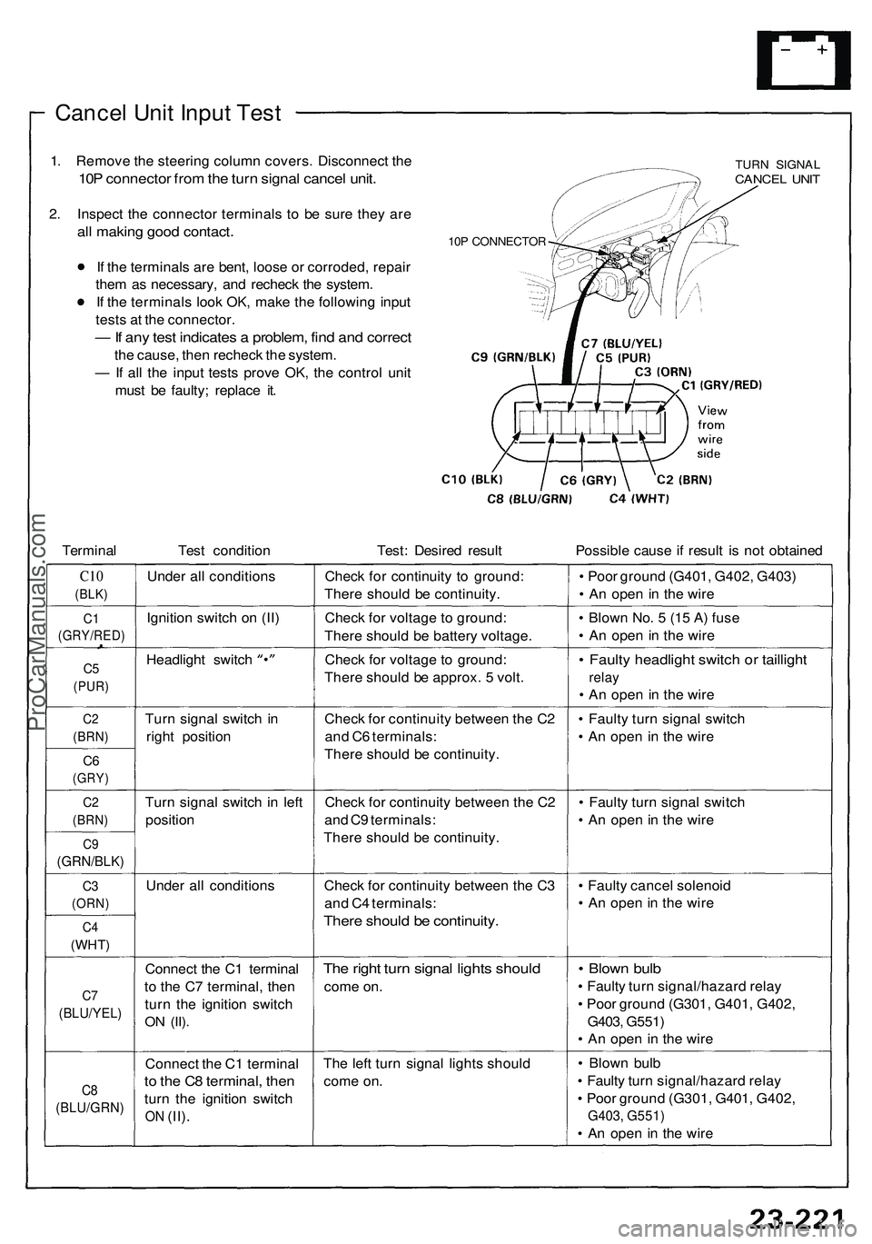
Cancel Unit Input Test
1. Remove the steering column covers. Disconnect the
10P connector from the turn signal cancel unit.
2. Inspect the connector terminals to be sure they are
all making good contact.
If the terminals are bent, loose or corroded, repair
them as necessary, and recheck the system.
If the terminals look OK, make the following input
tests at the connector.
— If any test indicates a problem, find and correct
the cause, then recheck the system.
— If all the input tests prove OK, the control unit
must be faulty; replace it.
10P CONNECTOR
TURN SIGNAL
CANCEL UNIT
Terminal
Test condition
Test: Desired result
Possible cause if result is not obtained
C10
(BLK)
Under all conditions
Check for continuity to ground:
There should be continuity.
• Poor ground (G401, G402, G403)
• An open in the wire
C1
(GRY/RED)
Ignition switch on (II)
Check for voltage to ground:
There should be battery voltage.
• Blown No. 5 (15 A) fuse
• An open in the wire
C5
(PUR)
Headlight switch
Check for voltage to ground:
There should be approx. 5 volt.
• Faulty headlight switch or taillight
relay
• An open in the wire
C2
(BRN)
Turn signal switch in
right position
C6
(GRY)
Check for continuity between the C2
and C6 terminals:
There should be continuity.
• Faulty turn signal switch
• An open in the wire
C2
(BRN)
Turn signal switch in left
position
C9
(GRN/BLK)
Check for continuity between the C2
and C9 terminals:
There should be continuity.
• Faulty turn signal switch
• An open in the wire
C3
(ORN)
Under all conditions
C4
(WHT)
Check for continuity between the C3
and C4 terminals:
There should be continuity.
• Faulty cancel solenoid
• An open in the wire
C7
(BLU/YEL)
Connect the C1 terminal
to the C7 terminal, then
turn the ignition switch
ON
(II).
The right turn signal lights should
come on.
• Blown bulb
• Faulty turn signal/hazard relay
• Poor ground (G301, G401, G402,
G403, G551)
• An open in the wire
C8
(BLU/GRN)
Connect the C1 terminal
to the C8 terminal, then
turn the ignition switch
ON
(II).
The left turn signal lights should
come on.
• Blown bulb
• Faulty turn signal/hazard relay
• Poor ground (G301, G401, G402,
G403, G551)
• An open in the wireProCarManuals.com
Page 1386 of 1503
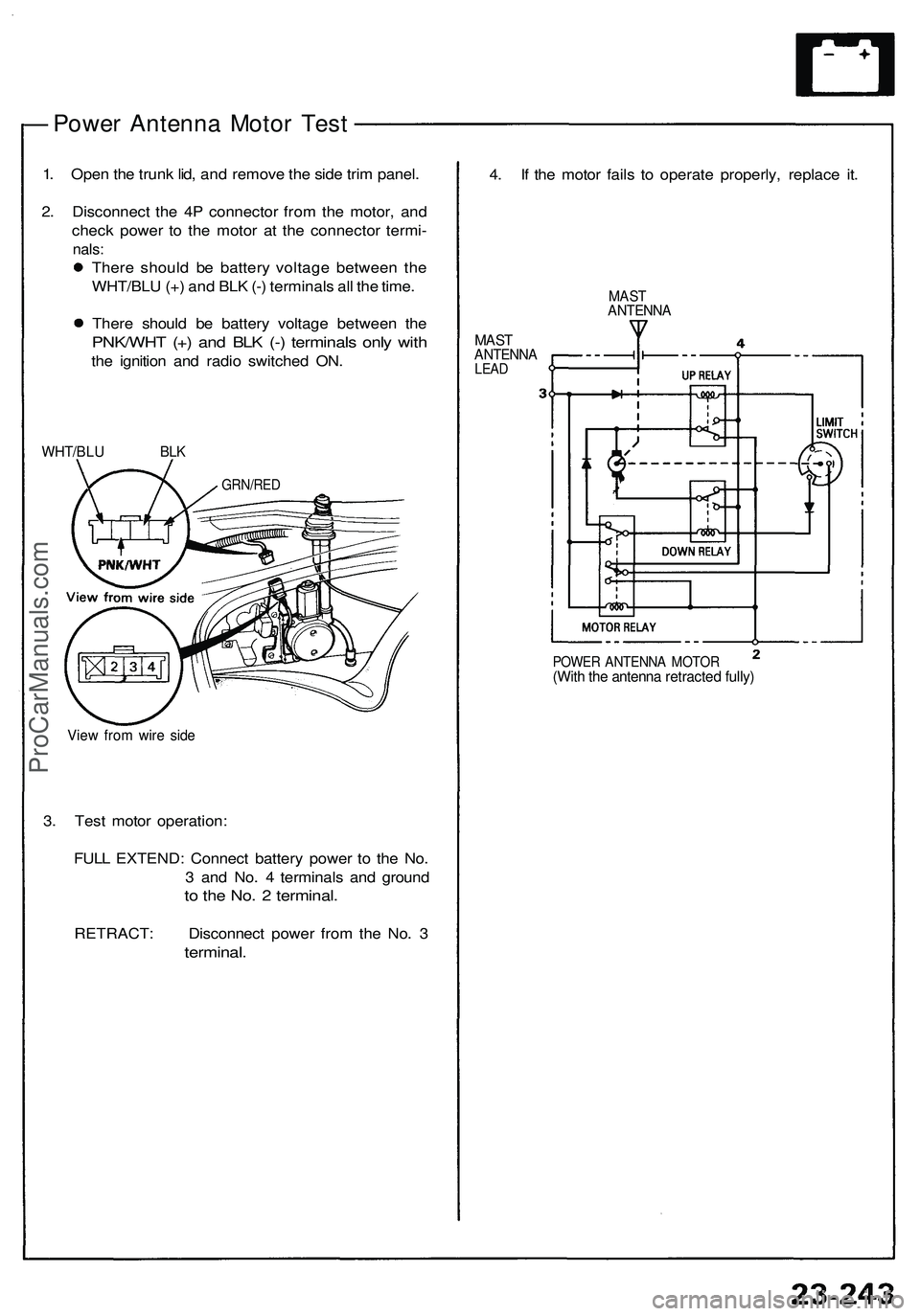
— Power Antenna Motor Test
1. Open the trunk lid, and remove the side trim panel.
2. Disconnect the 4P connector from the motor, and
check power to the motor at the connector termi-
nals:
There should be battery voltage between the
WHT/BLU (+) and BLK (-) terminals all the time.
There should be battery voltage between the
PNK/WHT (+) and BLK (-) terminals only with
the ignition and radio switched ON.
WHT/BLU BLK
View from wire side
3. Test motor operation:
FULL EXTEND: Connect battery power to the No.
3 and No. 4 terminals and ground
to the No. 2 terminal.
RETRACT: Disconnect power from the No. 3
terminal.
4. If the motor fails to operate properly, replace it.
MAST
ANTENNA
MAST
ANTENNA
LEAD
POWER ANTENNA MOTOR
(With the antenna retracted fully)
GRN/REDProCarManuals.com