Page 193 of 1503

Radiator
Engine Coolant Refilling and Bleeding
CAUTION: When pouring engine coolant, be sure to
shut the relay box lid and not let coolant spill on the
electrical parts or the paint. If any coolant spills, rinse it
off immediately.
NOTE:
• Perform this maintenance when the engine is cool.
• Before replacing the coolant, turn the ignition ON,
slowly turn the climate control temperature knob to
90° and turn off the ignition. This will allow the
coolant in the heater to drain out with the rest of the
system.
1. Open the hood, the rear window and the engine
cover.
2. Remove the cover protecting the water pipes and
shift cables on the underside of the car.
3. Before removing the expansion tank cap, first
loosen the cap to lower pressure.
CAUTION: Do not remove the expansion tank cap
when engine is hot. The coolant is under pressure
and may blow out and scald you. Open the cap
slowly when the engine is cool.
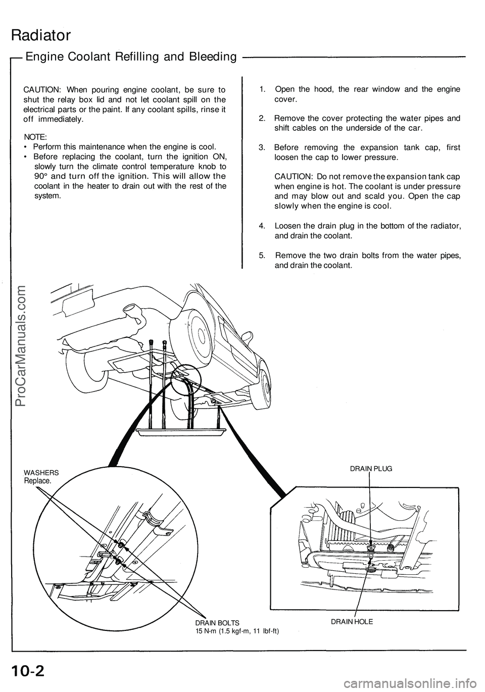
4. Loosen the drain plug in the bottom of the radiator,
and drain the coolant.
5. Remove the two drain bolts from the water pipes,
and drain the coolant.
DRAIN BOLTS
15 N-m (1.5 kgf-m, 11 Ibf-ft)
DRAIN HOLE
DRAIN PLUG
WASHERS
Replace.ProCarManuals.com
Page 521 of 1503

Engine Coolant Refilling and Bleeding
CAUTION: When pouring engine coolant, be sure to
shut the relay box lid and not let coolant spill on the
electrical parts or the paint. If any coolant spills, rinse it
off immediately.
NOTE:
• Perform this maintenance when the engine is cool.
• Before replacing the coolant, turn the ignition ON,
slowly turn the climate control temperature knob to
90° and turn off the ignition. This will allow the
coolant in the heater to drain out with the rest of the
system.
1. Open the hood, the rear window and the engine
cover.
2. Remove the cover protecting the water pipes and
shift cables on the underside of the car.
3. Before removing the expansion tank cap, first
loosen the cap to lower pressure.
CAUTION: Do not remove the expansion tank cap
when engine is hot. The coolant is under pressure
and may blow out and scald you. Open the cap
slowly when the engine is cool.
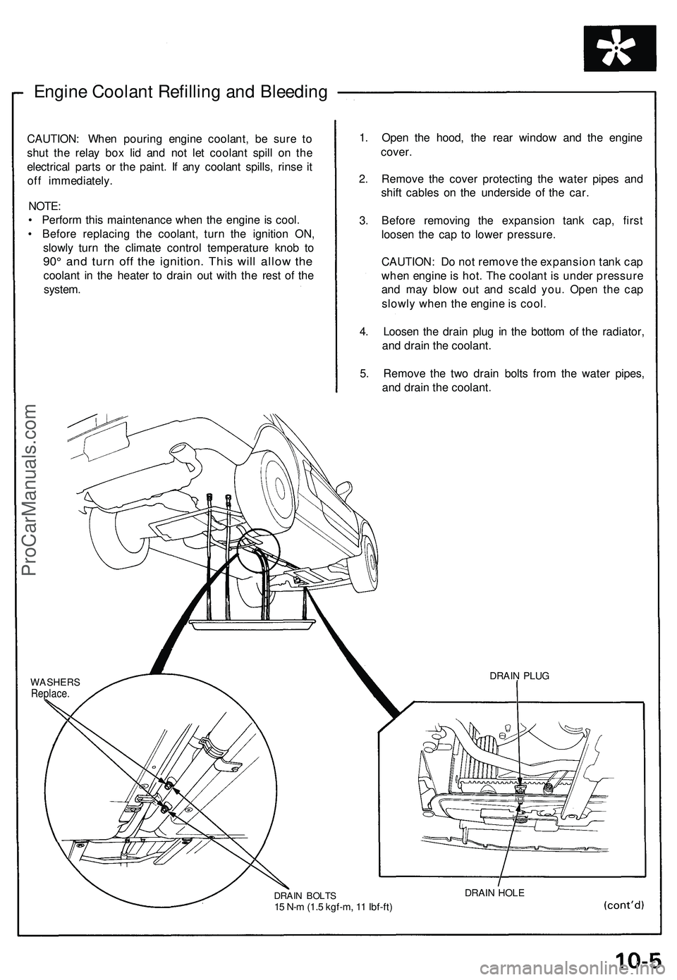
4. Loosen the drain plug in the bottom of the radiator,
and drain the coolant.
5. Remove the two drain bolts from the water pipes,
and drain the coolant.
WASHERS
Replace.
DRAIN BOLTS
15 N-m (1.5 kgf-m, 11 Ibf-ft)
DRAIN HOLE
DRAIN PLUGProCarManuals.com
Page 1112 of 1503
Climate control unit, stereo cassette/radio and glove box removal:
Disassemble in numbered sequence.
NOTE: Remove the center console panel.
CLIMATE CONTROL
UNIT
Disconnect the connectors.
SRS UNIT
Passenger's:
STEREO
CASSETTE RADIO
Disconnect the connectors.
GROUND CABLE
GLOVE BOX
Disconnect the connectors.
TRUNK LID OPENER
MAIN SWITCH
PASSENGER'S
AIRBAG
DLC
CONNECTOR
GLOVE BOX
LID
DASHBOARD LOWER
COVER (Passenger's)
Installation is the reverse of the removal procedure.
NOTE: Make sure the connectors are connected properly.
(cont'd)ProCarManuals.com
Page 1187 of 1503
Function Selection and Operation Check
This check will quickly and automatically select and operate all functions of the climate control system, in the combina-
tions and sequence shown below. It may help clarify a problem, or identify one that didn't show up when you perform
the self-diagnosis circuit check.
Turn the FAN switch to AUTO, then push in both the MODE and AUTO buttons and hold them in while you start the
engine. The control unit will then automatically run the check in eight steps, one step every five seconds.
To stop at one of those steps, push the MODE button; to continue, push it again for each step after that.
Pushing the OFF button or turning the ignition OFF, will turn off the check.
Check the temperature, volume, and source of the air flow, and compare it to what the chart shows it should be.ProCarManuals.com
Page 1189 of 1503
Climate Control Unit Input/Output Signals
CLIMATE
CONTROL UNIT
View from wire sideProCarManuals.com
Page 1191 of 1503
5. Remove the three screws and center console
panel, then disconnect the 3P connector and 4P
connector from the floor wire harness.
CENTER CONSOLE PANEL
6. Remove the four screws, then disconnect the 14P
and 30P connectors from the automatic climate
control unit and remove it.
CLIMATE
CONTROL UNIT
UP CONNECTOR
30P CONNECTOR
7. Install in the reverse order removal.ProCarManuals.com
Page 1195 of 1503

Mode Control Motor
Test
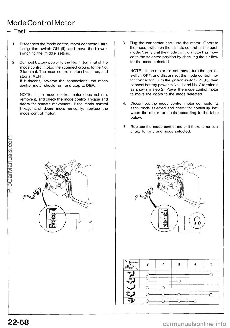
1. Disconnect the mode control motor connector, turn
the ignition switch ON (II), and move the blower
switch to the middle setting.
2. Connect battery power to the No. 1 terminal of the
mode control motor, then connect ground to the No.
2 terminal. The mode control motor should run, and
stop at VENT.
If it doesn't, reverse the connections; the mode
control motor should run, and stop at DEF.
NOTE: If the mode control motor does not run,
remove it, and check the mode control linkage and
doors for smooth movement. If the mode control
linkage and doors move smoothly, replace the
mode control motor.
3. Plug the connector back into the motor. Operate
the mode switch on the climate control unit to each
mode. Verify that the mode control motor has mov-
ed to the selected position by checking the air flow
for the mode selected.
NOTE: If the motor did not move, turn the ignition
switch OFF, and disconnect the mode control mo-
tor connector. Turn the ignition switch ON (II), then
connect battery power to No. 1 and No. 2 terminals
as shown in step 2. Power the mode control motor
to move the doors to the mode selected.
4. Disconnect the mode control motor connector at
each mode selected and check for continuity bet-
ween the motor terminals according to the table
below.
5. Replace the mode control motor if there is no con-
tinuity for any one mode selected.ProCarManuals.com
Page 1235 of 1503
Relay and Control Unit Locations
Dashboard
IMMOBILIZER CONTROL UNIT
CLIMATE CONTROL UNIT
TURN SIGNAL/HAZARD
RELAY
DASHBOARD
LOWER COVER
INTEGRATED
CONTROL UNIT
UNDER-DASH FUSE BOXProCarManuals.com