Page 269 of 1503
Lighting Syste m
HID Bulb Removal
1. Mak e sur e yo u hav e th e anti-thef t cod e fo r th e radio ,
the n writ e dow n th e frequencie s fo r th e radio' s prese t
buttons .
2 . Tur n th e combinatio n ligh t switc h OFF .
3 . Disconnec t th e batter y negativ e cable , the n
disconnec t th e positiv e cable .
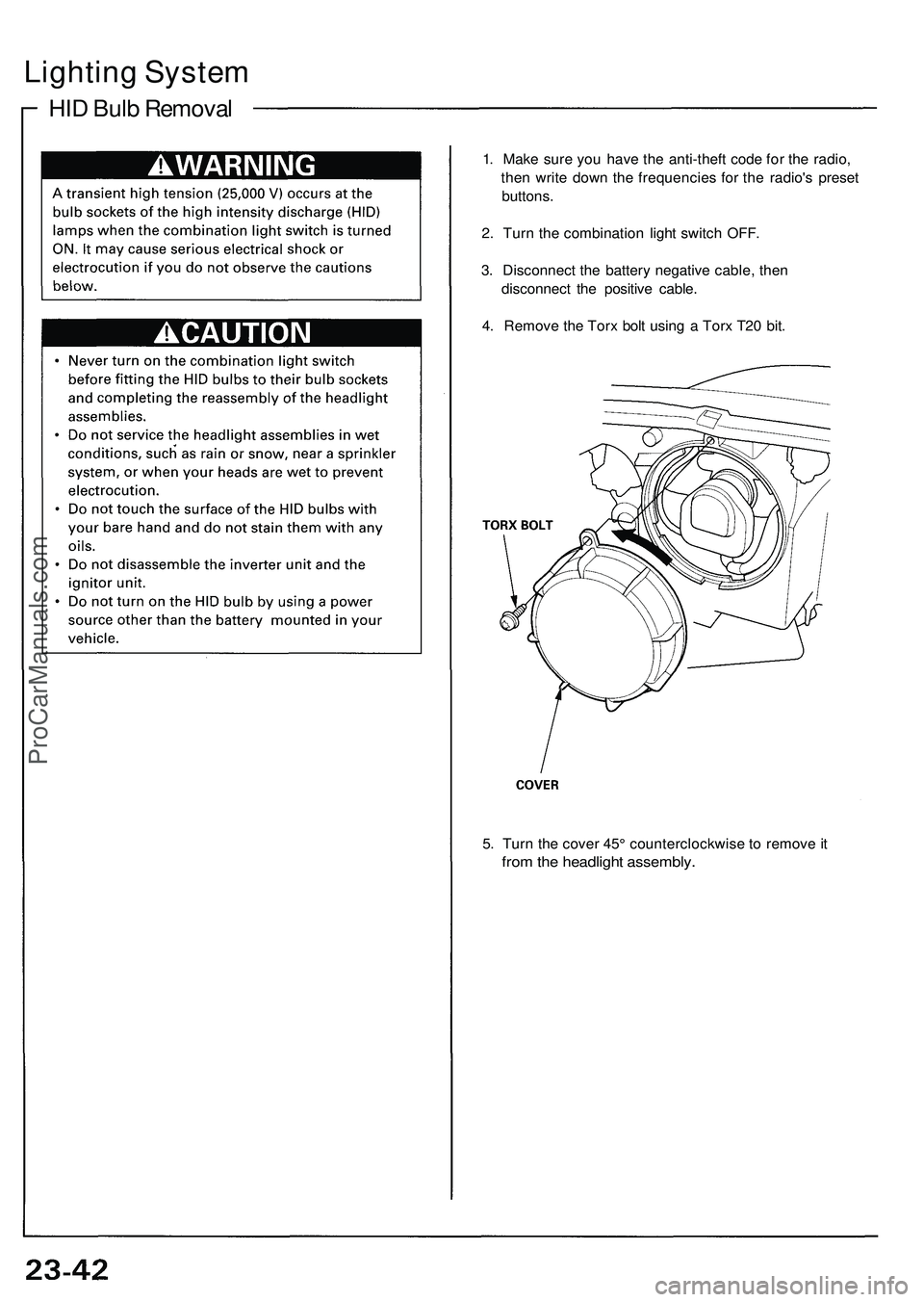
4 . Remov e th e Tor x bol t usin g a Tor x T2 0 bit .
5 . Tur n th e cove r 45 ° counterclockwis e to remov e it
fro m th e headligh t assembly .
ProCarManuals.com
Page 359 of 1503
Transmitter Test
NOTE:
• If the doors unlock or lock with the transmitter, but
the LED on the transmitter does not come on, the
LED is faulty; replace the transmitter.
• If any door is open, you cannot lock the door with the
transmitter.
• If you unlocked the doors with the transmitter, but do
not open any of the doors within 30 seconds, the
doors relock automatically.
• The doors do not lock or unlock with the transmitter
if the ignition key is inserted in the ignition switch.
1. Press the lock or unlock button five or six times to
reset the transmitter.
• If the locks work, the transmitter is OK.
• If the locks don't work, go to step 2.
2. Open the transmitter and recheck for water damage.
• If you find any water damage, replace the transmit-
ter.
• If there is no water damage, go to step 3.
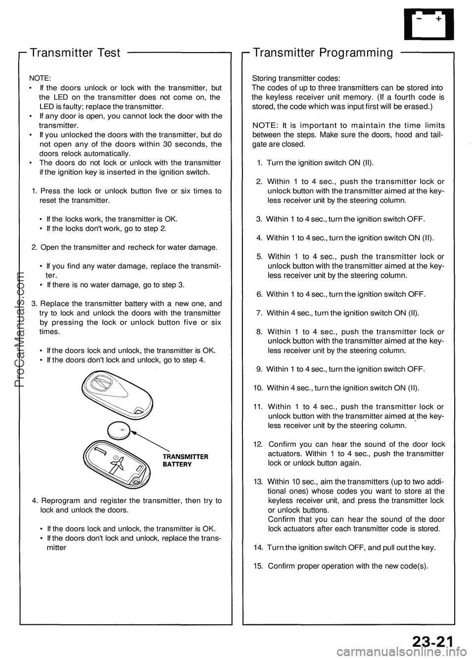
3. Replace the transmitter battery with a new one, and
try to lock and unlock the doors with the transmitter
by pressing the lock or unlock button five or six
times.
• If the doors lock and unlock, the transmitter is OK.
• If the doors don't lock and unlock, go to step 4.
4. Reprogram and register the transmitter, then try to
lock and unlock the doors.
• If the doors lock and unlock, the transmitter is OK.
• If the doors don't lock and unlock, replace the trans-
mitter
Transmitter Programming
Storing transmitter codes:
The codes of up to three transmitters can be stored into
the keyless receiver unit memory. (If a fourth code is
stored, the code which was input first will be erased.)
NOTE: It is important to maintain the time limits
between the steps. Make sure the doors, hood and tail-
gate are closed.
1. Turn the ignition switch ON (II).
2. Within 1 to 4 sec., push the transmitter lock or
unlock button with the transmitter aimed at the key-
less receiver unit by the steering column.
3. Within 1 to 4 sec., turn the ignition switch OFF.
4. Within 1 to 4 sec., turn the ignition switch ON (II).
5. Within 1 to 4 sec., push the transmitter lock or
unlock button with the transmitter aimed at the key-
less receiver unit by the steering column.
6. Within 1 to 4 sec., turn the ignition switch OFF.
7. Within 4 sec., turn the ignition switch ON (II).
8. Within 1 to 4 sec., push the transmitter lock or
unlock button with the transmitter aimed at the key-
less receiver unit by the steering column.
9. Within 1 to 4 sec., turn the ignition switch OFF.
10. Within 4 sec., turn the ignition switch ON (II).
11. Within 1 to 4 sec., push the transmitter lock or
unlock button with the transmitter aimed at the key-
less receiver unit by the steering column.
12. Confirm you can hear the sound of the door lock
actuators. Within 1 to 4 sec., push the transmitter
lock or unlock button again.
13. Within 10 sec., aim the transmitters (up to two addi-
tional ones) whose codes you want to store at the
keyless receiver unit, and press the transmitter lock
or unlock buttons.
Confirm that you can hear the sound of the door
lock actuators after each transmitter code is stored.
14. Turn the ignition switch OFF, and pull out the key.
15. Confirm proper operation with the new code(s).ProCarManuals.com
Page 918 of 1503
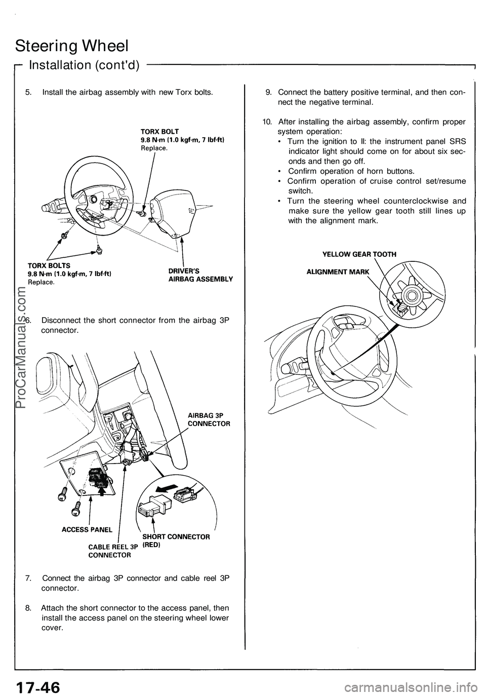
7. Connec t th e airba g 3 P connecto r an d cabl e ree l 3 P
connector .
8. Attac h th e shor t connecto r t o th e acces s panel , the n
instal l th e acces s pane l o n th e steerin g whee l lowe r
cover .
Steerin g Whee l
Installatio n (cont'd )
5. Instal l th e airba g assembl y wit h ne w Tor x bolts .
6 . Disconnec t th e shor t connecto r fro m th e airba g 3 P
connector . 9
. Connec t th e batter y positiv e terminal , an d the n con -
nec t th e negativ e terminal .
10 . Afte r installin g th e airba g assembly , confir m prope r
syste m operation :
• Tur n th e ignitio n t o II : th e instrumen t pane l SR S
indicato r ligh t shoul d com e o n fo r abou t si x sec -
ond s an d the n g o off .
• Confir m operation of hor n buttons .
• Confir m operatio n o f cruis e contro l set/resum e
switch .
• Tur n th e steerin g whee l counterclockwis e an d
mak e sur e th e yello w gea r toot h stil l line s u p
wit h th e alignmen t mark .
ProCarManuals.com
Page 1187 of 1503
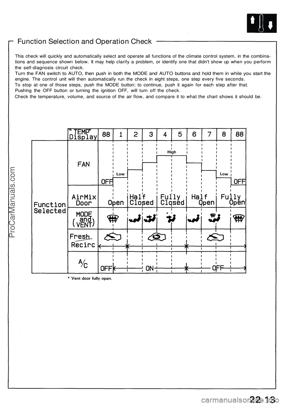
Function Selection and Operation Check
This check will quickly and automatically select and operate all functions of the climate control system, in the combina-
tions and sequence shown below. It may help clarify a problem, or identify one that didn't show up when you perform
the self-diagnosis circuit check.
Turn the FAN switch to AUTO, then push in both the MODE and AUTO buttons and hold them in while you start the
engine. The control unit will then automatically run the check in eight steps, one step every five seconds.
To stop at one of those steps, push the MODE button; to continue, push it again for each step after that.
Pushing the OFF button or turning the ignition OFF, will turn off the check.
Check the temperature, volume, and source of the air flow, and compare it to what the chart shows it should be.ProCarManuals.com
Page 1487 of 1503
Supplemental Restrain t Syste m (SRS )
Airbag Assembl y Installatio n
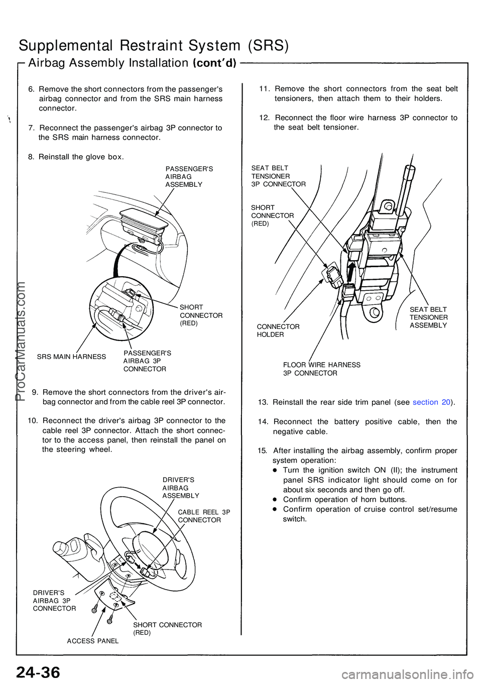
6. Remov e th e shor t connector s fro m th e passenger' s
airba g connecto r an d fro m th e SR S mai n harnes s
connector .
7 . Reconnec t th e passenger' s airba g 3 P connecto r t o
th e SR S mai n harnes s connector .
8 . Reinstal l th e glov e box .
PASSENGER' SAIRBAGASSEMBL Y
SHORTCONNECTO R(RED)
SRS MAI N HARNES SPASSENGER' SAIRBAG 3 PCONNECTO R
9. Remov e th e shor t connector s fro m th e driver' s air -
ba g connecto r an d fro m th e cabl e ree l 3 P connector .
10 . Reconnec t th e driver' s airba g 3 P connecto r t o th e
cabl e ree l 3 P connector . Attac h th e shor t connec -
to r t o th e acces s panel , the n reinstal l th e pane l o n
th e steerin g wheel .
DRIVER' SAIRBAGASSEMBL Y
CABLE REE L 3 PCONNECTO R
11. Remov e th e shor t connector s fro m th e sea t bel t
tensioners , the n attac h the m to thei r holders .
12 . Reconnec t th e floo r wir e harnes s 3 P connecto r t o
th e sea t bel t tensioner .
SEAT BEL TTENSIONE R3P CONNECTO R
SHORTCONNECTO R(RED)
DRIVER' SAIRBAG 3 PCONNECTO R
SHORT CONNECTO R(RED)ACCES S PANE L
CONNECTO RHOLDER
SEAT BEL TTENSIONE RASSEMBLY
FLOOR WIR E HARNES S3P CONNECTO R
13. Reinstal l th e rea r sid e tri m pane l (se e sectio n 20 ).
14. Reconnec t th e batter y positiv e cable , the n th e
negativ e cable .
15 . Afte r installin g th e airba g assembly , confir m prope r
syste m operation :
Tur n th e ignitio n switc h O N (II) ; th e instrumen t
pane l SR S indicato r ligh t shoul d com e o n fo r
abou t si x second s an d the n g o off .
Confir m operatio n o f hor n buttons .
Confir m operatio n of cruis e contro l set/resum e
switch .
ProCarManuals.com
Page 1497 of 1503
Supplemental Restrain t Syste m (SRS )
Cable Ree l Installatio n
17. Reconnec t th e batter y positiv e cable , the n th e
negativ e cable .
18 . Afte r installin g th e cabl e reel , confir m prope r
syste m operation :
Tur n th e ignitio n switc h O N (II) ; th e instrumen t
pane l SR S indicato r ligh t shoul d com e o n fo r
abou t si x second s an d the n g o off .
Confir m operatio n o f hor n buttons .
Confir m operatio n o f th e headligh t an d wipe r
switches .
Confir m operatio n o f cruis e contro l set/resum e
switch .
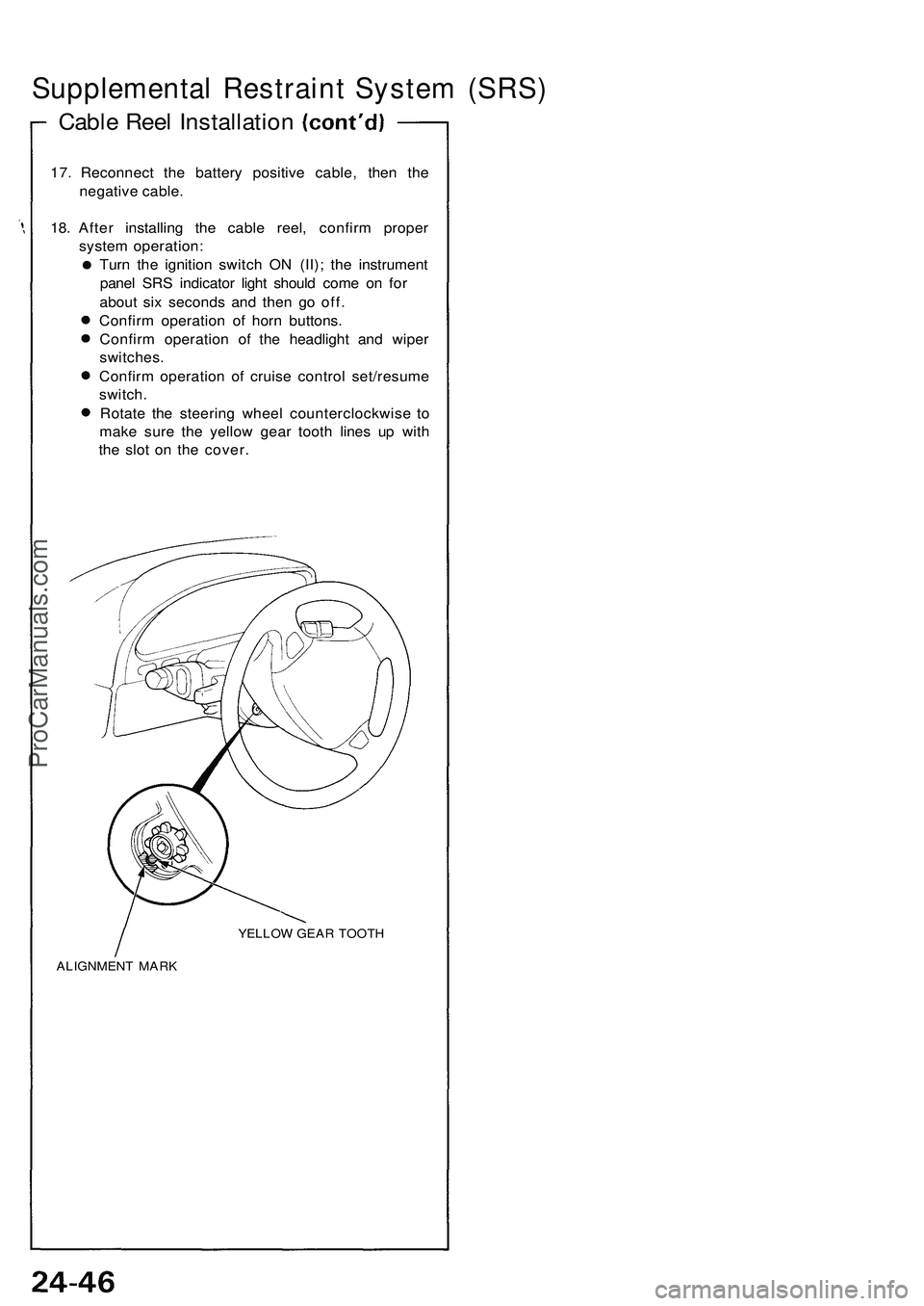
Rotat e th e steerin g whee l counterclockwis e t o
mak e sur e th e yello w gea r toot h line s u p wit h
th e slo t o n th e cover .
YELLO W GEA R TOOT H
ALIGNMEN T MAR K
ProCarManuals.com