Page 1263 of 1503
Ignition Syste m
Idle Spee d Inspectio n
1. Star t th e engine . Hol d th e engin e a t 3,00 0 rp m wit h
no loa d (A/ T i n o r position , M/ T i n neutral )
unti l th e radiato r fa n come s on , the n le t i t idle .
2 . Connec t a tachomete r t o th e tes t tachomete r con -
nector .
TEST
TACHOMETE R
CONNECTO R
3. Chec k th e idl e spee d wit h al l electrica l system s
turne d OFF .
Idl e Spee d (rpm) :
4 . Adjus t th e idl e spee d if necessar y (se e sectio n 11 ).
Ignitio n Contro l Modul e (ICM )
Replacemen t
1. Disconnec t th e 8 P an d 6 P connector s fro m th e igni -
tio n contro l modul e (ICM) .
2. Remov e th e tw o mountin g bolts , an d slid e th e IC M
out towar d th e fron t side . B e carefu l no t t o damag e
th e vacuu m hose s whe n removin g th e ICM .
MOUNTIN G BOLT S12 N- m(1.2 kgf-m , 9 Ibf-ft )
6P CONNECTO R
8P CONNECTO R
G103
SERVIC E LOO P
JUMP STAR TTERMINA L
TESTTACHOMETE RCONNECTOR
ProCarManuals.com
Page 1264 of 1503

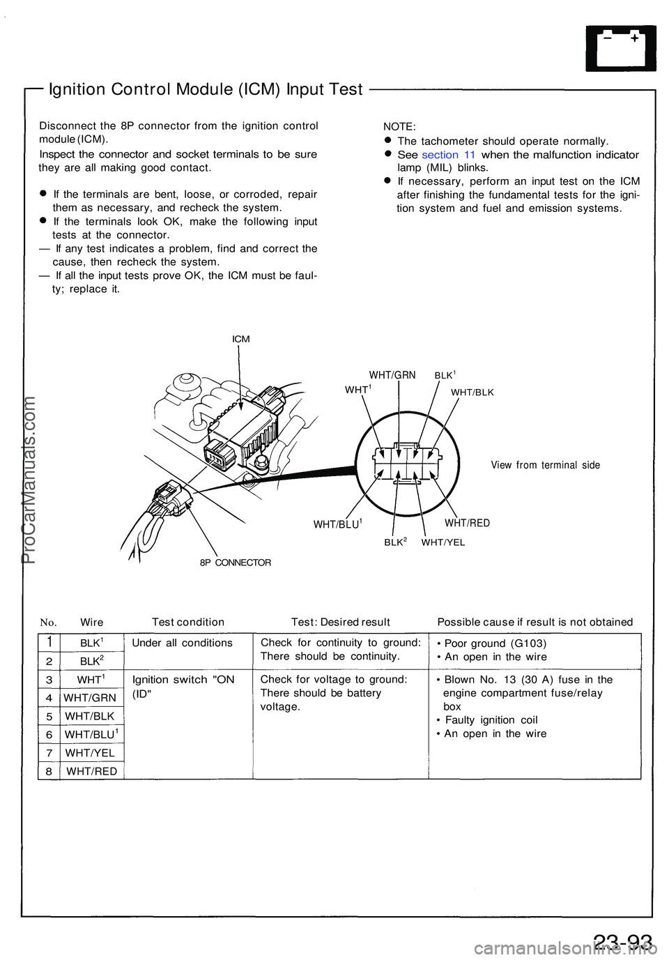
Ignition Contro l Modul e (ICM ) Inpu t Tes t
Disconnec t th e 8 P connecto r fro m th e ignitio n contro l
modul e (ICM) .
Inspec t th e connecto r an d socke t terminal s t o b e sur e
they ar e al l makin g goo d contact .
I f th e terminal s ar e bent , loose , o r corroded , repai r
them as necessary , an d rechec k th e system .
I f th e terminal s loo k OK , mak e th e followin g inpu t
test s a t th e connector .
— If an y tes t indicate s a problem , fin d an d correc t th e
cause , the n rechec k th e system .
— If al l th e inpu t test s prov e OK , th e IC M mus t b e faul -
ty ; replac e it .
IC M
NOTE :
The tachomete r shoul d operat e normally .
See sectio n 1 1 whe n th e malfunctio n indicato r
lamp (MIL ) blinks .
I f necessary , perfor m a n inpu t tes t o n th e IC M
afte r finishin g th e fundamenta l test s fo r th e igni -
tio n syste m an d fue l an d emissio n systems .
WHT/GRN
WHT1BLK1
WHT/BLK
View fro m termina l sid e
WHT/RE D
BLK2 WHT/YE L
8P CONNECTO R
No.Wir eTes t conditio n Test: Desire d resul t Possible caus e if resul t i s no t obtaine d
1
2
3
4
5
6
7
8
BLK1
BLK2
WHT1
WHT/GR N
WHT/BLK
WHT/BLU1
WHT/YE L
WHT/RE D
Under al l condition s
Ignition switc h "O N
(ID"
Chec k fo r continuit y t o ground :
Ther e shoul d b e continuity .
Chec k fo r voltag e t o ground :
Ther e shoul d b e batter y
voltage . •
Poo r groun d (G103 )
• A n ope n i n th e wir e
• Blow n No . 1 3 (3 0 A ) fus e i n th e
engin e compartmen t fuse/rela y
box
• Fault y ignitio n coi l
• A n ope n i n th e wir e
23-9 3
WHT/BLU1
ProCarManuals.com
Page 1265 of 1503
Ignition System
Ignition Coils/Spark Plugs Removal
CAUTION:
Ignition coils and spark plugs can become very hot in
use; do not touch them until the engine has cooled
down.
1. Remove the ignition coil covers.
2. Disconnect the 3P connectors from the ignition
coils.
3. Remove the ignition coils.
4. Remove the spark plugs.
NOTE: Different ignition coils and ignition coil
covers are used for the front and rear cylinders. Be
sure to use the correct ones when mounting them.
IGNITION COIL COVER
RUBBER
SEAL
PLATINUM TIP SPARK PLUG
CYLINDER HEAD
COVER
3P CONNECTOR
IGNITION COILProCarManuals.com
Page 1266 of 1503
Ignition Coi l Tes t
1. Wit h th e ignitio n switc h OFF , remov e th e ignitio n
coil.
2. Usin g a n ohmmeter , measur e resistanc e betwee n
th e terminals . Replac e th e coi l i f th e resistanc e i s
no t withi n specifications .
NOTE: Resistanc e wil l var y wit h th e coi l
temperature ; specificatio n i s a t 77° F (25°C) .
Primary Windin g Resistanc e
(Betwee n th e A an d B terminals) : 0.9 - 1. 1 ohm s
3. I f primar y windin g resistanc e i s OK , substitut e aknown-goo d ignitio n coil , an d chec k th e syste m
operation .
If th e syste m is normal , replac e th e origina l ignitio n
coil.
A TERMINA L
B TERMINA LIGNITIONCOIL
SECONDAR Y
WINDINGTERMINA L
SPARK PLU G
VOLTAG E
SENSO R
SECONDAR Y
WINDINGTERMINA L
ProCarManuals.com
Page 1267 of 1503

Ignition System
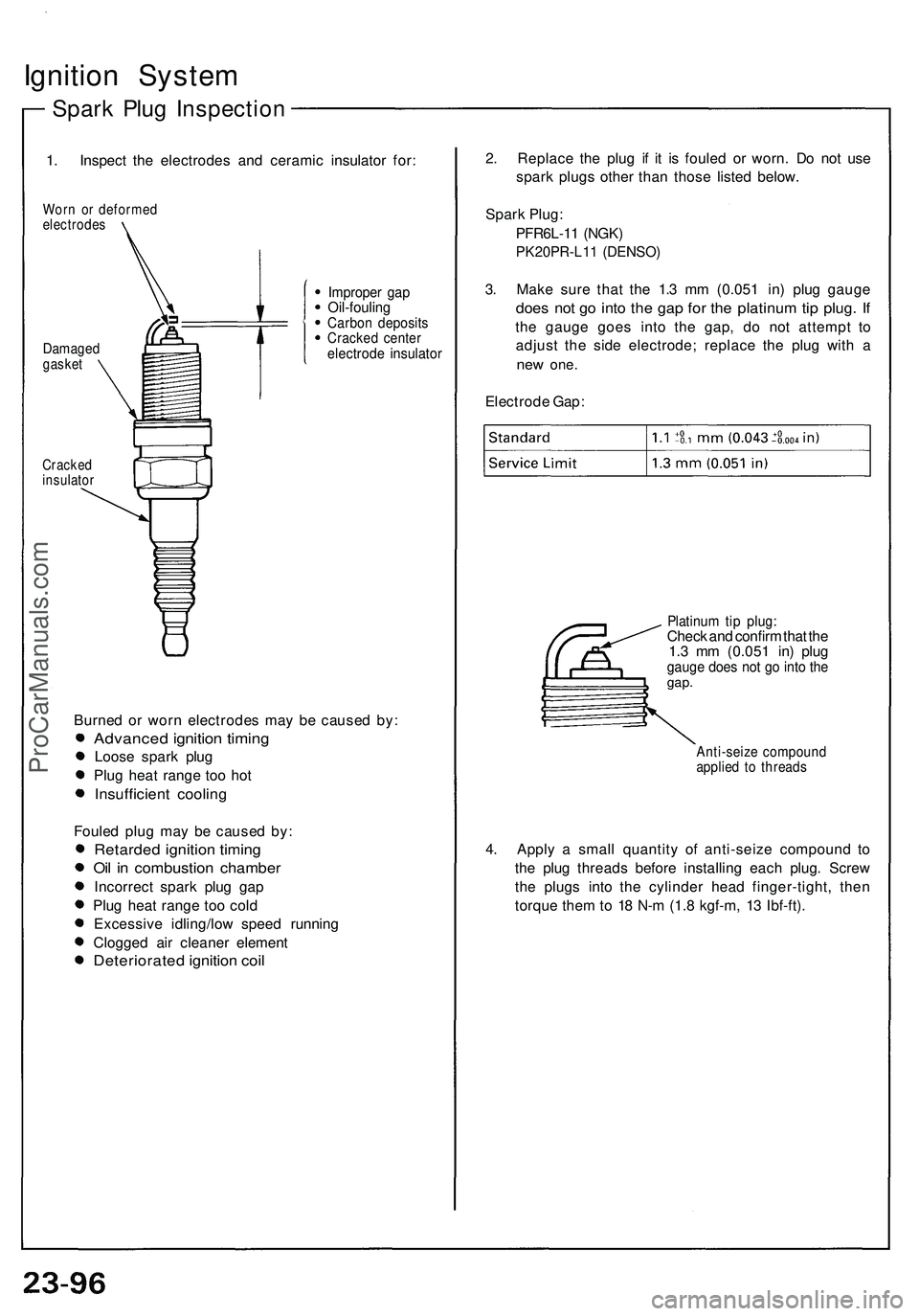
Spark Plug Inspection
1. Inspect the electrodes and ceramic insulator for:
Worn or deformed
electrodes
Cracked
insulator
Burned or worn electrodes may be caused by:
Advanced ignition timing
Loose spark plug
Plug heat range too hot
Insufficient cooling
Fouled plug may be caused by:
Retarded ignition timing
Oil in combustion chamber
Incorrect spark plug gap
Plug heat range too cold
Excessive idling/low speed running
Clogged air cleaner element
Deteriorated ignition coil
2. Replace the plug if it is fouled or worn. Do not use
spark plugs other than those listed below.
Spark Plug:
PFR6L-11 (NGK)
PK20PR-L11 (DENSO)
3. Make sure that the 1.3 mm (0.051 in) plug gauge
does not go into the gap for the platinum tip plug. If
the gauge goes into the gap, do not attempt to
adjust the side electrode; replace the plug with a
new
one.
Electrode Gap:
Platinum tip plug:
Check and confirm that the
1.3 mm (0.051 in) plug
gauge does not go into the
gap.
Anti-seize compound
applied to threads
4. Apply a small quantity of anti-seize compound to
the plug threads before installing each plug. Screw
the plugs into the cylinder head finger-tight, then
torque them to 18 N-m (1.8 kgf-m, 13 Ibf-ft).
Improper gap
Oil-fouling
Carbon deposits
Cracked center
electrode insulator
Damaged
gasketProCarManuals.com
Page 1268 of 1503
Noise Condenser Capacity Test
1. Use a commercially available condenser tester.
Connect the tester probes, and measure the con-
denser capacity.
Condenser capacity: 0.47 ±0.09 microfarads
POSITIVE TERMINAL
BODY GROUND
(Negative)
NOTE: The noise condenser is intended to reduce
ignition noise. However, condenser failure may
cause the engine to stop running.
2. If not within the specifications, replace the noise
condenser.ProCarManuals.com
Page 1304 of 1503

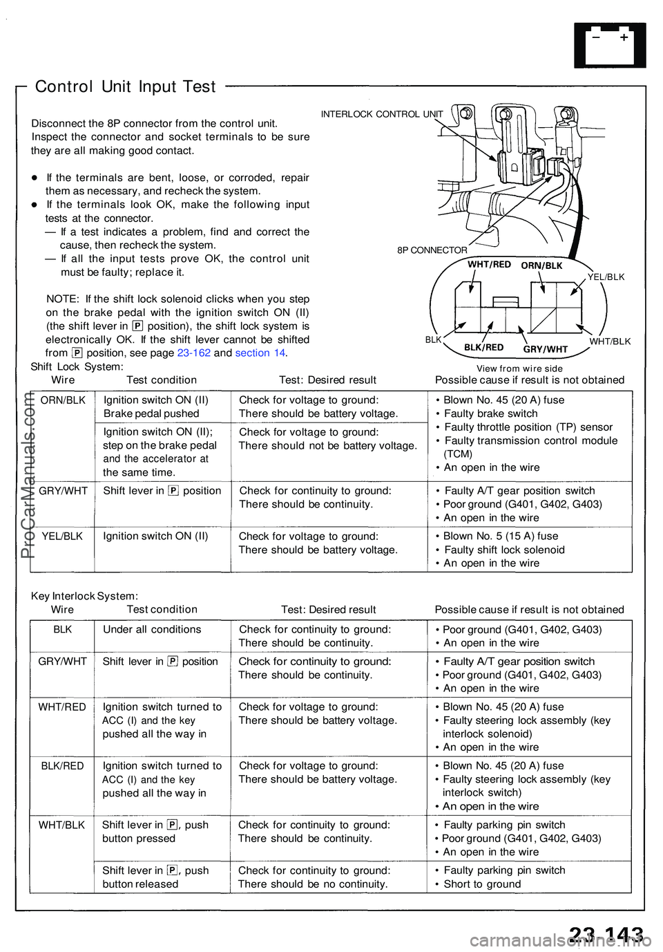
Control Uni t Inpu t Tes t
INTERLOC K CONTRO L UNI TDisconnec t th e 8 P connecto r fro m th e contro l unit .
Inspec t th e connecto r an d socke t terminal s t o b e sur e
the y ar e al l makin g goo d contact .
I f th e terminal s ar e bent , loose , o r corroded , repai r
the m as necessary , an d rechec k th e system .
I f th e terminal s loo k OK , mak e th e followin g inpu t
test s a t th e connector .
— If a tes t indicate s a problem , fin d an d correc t th e
cause , the n rechec k th e system .
— If al l th e inpu t test s prov e OK , th e contro l uni t
mus t b e faulty ; replac e it .
NOTE : I f th e shif t loc k solenoi d click s whe n yo u ste p
o n th e brak e peda l wit h th e ignitio n switc h O N (II )
(the shif t leve r i n position) , th e shif t loc k syste m is
electronicall y OK . I f th e shif t leve r canno t b e shifte d
from position , se e pag e 23-16 2 an d sectio n 14 .
Shif t Loc k System :
Wir e Tes t conditio n Test : Desire d resul t
8P CONNECTO R
BLK
YEL/BL K
WHT/BL K
View fro m wir e sid ePossibl e caus e if resul t i s no t obtaine d
ORN/BL K
GRY/WH T
YEL/BLK
Ignition switc h O N (II )
Brak e peda l pushe d
Ignitio n switc h O N (II) ;
ste p o n th e brak e peda l
and th e accelerato r a t
the sam e time .
Shift leve r i n positio n
Ignitio n switc h O N (II ) Chec
k fo r voltag e t o ground :
Ther e shoul d b e batter y voltage .
Chec k fo r voltag e t o ground :
Ther e shoul d no t b e batter y voltage .
Chec k fo r continuit y t o ground :
Ther e shoul d b e continuity .
Chec k fo r voltag e t o ground :
Ther e shoul d b e batter y voltage . •
Blow n No . 4 5 (2 0 A ) fus e
• Fault y brak e switc h
• Fault y throttl e positio n (TP ) senso r
• Fault y transmissio n contro l modul e
(TCM)
• A n ope n i n th e wir e
• Fault y A/ T gea r positio n switc h
• Poo r groun d (G401 , G402 , G403 )
• A n ope n i n th e wir e
• Blow n No . 5 (1 5 A ) fus e
• Fault y shif t loc k solenoi d
• A n ope n i n th e wir e
Ke y Interloc k System :
WireTes t conditio n
Test: Desire d resul t Possible caus e if resul t i s no t obtaine d
BLK
GRY/WH T
WHT/RE D
BLK/RED
WHT/BL K
Under al l condition s
Shift leve r i n positio n
Ignitio n switc h turne d t o
AC C (I ) an d th e ke y
pushe d al l th e wa y i n
Ignitio n switc h turne d t o
AC C (I ) an d th e ke y
pushe d al l th e wa y in
Shif t leve r i n pus h
butto n presse d
Shift leve r i n pus h
butto n release d Chec
k fo r continuit y t o ground :
Ther e shoul d b e continuity .
Check fo r continuit y t o ground :
There shoul d b e continuity .
Chec k fo r voltag e t o ground :
Ther e shoul d b e batter y voltage .
Chec k fo r voltag e t o ground :
Ther e shoul d b e batter y voltage .
Chec k fo r continuit y t o ground :
Ther e shoul d b e continuity .
Chec k fo r continuit y t o ground :
Ther e shoul d b e n o continuity . •
Poo r groun d (G401 , G402 , G403 )
• A n ope n i n th e wir e
• Fault y A/ T gea r positio n switc h
• Poo r groun d (G401 , G402 , G403 )
• A n ope n i n th e wir e
• Blow n No . 4 5 (2 0 A ) fus e
• Fault y steerin g loc k assembl y (ke y
interloc k solenoid )
• A n ope n i n th e wir e
• Blow n No . 4 5 (2 0 A ) fus e
• Fault y steerin g loc k assembl y (ke y
interloc k switch )
• A n ope n in th e wir e
• Fault y parkin g pi n switc h
• Poo r groun d (G401 , G402 , G403 )
• A n ope n i n th e wir e
• Fault y parkin g pi n switc h
• Shor t t o groun d
ProCarManuals.com
Page 1321 of 1503

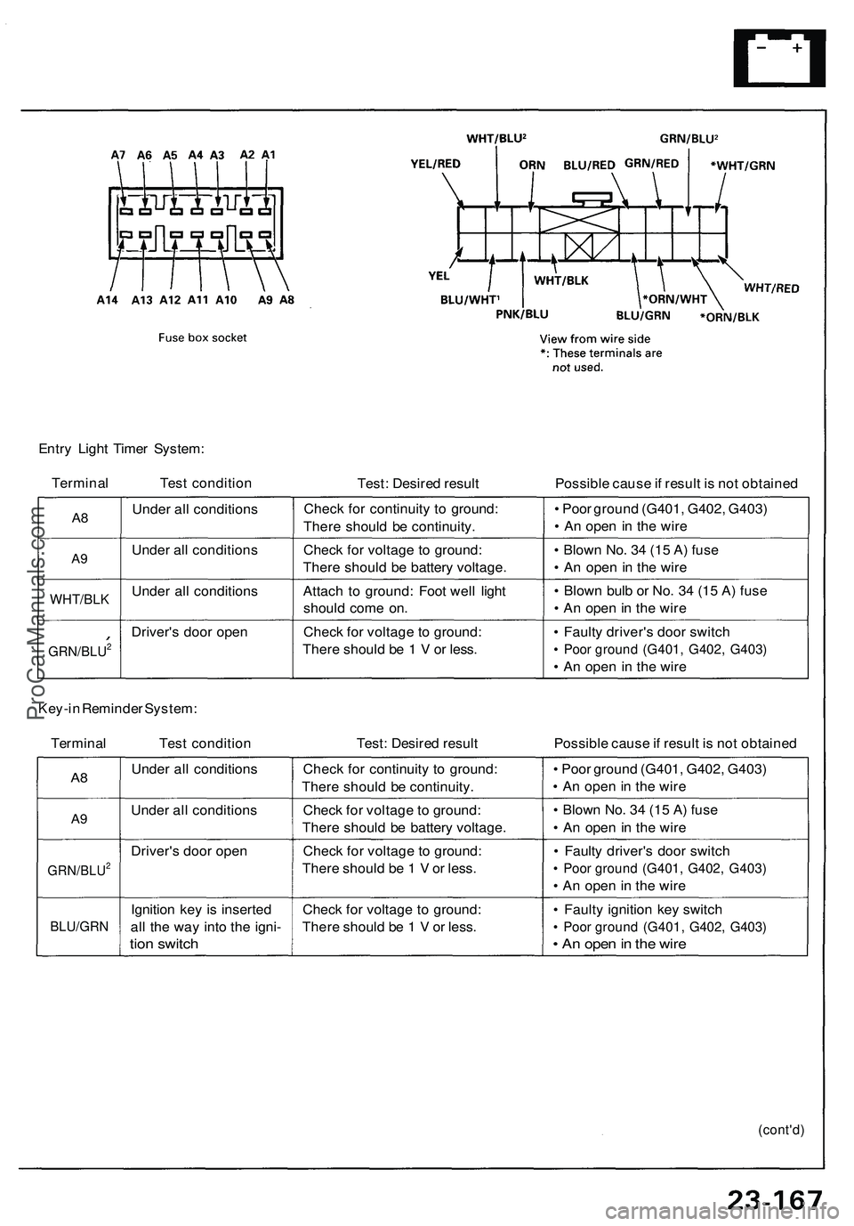
Entry Light Timer System:
Terminal Test condition
Test: Desired result
Possible cause if result is not obtained
A8
A9
WHT/BLK
GRN/BLU2
Under all conditions
Under all conditions
Under all conditions
Driver's door open
Check for continuity to ground:
There should be continuity.
Check for voltage to ground:
There should be battery voltage.
Attach to ground: Foot well light
should come on.
Check for voltage to ground:
There should be 1 V or less.
• Poor ground (G401, G402, G403)
• An open in the wire
• Blown No. 34 (15 A) fuse
• An open in the wire
• Blown bulb or No. 34 (15 A) fuse
• An open in the wire
• Faulty driver's door switch
• Poor ground (G401, G402, G403)
• An open in the wire
Key-in Reminder System:
Terminal Test condition
Test: Desired result
Possible cause if result is not obtained
A8
A9
GRN/BLU2
BLU/GRN
Under all conditions
Under all conditions
Driver's door open
Ignition key is inserted
all the way into the igni-
tion switch
Check for continuity to ground:
There should be continuity.
Check for voltage to ground:
There should be battery voltage.
Check for voltage to ground:
There should be 1 V or less.
Check for voltage to ground:
There should be 1 V or less.
• Poor ground (G401, G402, G403)
• An open in the wire
• Blown No. 34 (15 A) fuse
• An open in the wire
• Faulty driver's door switch
• Poor ground (G401, G402, G403)
• An open in the wire
• Faulty ignition key switch
• Poor ground (G401, G402, G403)
• An open in the wire
(cont'd)ProCarManuals.com