1997 ACURA NSX ignition
[x] Cancel search: ignitionPage 1466 of 1503
Immobilizer Syste m
Descriptio n
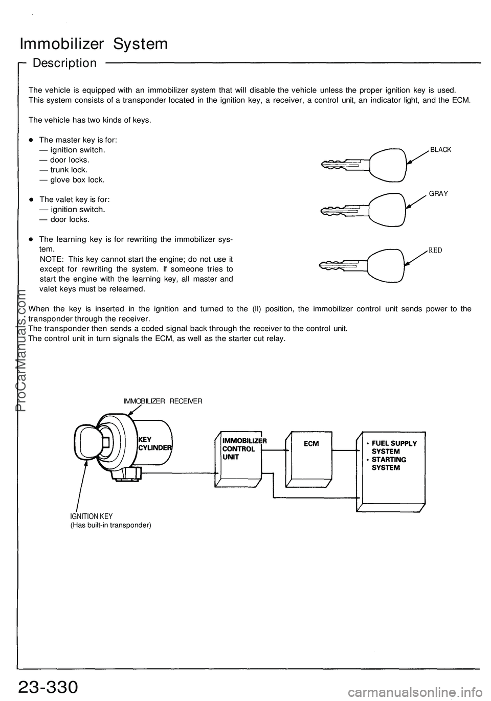
The vehicl e i s equippe d wit h a n immobilize r syste m tha t wil l disabl e th e vehicl e unles s th e prope r ignitio n ke y i s used .
Thi s syste m consist s o f a transponde r locate d i n th e ignitio n key , a receiver , a contro l unit , a n indicato r light , an d th e ECM .
Th e vehicl e ha s tw o kind s o f keys .
BLAC K
GRAY
The maste r ke y i s for :
— ignitio n switch .
— doo r locks .
— trun k lock .
— glov e bo x lock .
Th e vale t ke y i s for :
— ignitio n switch .
— doo r locks .
Th e learnin g ke y i s fo r rewritin g th e immobilize r sys -
tem.
NOTE : Thi s ke y canno t star t th e engine ; d o no t us e i t
excep t fo r rewritin g th e system . I f someon e trie s t o
star t th e engin e wit h th e learnin g key , al l maste r an d
vale t key s mus t b e relearned .
Whe n th e ke y i s inserte d i n th e ignitio n an d turne d t o th e (II ) position , th e immobilize r contro l uni t send s powe r t o th e
transponde r throug h th e receiver .
Th e transponde r the n send s a code d signa l bac k throug h th e receive r t o th e contro l unit .
Th e contro l uni t i n tur n signal s th e ECM , a s wel l a s th e starte r cu t relay .
RED
IMMOBILIZE R RECEIVE R
IGNITION KE Y(Has built-i n transponder )
23-330ProCarManuals.com
Page 1467 of 1503
IGNITION SWITCH
PROPER KEY
INSERTED
INDICATOR
LIGHT
WRONG KEY
INSERTED
INDICATOR
LIGHT
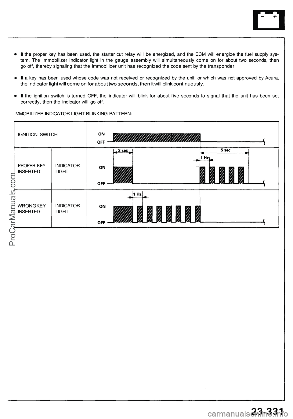
If the proper key has been used, the starter cut relay will be energized, and the ECM will energize the fuel supply sys-
tem. The immobilizer indicator light in the gauge assembly will simultaneously come on for about two seconds, then
go off, thereby signaling that the immobilizer unit has recognized the code sent by the transponder.
If a key has been used whose code was not received or recognized by the unit, or which was not approved by Acura,
the indicator light will come on for about two seconds, then it will blink continuously.
If the ignition switch is turned OFF, the indicator will blink for about five seconds to signal that the unit has been set
correctly, then the indicator will go off.
IMMOBILIZER INDICATOR LIGHT BLINKING PATTERN:ProCarManuals.com
Page 1469 of 1503
Immobilizer Syste m
Contro l Uni t Inpu t Tes t
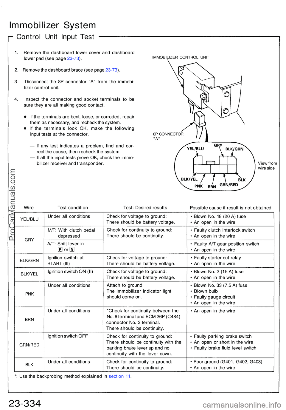
1. Remov e th e dashboar d lowe r cove r an d dashboar d
lowe r pa d (se e pag e 23-73 ).
2 . Remov e th e dashboar d brac e (se e pag e 23-73 ).
3 Disconnec t th e 8 P connecto r "A " fro m th e immobi -
lize r contro l unit .
4 . Inspec t th e connecto r an d socke t terminal s t o b e
sur e the y ar e al l makin g goo d contact .
I f th e terminal s ar e bent , loose , o r corroded , repai r
the m a s necessary , an d rechec k th e system .
I f th e terminal s loo k OK , mak e th e followin g
inpu t test s a t th e connector .
— If an y tes t indicate s a problem , fin d an d cor -
rec t th e cause , the n rechec k th e system .
— If al l th e inpu t test s prov e OK , chec k th e immo -
bilize r receive r an d transponder .IMMOBILIZER CONTRO L UNI T
8 P CONNECTO R
"A"
Vie w fro m
wir e side
Wir e Test conditio n Test: Desire d result s
Possible caus e if resul t i s no t obtaine d
YEL/BLU
GRY
BLK/GR N
BLK/YEL
PNK
BR N
GRN/RE D
BLK
Unde r al l condition s
M/T : Wit h clutc h peda l
depresse d
A/T: Shif t leve r i n
or
Ignitio n switc h a t
STAR T (III )
Ignitio n switc h O N (II )
Unde r al l condition s
Unde r al l condition s
Ignition switc h OF F
Unde r al l condition sChec
k fo r voltag e t o ground :
Ther e shoul d b e batter y voltage .
Chec k fo r continuit y t o ground :
Ther e shoul d b e continuity .
Chec k fo r voltag e t o ground :
Ther e shoul d b e batter y voltage .
Chec k fo r voltag e t o ground :
Ther e shoul d b e batter y voltage .
Attac h t o ground :
Th e immobilize r indicato r ligh t
shoul d com e on .
*Chec k fo r continuit y betwee n th e
No . 6 termina l an d EC M 26 P (C484 )
connecto r No . 3 terminal .
Ther e shoul d b e continuity .
Chec k fo r continuit y t o ground :
Ther e shoul d b e continuit y wit h th e
parkin g brak e leve r u p an d n o
continuit y wit h th e leve r down .
Chec k fo r continuit y t o ground :
Ther e shoul d b e continuity . •
Blow n No . 1 8 (2 0 A ) fus e
• A n ope n i n th e wir e
• Fault y clutc h interloc k switc h
• A n ope n i n th e wir e
• Fault y A/ T gea r positio n switc h
• A n ope n i n th e wir e
• Fault y starte r cu t rela y
• A n ope n i n th e wir e
• Blow n No . 2 (1 5 A ) fus e
• A n ope n i n th e wir e
• Blow n No . 3 3 (7. 5 A ) fus e
• Blow n bul b
• Fault y gaug e circui t
• A n ope n i n th e wir e
• A n ope n i n th e wir e
• Fault y parkin g brak e switc h
• A n ope n o r shor t i n th e wir e
• Fault y brak e flui d leve l switc h
• Poo r groun d (G401 , G402 , G403 )
• A n ope n i n th e wir e
* : Us e th e backprobin g metho d explaine d i n sectio n 11 .
23-33 4ProCarManuals.com
Page 1470 of 1503
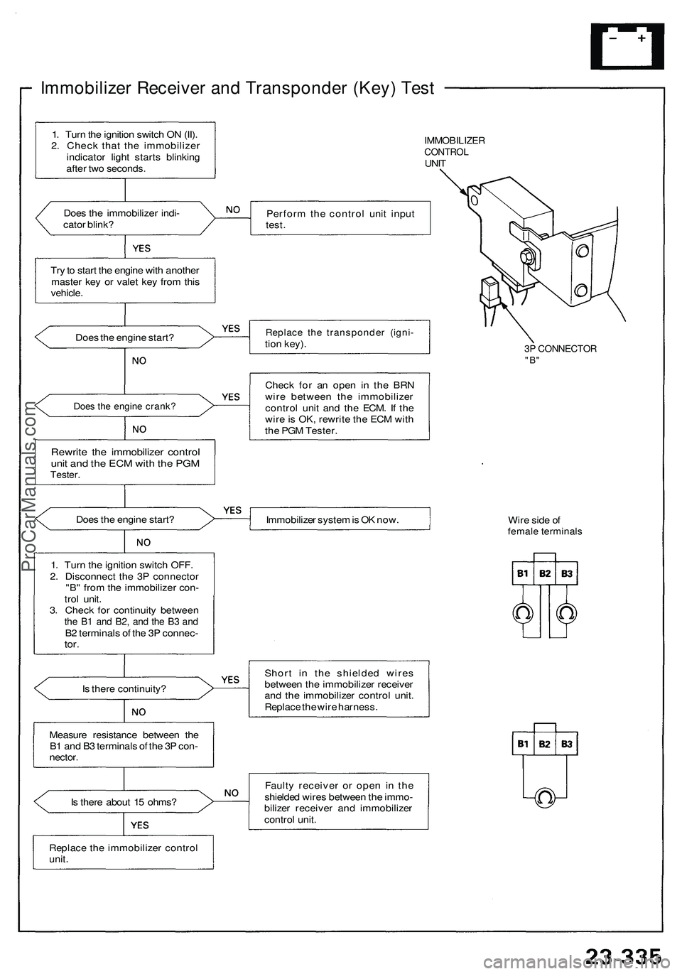
Immobilizer Receiver and Transponder (Key) Test
IMMOBILIZER
CONTROL
UNIT
Does the immobilizer indi-
cator blink?
Perform the control unit input
test.
Try to start the engine with another
master key or valet key from this
vehicle.
Does the engine start?
Replace the transponder (igni-
tion key).
3P CONNECTOR
"B"
Does the engine crank?
Rewrite the immobilizer control
unit and the ECM with the PGM
Tester.
Check for an open in the BRN
wire between the immobilizer
control unit and the ECM. If the
wire is OK, rewrite the ECM with
the PGM Tester.
Does the engine start?
Immobilizer system is OK now.
Wire side of
female terminals
Is there continuity?
Short in the shielded wires
between the immobilizer receiver
and the immobilizer control unit.
Replace the wire harness.
Measure resistance between the
B1 and B3 terminals of the 3P con-
nector.
Is there about 15 ohms?
Faulty receiver or open in the
shielded wires between the immo-
bilizer receiver and immobilizer
control unit.
Replace the immobilizer control
unit.
1. Turn the ignition switch ON (II).
2. Check that the immobilizer
indicator light starts blinking
after two seconds.
1. Turn the ignition switch OFF.
2. Disconnect the 3P connector
"B" from the immobilizer con-
trol unit.
3. Check for continuity between
the B1 and B2, and the B3 and
B2 terminals of the 3P connec-
tor.ProCarManuals.com
Page 1471 of 1503
Immobilizer Syste m
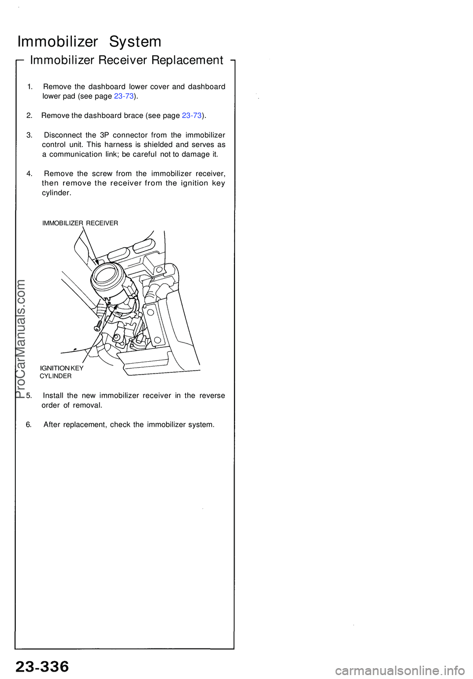
Immobilize r Receive r Replacemen t
1. Remov e th e dashboar d lowe r cove r an d dashboar d
lowe r pa d (se e pag e 23-73 ).
2 . Remov e th e dashboar d brac e (se e pag e 23-73 ).
3 . Disconnec t th e 3 P connecto r fro m th e immobilize r
contro l unit . Thi s harnes s i s shielde d an d serve s a s
a communicatio n link ; b e carefu l no t t o damag e it .
4 . Remov e th e scre w fro m th e immobilize r receiver ,
then remov e th e receive r fro m th e ignitio n ke y
cylinder .
IMMOBILIZE R RECEIVE R
IGNITION KEYCYLINDE R
5. Instal l th e ne w immobilize r receive r i n th e revers e
orde r o f removal .
6 . Afte r replacement , chec k th e immobilize r system .
ProCarManuals.com
Page 1477 of 1503
Supplemental Restraint System (SRS)
Steering-related Precautions
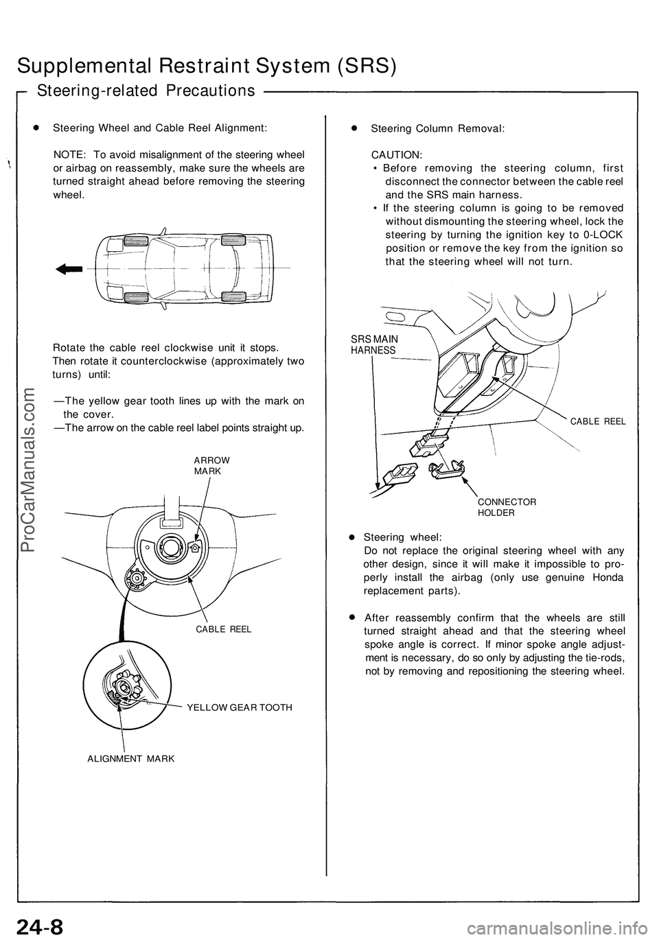
Steering Wheel and Cable Reel Alignment:
NOTE: To avoid misalignment of the steering wheel
or airbag on reassembly, make sure the wheels are
turned straight ahead before removing the steering
wheel.
Rotate the cable reel clockwise unit it stops.
Then rotate it counterclockwise (approximately two
turns) until:
—The yellow gear tooth lines up with the mark on
the cover.
—The arrow on the cable reel label points straight up.
ARROW
MARK
YELLOW GEAR TOOTH
ALIGNMENT MARK
Steering Column Removal:
CAUTION:
• Before removing the steering column, first
disconnect the connector between the cable reel
and the SRS main harness.
• If the steering column is going to be removed
without dismounting the steering wheel, lock the
steering by turning the ignition key to 0-LOCK
position or remove the key from the ignition so
that the steering wheel will not turn.
SRS MAIN
HARNESS
CABLE REEL
CONNECTOR
HOLDER
Steering wheel:
Do not replace the original steering wheel with any
other design, since it will make it impossible to pro-
perly install the airbag (only use genuine Honda
replacement parts).
After reassembly confirm that the wheels are still
turned straight ahead and that the steering wheel
spoke angle is correct. If minor spoke angle adjust-
ment is necessary, do so only by adjusting the tie-rods,
not by removing and repositioning the steering wheel.
CABLE REELProCarManuals.com
Page 1501 of 1503
Supplemental Restraint System (SRS)
SRS Unit Assembly Installation
CAUTION: Be sure to install the SRS wiring so that it is
not pinched or interfering with other car parts.
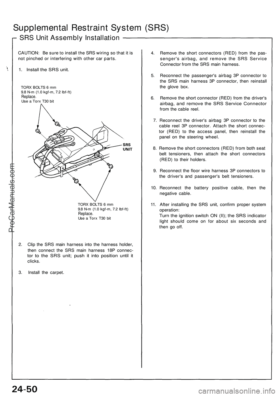
1. Install the SRS unit.
TORX BOLTS 6 mm
9.8 N-m (1.0 kgf-m, 7.2 Ibf-ft)
Replace.
Use a Torx T30 bit
TORX BOLTS 6 mm
9.8 N-m (1.0 kgf-m, 7.2 Ibf-ft)
Replace.
Use a Torx T30 bit
2. Clip the SRS main harness into the harness holder,
then connect the SRS main harness 18P connec-
tor to the SRS unit; push it into position until it
clicks.
3. Install the carpet.
4. Remove the short connectors (RED) from the pas-
senger's airbag, and remove the SRS Service
Connector from the SRS main harness.
5. Reconnect the passenger's airbag 3P connector to
the SRS main harness 3P connector, then reinstall
the glove box.
6. Remove the short connector (RED) from the driver's
airbag, and remove the SRS Service Connector
from the cable reel.
7. Reconnect the driver's airbag 3P connector to the
cable reel 3P connector. Attach the short connec-
tor (RED) to the access panel, then reinstall the
panel on the steering wheel.
8. Remove the short connectors (RED) from both seat
belt tensioners, then attach the short connectors
(RED) to their holders.
9. Reconnect the floor wire harness 3P connectors to
the driver's and passenger's belt tensioners.
10. Reconnect the battery positive cable, then the
negative cable.
11. After installing the SRS unit, confirm proper system
operation:
Turn the ignition switch ON (II); the SRS indicator
light should come on for about six seconds and
then go off.ProCarManuals.com