1997 ACURA NSX weight
[x] Cancel search: weightPage 32 of 1503

The numbers in the middle of the API Service label tell
you the oil's SAE viscosity or weight. Select the oil for
your vehicle according to this chart:
Ambient Temperature
An oil with a viscosity of 10W - 30 is preferred for
improved fuel economy and year-round protection in the
vehicle.
You may use a 5W - 30 oil if the climate in your area is
limited to the temperature range shown on the chart.
API CERTIFICATION SEAL
API SERVICE LABEL
4. Run the engine for more than three minutes, then
check for oil leakage and oil level.ProCarManuals.com
Page 275 of 1503
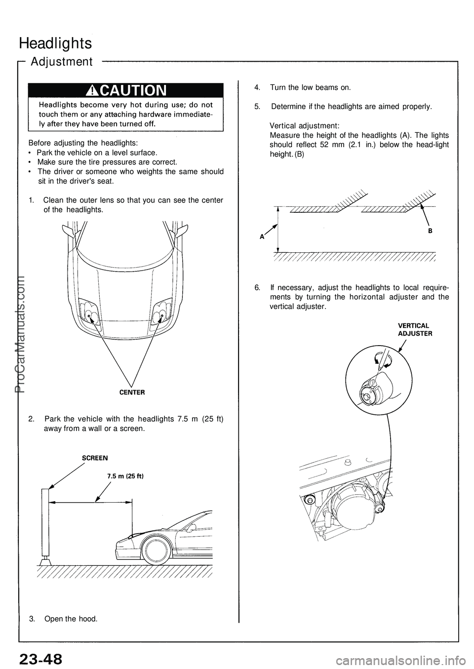
Headlights
Adjustmen t
Before adjustin g th e headlights :
• Par k th e vehicl e o n a leve l surface .
• Mak e sur e th e tir e pressure s ar e correct .
• Th e drive r o r someon e wh o weight s th e sam e shoul d
si t i n th e driver' s seat .
1 . Clea n th e oute r len s s o tha t yo u ca n se e th e cente r
o f th e headlights . 4
. Tur n th e lo w beam s on .
5 . Determin e i f th e headlight s ar e aime d properly .
Vertica l adjustment :
Measur e th e heigh t o f th e headlight s (A) . Th e light s
shoul d reflec t 5 2 m m (2. 1 in. ) belo w th e head-ligh t
height. (B)
6. I f necessary , adjus t th e headlight s t o loca l require -
ment s b y turnin g th e horizonta l adjuste r an d th e
vertica l adjuster .
2 . Par k th e vehicl e wit h th e headlight s 7. 5 m (2 5 ft )
awa y fro m a wal l o r a screen .
3 . Ope n th e hood .
ProCarManuals.com
Page 368 of 1503
3-13
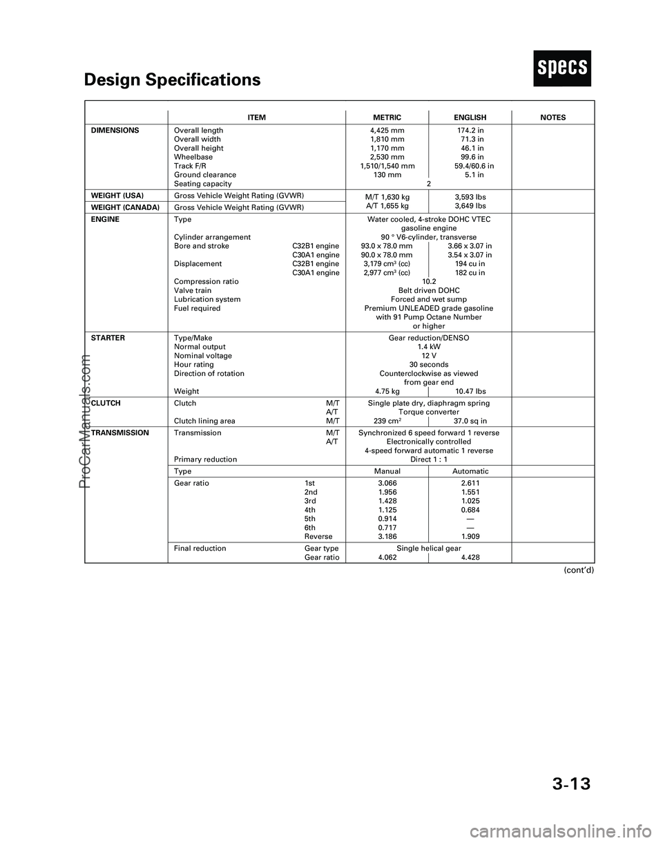
TDesign Specifications
(cont’d)
ITEMMETRICENGLISH
DIMENSIONSOverall length
Overall width
Overall height
Wheelbase
Track F/R
Ground clearance
Seating capacity4,425 mm 174.2 in
1,810 mm 71.3 in
1,170 mm 46.1 in
2,530 mm 99.6 in
1,510/1,540 mm 59.4/60.6 in
130 mm 5.1 in
2
WEIGHT (USA)
Single plate dry, diaphragm spring
Torque converter
239 cm
237.0 sq in
CLUTCHClutch M/T
A/T
Clutch lining area M/T
Gross Vehicle Weight Rating (GVWR)
NOTES
Gear reduction/DENSO
1.4 kW
12 V
30 seconds
Counterclockwise as viewed
from gear end
4.75 kg 10.47 lbs
ENGINEWater cooled, 4-stroke DOHC VTEC
gasoline engine
90 °V6-cylinder, transverse
93.0 x 78.0 mm 3.66 x 3.07 in
90.0 x 78.0 mm 3.54 x 3.07 in
3,179 cm
3(cc) 194 cu in
2,977 cm3(cc) 182 cu in
10.2
Belt driven DOHC
Forced and wet sump
Premium UNLEADED grade gasoline
with 91 Pump Octane Number
or higher
STARTERType/Make
Normal output
Nominal voltage
Hour rating
Direction of rotation
Weight
WEIGHT (CANADA)Gross Vehicle Weight Rating (GVWR)
Synchronized 6 speed forward 1 reverse
Electronically controlled
4-speed forward automatic 1 reverse
Direct 1 : 1Transmission M/T
A/T
Primary reduction
Manual AutomaticType
3.066 2.611
1.956 1.551
1.428 1.025
1.125 0.684
0.914—
0.717—
3.186 1.909Gear ratio 1st
2nd
3rd
4th
5th
6th
Reverse
Single helical gear
4.062 4.428
TRANSMISSION
Final reduction Gear type
Gear ratio
Type
Cylinder arrangement
Bore and strokeC32B1 engine
C30A1 engine
DisplacementC32B1 engine
C30A1 engine
Compression ratio
Valve train
Lubrication system
Fuel required
M/T 1,630 kg 3,593 lbs
A/T 1,655 kg 3,649 lbs
*04-NSX (61SW004)SEC03(01-16) 9/22/04 1:49 PM Page 3-13
ProCarManuals.com
Page 384 of 1503
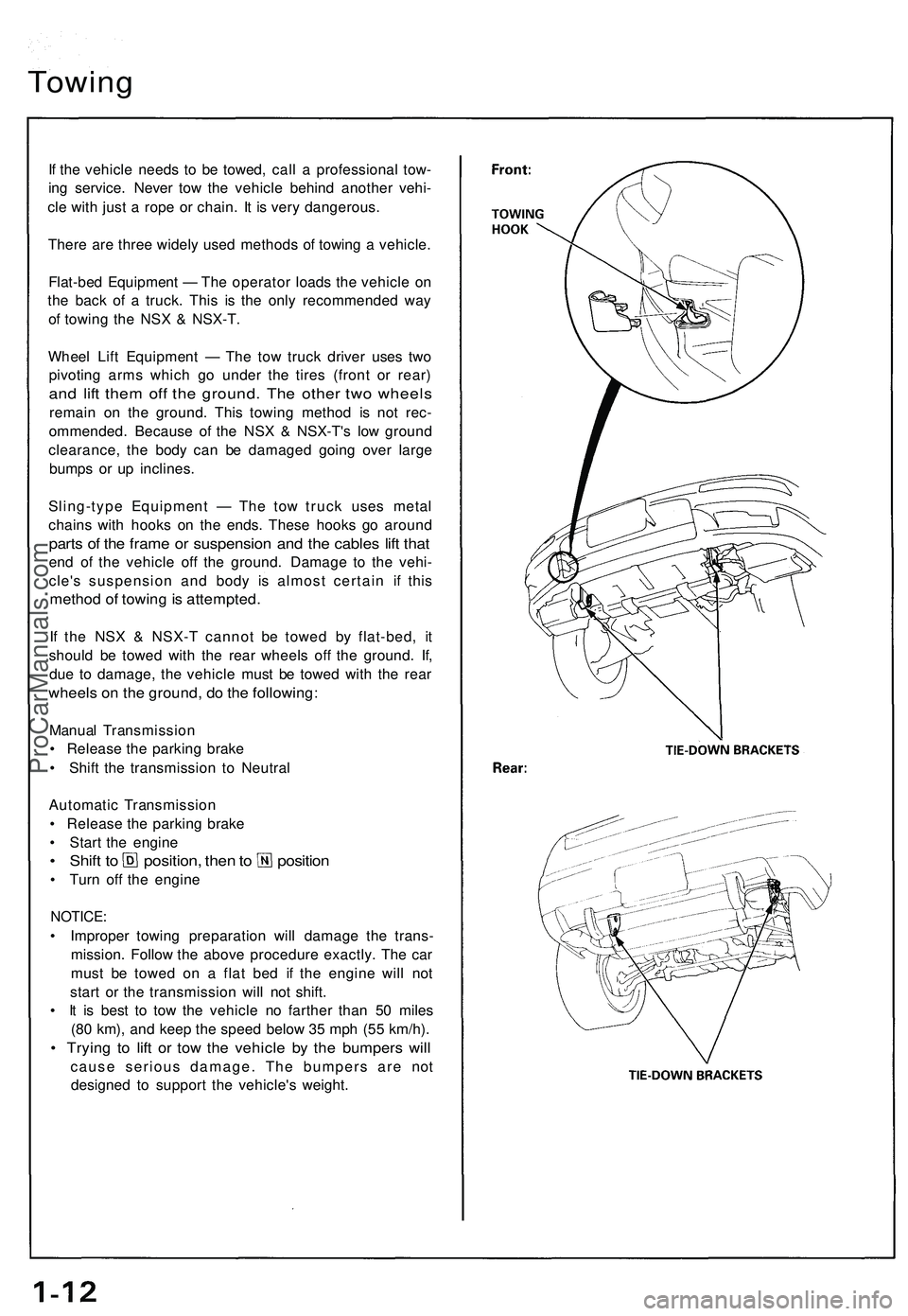
Towing
If the vehicle needs to be towed, call a professional tow-
ing service. Never tow the vehicle behind another vehi-
cle with just a rope or chain. It is very dangerous.
There are three widely used methods of towing a vehicle.
Flat-bed Equipment — The operator loads the vehicle on
the back of a truck. This is the only recommended way
of towing the NSX & NSX-T.
Wheel Lift Equipment — The tow truck driver uses two
pivoting arms which go under the tires (front or rear)
and lift them off the ground. The other two wheels
remain on the ground. This towing method is not rec-
ommended. Because of the NSX & NSX-T's low ground
clearance, the body can be damaged going over large
bumps or up inclines.
Sling-type Equipment — The tow truck uses metal
chains with hooks on the ends. These hooks go around
parts of the frame or suspension and the cables lift that
end of the vehicle off the ground. Damage to the vehi-
cle's suspension and body is almost certain if this
method of towing is attempted.
If the NSX & NSX-T cannot be towed by flat-bed, it
should be towed with the rear wheels off the ground. If,
due to damage, the vehicle must be towed with the rear
wheels on the ground, do the following:
Manual Transmission
• Release the parking brake
• Shift the transmission to Neutral
Automatic Transmission
• Release the parking brake
• Start the engine
• Shift to position, then to position
• Turn off the engine
NOTICE:
• Improper towing preparation will damage the trans-
mission. Follow the above procedure exactly. The car
must be towed on a flat bed if the engine will not
start or the transmission will not shift.
• It is best to tow the vehicle no farther than 50 miles
(80 km), and keep the speed below 35 mph (55 km/h).
• Trying to lift or tow the vehicle by the bumpers will
cause serious damage. The bumpers are not
designed to support the vehicle's weight.ProCarManuals.com
Page 478 of 1503
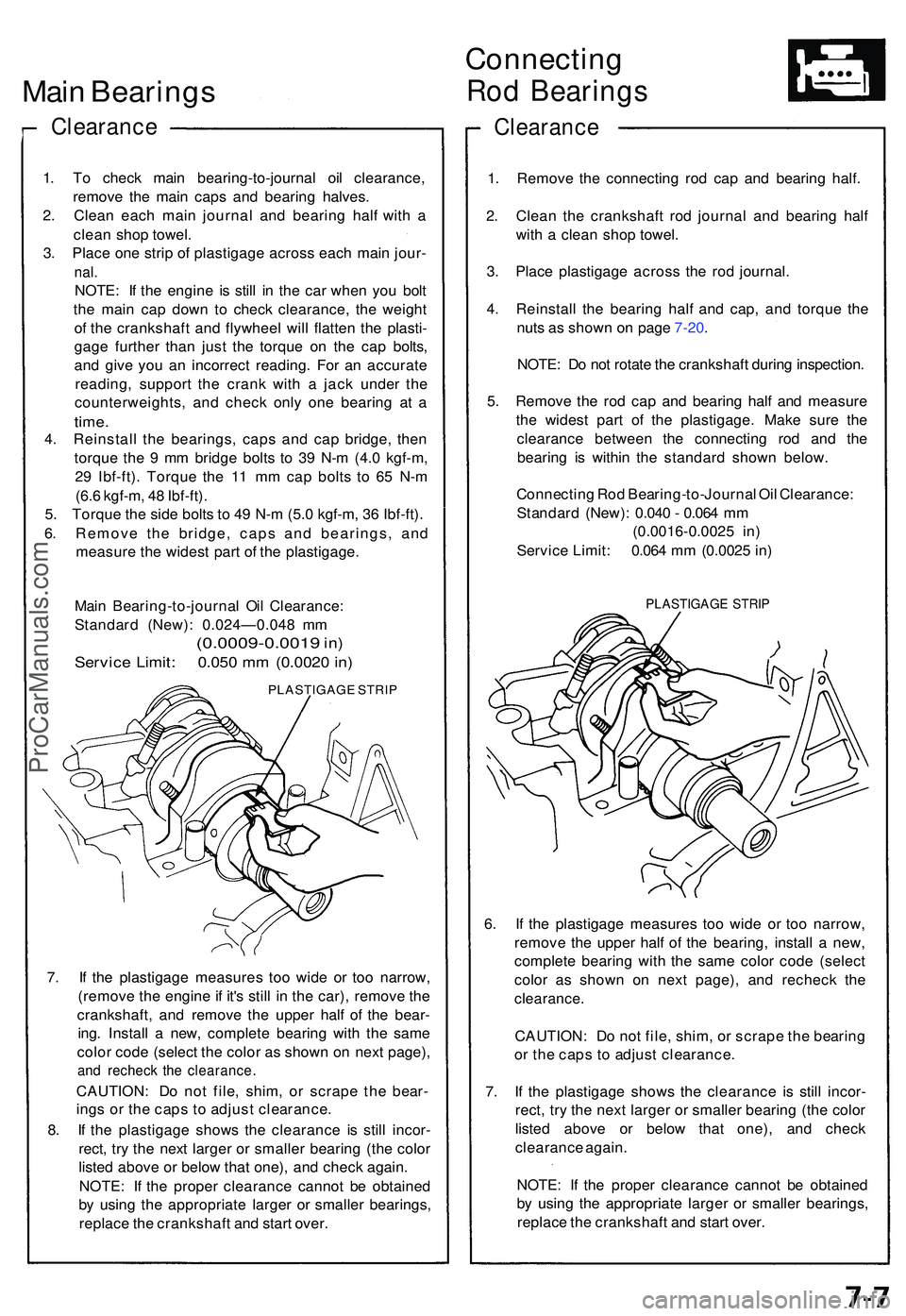
Main Bearing s
Clearanc e
1. T o chec k mai n bearing-to-journa l oi l clearance ,
remov e th e mai n cap s an d bearin g halves .
2 . Clea n eac h mai n journa l an d bearin g hal f wit h a
clea n sho p towel .
3 . Plac e on e stri p o f plastigag e acros s eac h mai n jour -
nal.
NOTE : I f th e engin e i s stil l i n th e ca r whe n yo u bol t
th e mai n ca p dow n t o chec k clearance , th e weigh t
o f th e crankshaf t an d flywhee l wil l flatte n th e plasti -
gag e furthe r tha n jus t th e torqu e o n th e ca p bolts ,
an d giv e yo u a n incorrec t reading . Fo r a n accurat e
reading , suppor t th e cran k wit h a jac k unde r th e
counterweights , an d chec k onl y on e bearin g a t a
time .
4. Reinstal l th e bearings , cap s an d ca p bridge , the n
torqu e th e 9 m m bridg e bolt s t o 3 9 N- m (4. 0 kgf-m ,
2 9 Ibf-ft) . Torqu e th e 1 1 m m ca p bolt s t o 6 5 N- m
(6. 6 kgf-m , 4 8 Ibf-ft) .
5 . Torqu e th e sid e bolt s t o 4 9 N- m (5. 0 kgf-m , 3 6 Ibf-ft) .
6 . Remov e th e bridge , cap s an d bearings , an d
measur e th e wides t par t o f th e plastigage .
Mai n Bearing-to-journa l Oi l Clearance :
Standar d (New) : 0.024—0.04 8 m m
(0.0009-0.0019 in)
Servic e Limit : 0.05 0 m m (0.002 0 in )
PLASTIGAG E STRI P
7. I f th e plastigag e measure s to o wid e o r to o narrow ,
(remov e th e engin e if it' s stil l i n th e car) , remov e th e
crankshaft , an d remov e th e uppe r hal f o f th e bear -
ing . Instal l a new , complet e bearin g wit h th e sam e
colo r cod e (selec t th e colo r a s show n o n nex t page) ,
and rechec k th e clearance .
CAUTION: D o no t file , shim , o r scrap e the bear -
ing s o r th e cap s t o adjus t clearance .
8 . I f th e plastigag e show s th e clearanc e i s stil l incor -
rect , tr y th e nex t large r o r smalle r bearin g (th e colo r
liste d abov e o r belo w tha t one) , an d chec k again .
NOTE : I f th e prope r clearanc e canno t b e obtaine d
b y usin g th e appropriat e large r o r smalle r bearings ,
replac e th e crankshaf t an d star t over .
Connectin g
Rod Bearing s
Clearanc e
1. Remov e th e connectin g ro d ca p an d bearin g half .
2 . Clea n th e crankshaf t ro d journa l an d bearin g hal f
wit h a clea n sho p towel .
3 . Plac e plastigag e acros s th e ro d journal .
4 . Reinstal l th e bearin g hal f an d cap , an d torqu e th e
nut s a s show n o n pag e 7-20 .
NOTE : D o no t rotat e th e crankshaf t durin g inspection .
5 . Remov e th e ro d ca p an d bearin g hal f an d measur e
th e wides t par t o f th e plastigage . Mak e sur e th e
clearanc e betwee n th e connectin g ro d an d th e
bearin g i s withi n th e standar d show n below .
Connectin g Ro d Bearing-to-Journa l Oi l Clearance :
Standar d (New) : 0.04 0 - 0.06 4 m m
(0.0016-0.002 5 in )
Servic e Limit : 0.06 4 m m (0.002 5 in )
PLASTIGAG E STRI P
6. I f th e plastigag e measure s to o wid e o r to o narrow ,
remov e th e uppe r hal f o f th e bearing , instal l a new ,
complet e bearin g wit h th e sam e colo r cod e (selec t
colo r a s show n o n nex t page) , an d rechec k th e
clearance .
CAUTION : D o no t file , shim , o r scrap e th e bearin g
o r th e cap s t o adjus t clearance .
7 . I f th e plastigag e show s th e clearanc e i s stil l incor -
rect , tr y th e nex t large r o r smalle r bearin g (th e colo r
liste d abov e o r belo w tha t one) , an d chec k
clearanc e again .
NOTE : I f th e prope r clearanc e canno t b e obtaine d
b y usin g th e appropriat e large r o r smalle r bearings ,
replac e th e crankshaf t an d star t over .
ProCarManuals.com
Page 503 of 1503
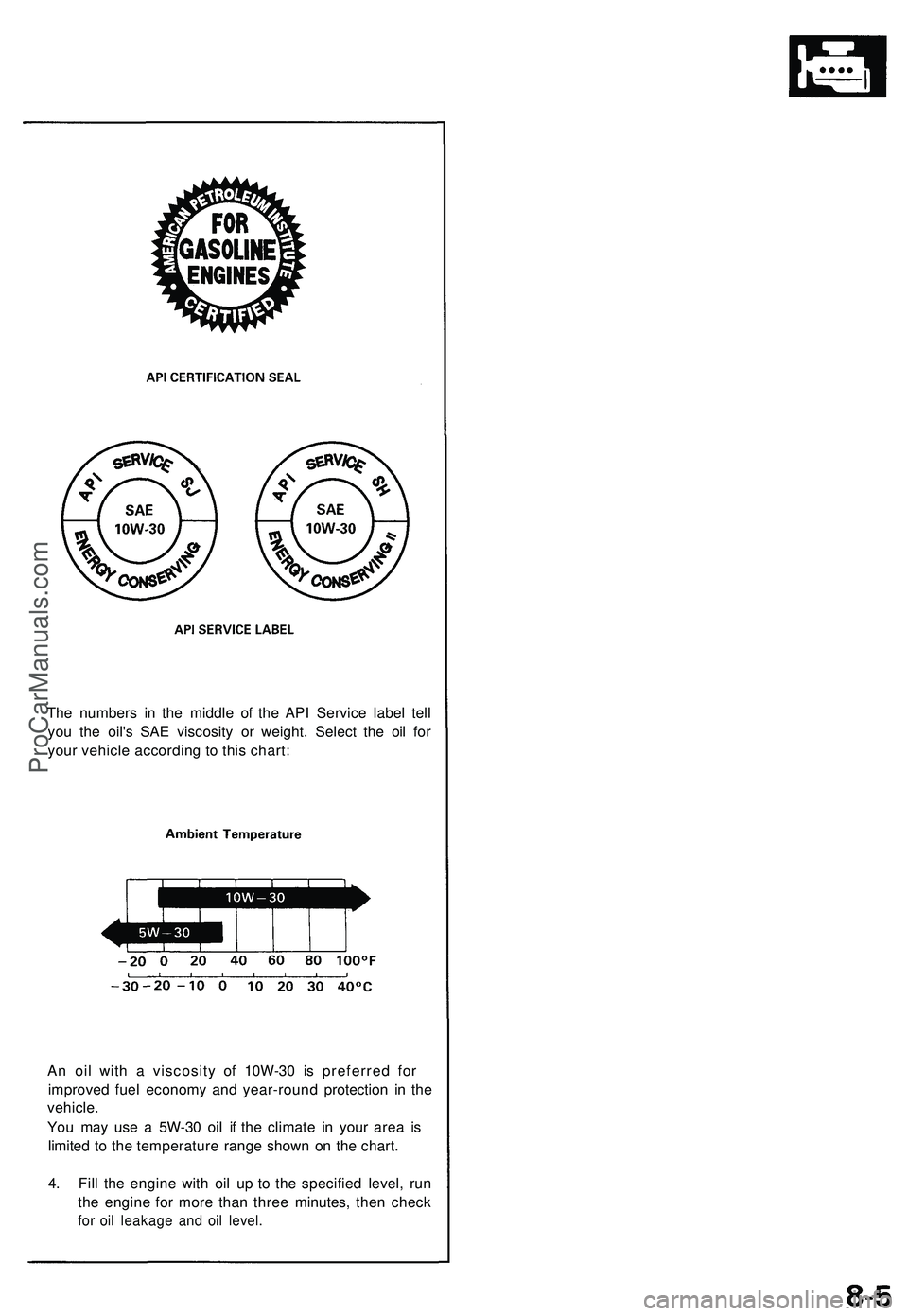
The number s i n th e middl e o f th e AP I Servic e labe l tel l
yo u th e oil' s SA E viscosit y o r weight . Selec t th e oi l fo r
you r vehicl e accordin g t o thi s chart :
A n oi l wit h a viscosit y o f 10 W-3 0 i s preferre d fo r
improve d fue l econom y an d year-roun d protection in th e
vehicle .
Yo u ma y us e a 5 W-3 0 oi l i f th e climat e i n you r are a i s
limite d t o th e temperatur e rang e show n o n th e chart .
4 . Fil l th e engin e wit h oi l u p t o th e specifie d level , ru n
th e engin e fo r mor e tha n thre e minutes , the n chec k
for oi l leakag e an d oi l level .
ProCarManuals.com
Page 663 of 1503
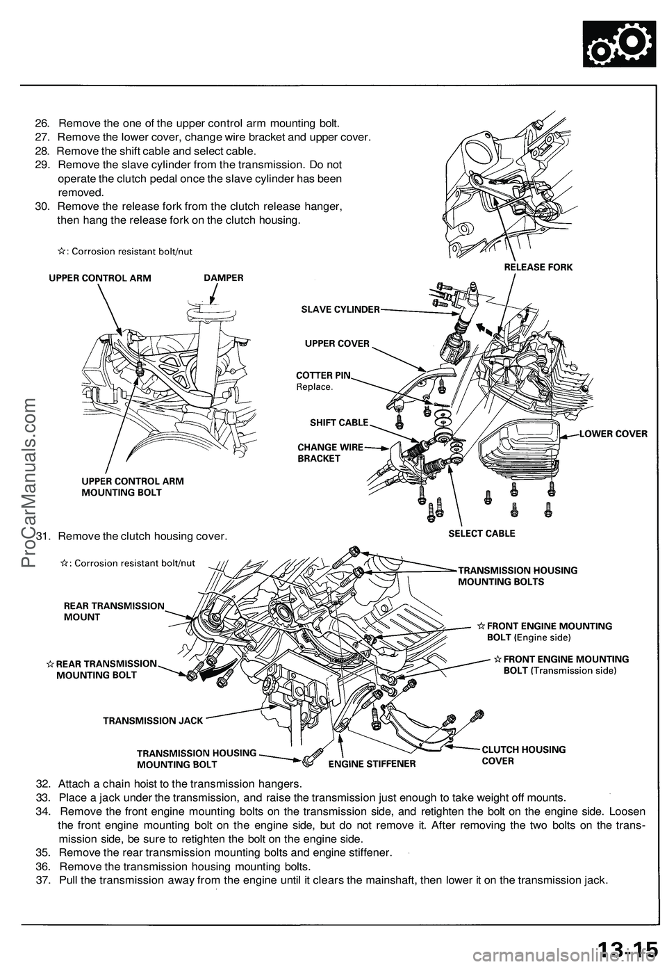
32. Attach a chain hoist to the transmission hangers.
33. Place a jack under the transmission, and raise the transmission just enough to take weight off mounts.
34. Remove the front engine mounting bolts on the transmission side, and retighten the bolt on the engine side. Loosen
the front engine mounting bolt on the engine side, but do not remove it. After removing the two bolts on the trans-
mission side, be sure to retighten the bolt on the engine side.
35. Remove the rear transmission mounting bolts and engine stiffener.
36. Remove the transmission housing mounting bolts.
37. Pull the transmission away from the engine until it clears the mainshaft, then lower it on the transmission jack.
26. Remove the one of the upper control arm mounting bolt.
27. Remove the lower cover, change wire bracket and upper cover.
28. Remove the shift cable and select cable.
29. Remove the slave cylinder from the transmission. Do not
operate the clutch pedal once the slave cylinder has been
removed.
30. Remove the release fork from the clutch release hanger,
then hang the release fork on the clutch housing.
31. Remove the clutch housing cover.ProCarManuals.com
Page 781 of 1503
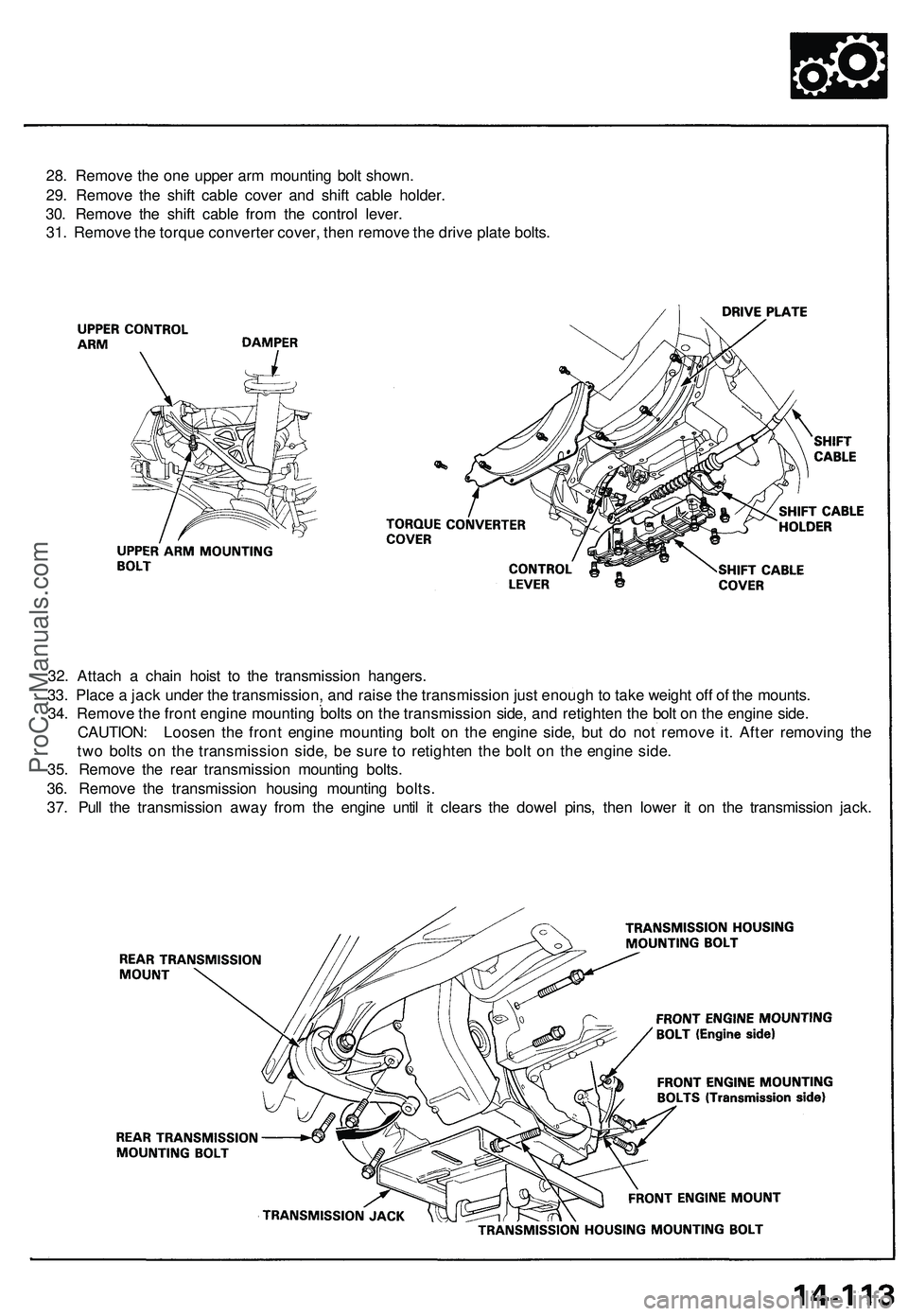
28. Remove the one upper arm mounting bolt shown.
29. Remove the shift cable cover and shift cable holder.
30. Remove the shift cable from the control lever.
31. Remove the torque converter cover, then remove the drive plate bolts.
32. Attach a chain hoist to the transmission hangers.
33. Place a jack under the transmission, and raise the transmission just enough to take weight off of the mounts.
34. Remove the front engine mounting bolts on the transmission side, and retighten the bolt on the engine side.
CAUTION: Loosen the front engine mounting bolt on the engine side, but do not remove it. After removing the
two bolts on the transmission side, be sure to retighten the bolt on the engine side.
35. Remove the rear transmission mounting bolts.
36. Remove the transmission housing mounting bolts.
37. Pull the transmission away from the engine until it clears the dowel pins, then lower it on the transmission jack.ProCarManuals.com