Page 791 of 1503
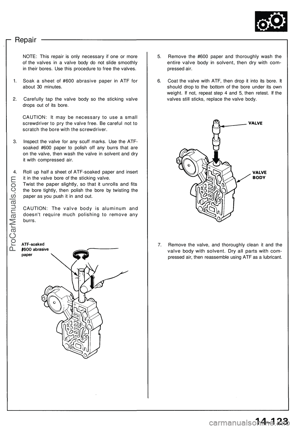
Repair
5. Remov e th e #60 0 pape r an d thoroughl y was h th e
entir e valv e bod y i n solvent , the n dr y wit h com -
presse d air .
6 . Coa t th e valv e wit h ATF , the n dro p i t int o it s bore . I t
shoul d dro p t o th e botto m o f th e bor e unde r it s ow n
weight . I f not , repea t ste p 4 an d 5 , the n retest . I f th e
valve s stil l sticks , replac e th e valv e body .
NOTE
: Thi s repai r i s onl y necessar y i f on e o r mor e
o f th e valve s i n a valv e bod y d o no t slid e smoothl y
i n thei r bores . Us e thi s procedur e t o fre e th e valves .
1 . Soa k a shee t o f #60 0 abrasiv e pape r i n AT F fo r
abou t 3 0 minutes .
2 . Carefull y ta p th e valv e bod y s o th e stickin g valv e
drop s ou t o f it s bore .
CAUTION : I t ma y b e necessar y t o us e a smal l
screwdrive r t o pr y th e valv e free . B e carefu l no t t o
scratc h th e bor e wit h th e screwdriver .
3 . Inspec t th e valv e fo r an y scuf f marks . Us e th e ATF -
soake d #60 0 pape r t o polis h of f an y burr s tha t ar e
o n th e valve , the n was h th e valv e i n solven t an d dr y
i t wit h compresse d air .
4 . Rol l u p hal f a shee t o f ATF-soake d pape r an d inser t
i t i n th e valv e bor e o f th e stickin g valve .
Twist th e pape r slightly , s o tha t i t unroll s an d fit s
the bor e tightly , the n polis h th e bor e b y twistin g th e
pape r a s yo u pus h i t i n an d out .
CAUTION : Th e valv e bod y i s aluminu m an d
doesn' t requir e muc h polishin g t o remov e an y
burrs .
7. Remov e th e valve , an d thoroughl y clea n i t an d th e
valv e bod y wit h solvent . Dr y al l part s wit h com -
presse d air , the n reassembl e usin g AT F a s a lubricant .
ProCarManuals.com
Page 937 of 1503
System Description
Suspension Composition
Outline
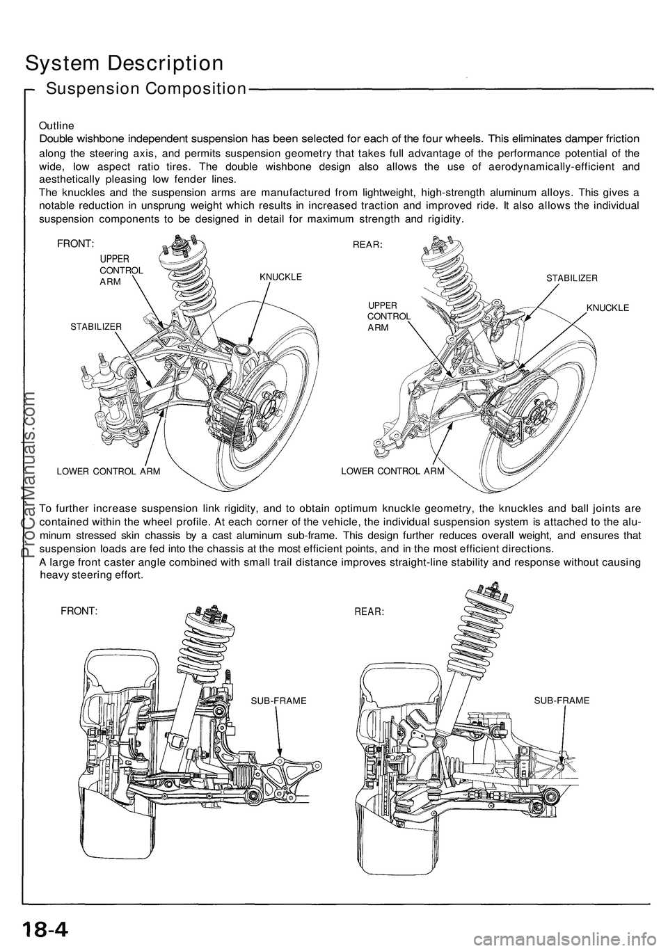
Double wishbon e independen t suspensio n ha s bee n selecte d fo r eac h o f th e fou r wheels . Thi s eliminate s dampe r frictio n
along th e steerin g axis , an d permit s suspensio n geometr y tha t take s ful l advantag e o f th e performanc e potentia l o f th e
wide , lo w aspec t rati o tires . Th e doubl e wishbon e desig n als o allow s th e us e o f aerodynamically-efficien t an d
aestheticall y pleasin g lo w fende r lines .
Th e knuckle s an d th e suspensio n arm s ar e manufacture d fro m lightweight , high-strengt h aluminu m alloys . Thi s give s a
notabl e reductio n i n unsprun g weigh t whic h result s i n increase d tractio n an d improve d ride . I t als o allow s th e individua l
suspensio n component s t o b e designe d i n detai l fo r maximu m strengt h an d rigidity .
FRONT:
UPPERCONTRO LARMKNUCKL E
STABILIZE R
REAR
STABILIZE R
UPPERCONTRO LARM
LOWE R CONTRO L AR M
KNUCKL E
LOWER CONTRO L AR M
To furthe r increas e suspensio n lin k rigidity , an d t o obtai n optimu m knuckl e geometry , th e knuckle s an d bal l joint s ar e
containe d withi n th e whee l profile . A t eac h corne r o f th e vehicle , th e individua l suspensio n syste m is attache d t o th e alu -
minu m stresse d ski n chassi s b y a cas t aluminu m sub-frame . Thi s desig n furthe r reduce s overal l weight , an d ensure s tha t
suspensio n load s ar e fe d int o th e chassi s a t th e mos t efficien t points , an d i n th e mos t efficien t directions .
A larg e fron t caste r angl e combine d wit h smal l trai l distanc e improve s straight-lin e stabilit y an d respons e withou t causin g
heav y steerin g effort .
FRONT :REAR:
SUB-FRAM ESUB-FRAM E
ProCarManuals.com
Page 948 of 1503
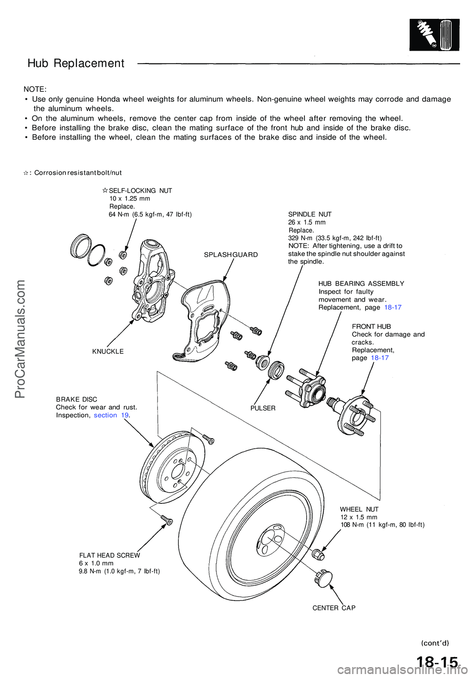
Hub Replacemen t
NOTE:
• Us e onl y genuin e Hond a whee l weight s fo r aluminu m wheels . Non-genuin e whee l weight s ma y corrod e an d damag e
th e aluminu m wheels .
• O n th e aluminu m wheels , remov e th e cente r ca p fro m insid e o f th e whee l afte r removin g th e wheel .
• Befor e installin g th e brak e disc , clea n th e matin g surfac e o f th e fron t hu b an d insid e o f th e brak e disc .
• Befor e installin g th e wheel , clea n th e matin g surface s o f th e brak e dis c an d insid e o f th e wheel .
HUB BEARIN G ASSEMBLYInspec t fo r fault y
movemen t an d wear .
Replacement , pag e 18-1 7
BRAK E DIS CChec k fo r wea r an d rust .
Inspection , sectio n 19 . FRON
T HU B
Chec k fo r damag e an d
cracks .Replacement ,
pag e 18-1 7
WHEE L NU T12 x 1. 5 m m108 N- m (1 1 kgf-m , 8 0 Ibf-ft )
FLAT HEA D SCRE W6 x 1. 0 m m9.8 N- m (1. 0 kgf-m , 7 Ibf-ft )
CENTE R CA P
SPLAS H GUAR D
PULSE R
KNUCKL E
Corrosion resistan t bolt/nu t
SELF-LOCKIN G NU T10 x 1.2 5 mmReplace .64 N- m (6. 5 kgf-m , 4 7 Ibf-ft )SPINDL E NU T26 x 1. 5 m mReplace .329 N- m (33. 5 kgf-m , 24 2 Ibf-ft )NOTE : Afte r tightening , us e a drif t t o
stak e th e spindl e nu t shoulde r agains t
th e spindle .
ProCarManuals.com
Page 962 of 1503
Reassembly
1. Install the damper unit on a spring compressor.
2. Assemble the damper in reverse order of removal
except the damper mounting washer and self-locking
nut.
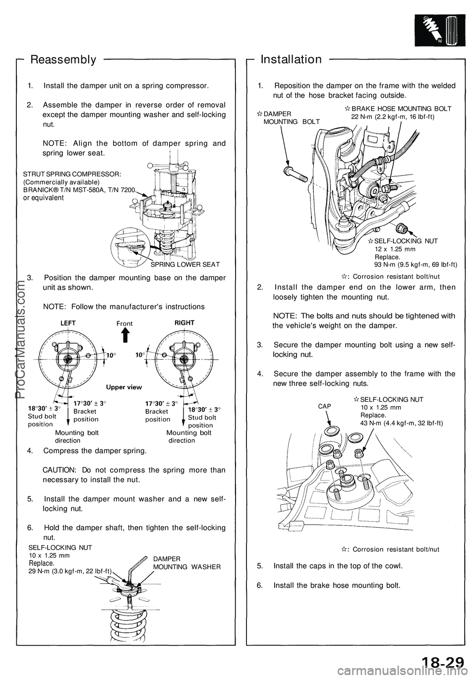
NOTE: Align the bottom of damper spring and
spring lower seat.
STRUT SPRING COMPRESSOR:
(Commercially available)
BRANICK® T/N MST-580A, T/N 7200.
or equivalent
SPRING LOWER SEAT
3. Position the damper mounting base on the damper
unit as shown.
NOTE: Follow the manufacturer's instructions
CAUTION: Do not compress the spring more than
necessary to install the nut.
5. Install the damper mount washer and a new self-
locking nut.
6. Hold the damper shaft, then tighten the self-locking
nut.
Installation
1. Reposition the damper on the frame with the welded
nut of the hose bracket facing outside.
DAMPER
MOUNTING BOLT
BRAKE HOSE MOUNTING BOLT
22 N-m (2.2 kgf-m, 16 Ibf-ft)
SELF-LOCKING NUT
12 x
1.25
mm
Replace.
93 N-m (9.5 kgf-m, 69 Ibf-ft)
Corrosion resistant bolt/nut
2. Install the damper end on the lower arm, then
loosely tighten the mounting nut.
NOTE: The bolts and nuts should be tightened with
the vehicle's weight on the damper.
3. Secure the damper mounting bolt using a new self-
locking nut.
4. Secure the damper assembly to the frame with the
new three self-locking nuts.
Corrosion resistant bolt/nut
5. Install the caps in the top of the cowl.
6. Install the brake hose mounting bolt.
Mounting bolt Mounting bolt
direction direction
4. Compress the damper spring.
SELF-LOCKING NUT
10 x
1.25
mm
Replace.
29 N-m (3.0 kgf-m, 22 Ibf-ft)
DAMPER
MOUNTING WASHER
CAP
SELF-LOCKING NUT
10 x
1.25
mm
Replace.
43 N-m (4.4 kgf-m, 32 Ibf-ft)ProCarManuals.com
Page 964 of 1503
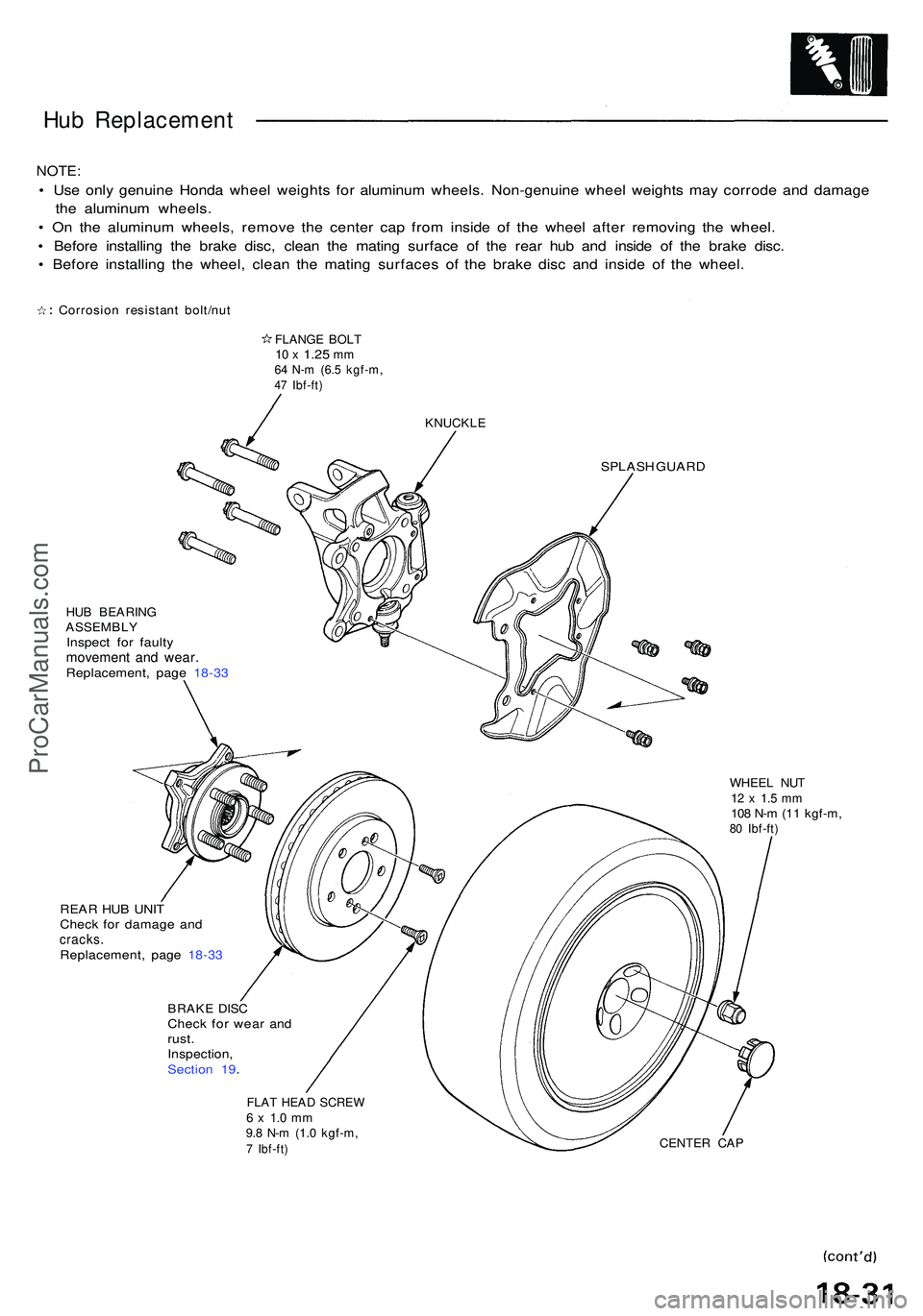
Hub Replacemen t
NOTE:
• Us e onl y genuin e Hond a whee l weight s fo r aluminu m wheels . Non-genuin e whee l weight s ma y corrod e an d damag e
th e aluminu m wheels .
• O n th e aluminu m wheels , remov e th e cente r ca p fro m insid e o f th e whee l afte r removin g th e wheel .
• Befor e installin g th e brak e disc , clea n th e matin g surfac e of the rea r hu b an d insid e of the brak e disc .
• Befor e installin g th e wheel , clea n th e matin g surface s o f th e brak e dis c an d insid e o f th e wheel .
Corrosio n resistan t bolt/nu t
FLANGE BOL T10 x 1.2 5 mm64 N- m (6. 5 kgf-m ,47 Ibf-ft )
KNUCKL E
SPLASH GUAR D
HUB BEARIN GASSEMBL YInspect fo r fault ymovemen t an d wear .Replacement , pag e 18-3 3
WHEE L NU T12 x 1. 5 m m108 N- m (1 1 kgf-m ,80 Ibf-ft )
REAR HU B UNI T
Chec k fo r damag e an d
cracks .Replacement , pag e 18-3 3
BRAK E DIS CChec k fo r wea r an d
rust .
Inspection ,
Sectio n 19 .
FLA T HEA D SCRE W6 x 1. 0 m m9.8 N- m (1. 0 kgf-m ,7 Ibf-ft )CENTE R CA P
ProCarManuals.com