1997 ACURA NSX turn signal
[x] Cancel search: turn signalPage 1351 of 1503
Taillights
Replacement
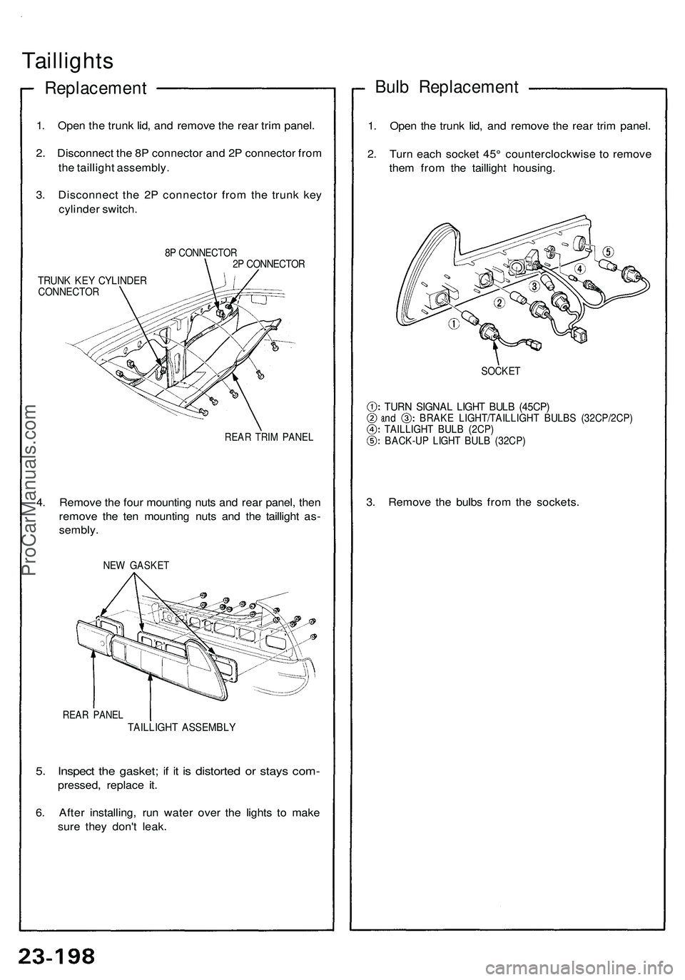
1. Open the trunk lid, and remove the rear trim panel.
2. Disconnect the 8P connector and 2P connector from
the taillight assembly.
3. Disconnect the 2P connector from the trunk key
cylinder switch.
8P CONNECTOR
2P CONNECTOR
TRUNK KEY CYLINDER
CONNECTOR
REAR TRIM PANEL
4. Remove the four mounting nuts and rear panel, then
remove the ten mounting nuts and the taillight as-
sembly.
NEW GASKET
REAR PANEL
TAILLIGHT ASSEMBLY
5. Inspect the gasket; if it is distorted or stays com-
pressed, replace it.
6. After installing, run water over the lights to make
sure they don't leak.
Bulb Replacement
1. Open the trunk lid, and remove the rear trim panel.
2. Turn each socket 45° counterclockwise to remove
them from the taillight housing.
SOCKET
TURN SIGNAL LIGHT BULB (45CP)
and BRAKE LIGHT/TAILLIGHT BULBS (32CP/2CP)
TAILLIGHT BULB (2CP)
BACK-UP LIGHT BULB (32CP)
3. Remove the bulbs from the sockets.ProCarManuals.com
Page 1366 of 1503
Side Marker/Turn Signal/Hazard Flasher System
Description
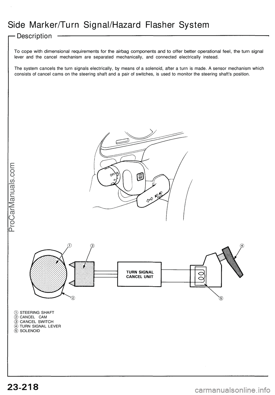
To cope with dimensional requirements for the airbag components and to offer better operational feel, the turn signal
lever and the cancel mechanism are separated mechanically, and connected electrically instead.
The system cancels the turn signals electrically, by means of a solenoid, after a turn is made. A sensor mechanism which
consists of cancel cams on the steering shaft and a pair of switches, is used to monitor the steering shaft's position.
STEERING SHAFT
CANCEL CAM
CANCEL SWITCH
TURN SIGNAL LEVER
SOLENOIDProCarManuals.com
Page 1367 of 1503
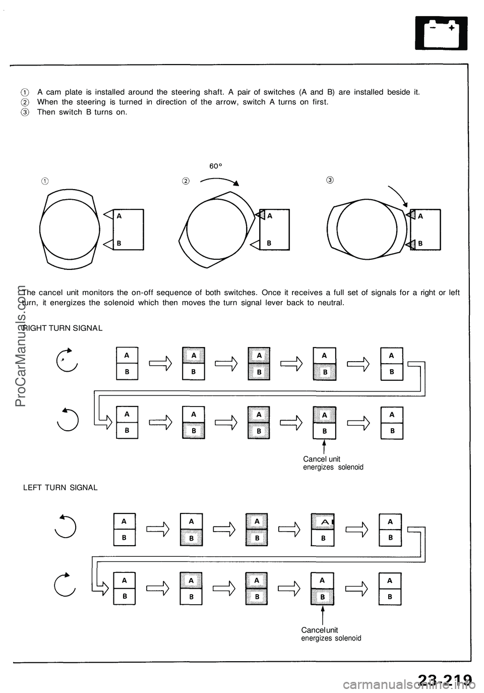
A cam plate is installed around the steering shaft. A pair of switches (A and B) are installed beside it.
When the steering is turned in direction of the arrow, switch A turns on first.
Then switch B turns on.
The cancel unit monitors the on-off sequence of both switches. Once it receives a full set of signals for a right or left
turn, it energizes the solenoid which then moves the turn signal lever back to neutral.
RIGHT TURN SIGNAL
LEFT TURN SIGNAL
Cancel unit
energizes solenoid
A
I
Cancel unit
energizes solenoidProCarManuals.com
Page 1368 of 1503
Side Marker/Turn Signal/Hazard Flasher System
Turn Signal/Hazard Relay Input Test
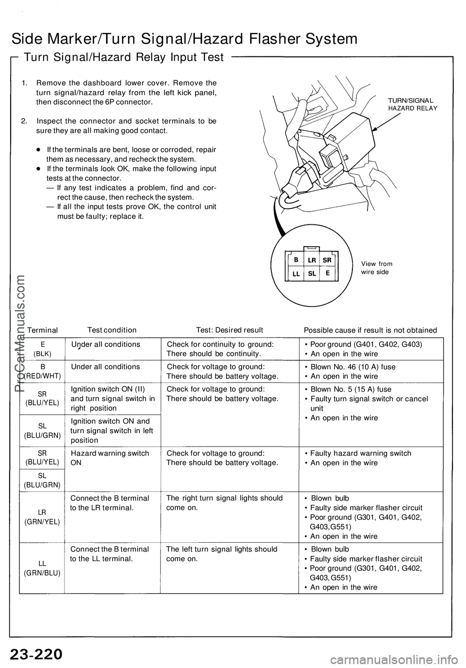
1. Remove the dashboard lower cover. Remove the
turn signal/hazard relay from the left kick panel,
then disconnect the 6P connector.
2. Inspect the connector and socket terminals to be
sure they are all making good contact.
If the terminals are bent, loose or corroded, repair
them as necessary, and recheck the system.
If the terminals look OK, make the following input
tests at the connector.
— If any test indicates a problem, find and cor-
rect the cause, then recheck the system.
— If all the input tests prove OK, the control unit
must be faulty; replace it.
TURN/SIGNAL
HAZARD RELAY
View from
wire side
Terminal
Test condition
Test: Desired result
Possible cause if result is not obtained
E
(BLK)
Under all conditions
Check for continuity to ground:
There should be continuity.
• Poor ground (G401, G402, G403)
• An open in the wire
B
(RED/WHT)
Under all conditions
Check for voltage to ground:
There should be battery voltage.
• Blown No. 46 (10 A) fuse
• An open in the wire
SR
(BLU/YEL)
Ignition switch ON (II)
and turn signal switch in
right position
Check for voltage to ground:
There should be battery voltage.
SL
(BLU/GRN)
Ignition switch ON and
turn signal switch in left
position
• Blown No. 5 (15 A) fuse
• Faulty turn signal switch or cancel
unit
• An open in the wire
SR
(BLU/YEL)
Hazard warning switch
ON
Check for voltage to ground:
There should be battery voltage.
SL
(BLU/GRN)
LR
(GRN/YEL)
Connect the B terminal
to the LR terminal.
The right turn signal lights should
come on.
• Blown bulb
• Faulty side marker flasher circuit
• Poor ground (G301, G401, G402,
G403, G551)
• An open in the wire
LL
(GRN/BLU)
Connect the B terminal
to the LL terminal.
The left turn signal lights should
come on.
• Blown bulb
• Faulty side marker flasher circuit
• Poor ground (G301, G401, G402,
G403, G551)
• An open in the wire
• Faulty hazard warning switch
• An open in the wireProCarManuals.com
Page 1369 of 1503
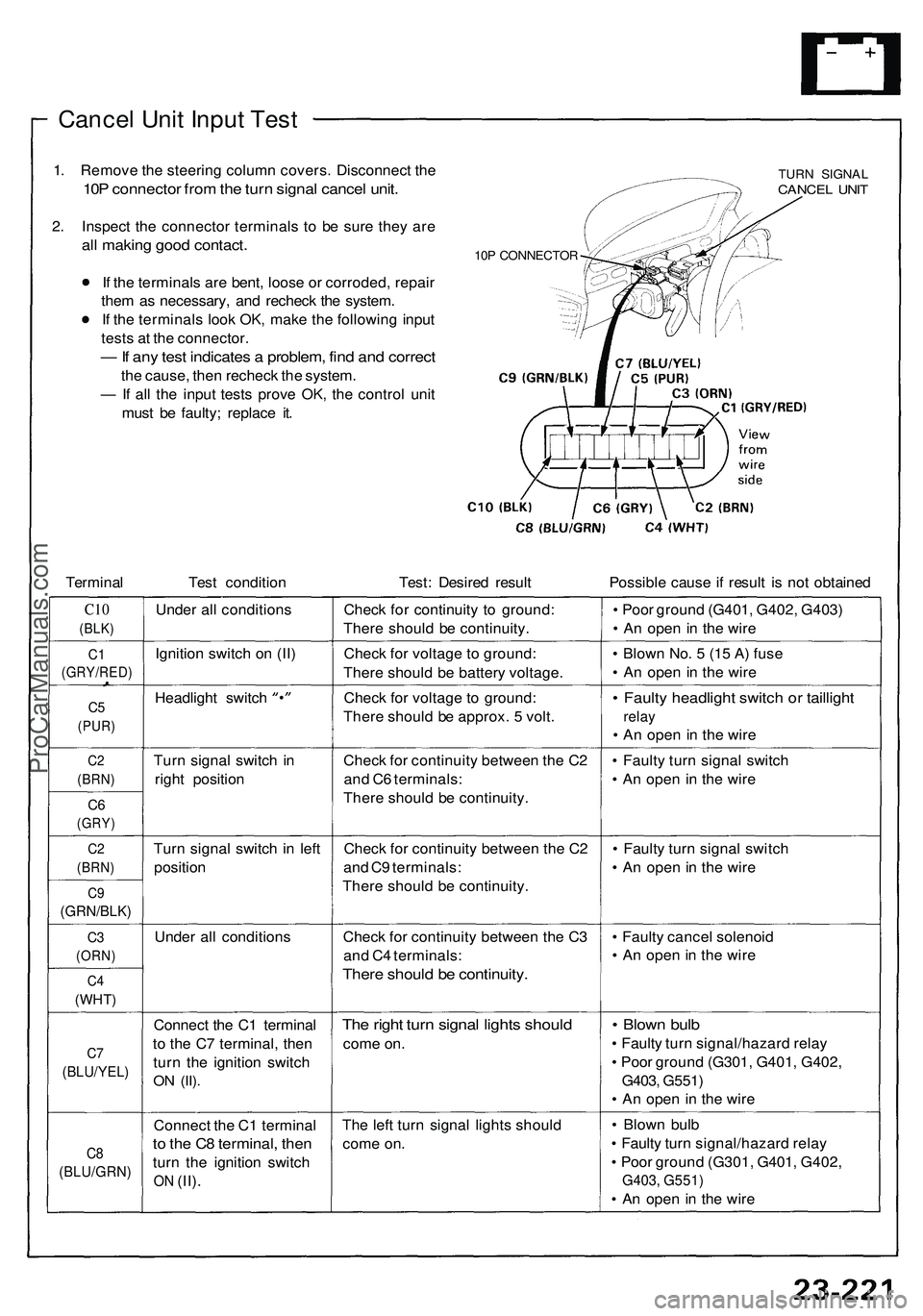
Cancel Unit Input Test
1. Remove the steering column covers. Disconnect the
10P connector from the turn signal cancel unit.
2. Inspect the connector terminals to be sure they are
all making good contact.
If the terminals are bent, loose or corroded, repair
them as necessary, and recheck the system.
If the terminals look OK, make the following input
tests at the connector.
— If any test indicates a problem, find and correct
the cause, then recheck the system.
— If all the input tests prove OK, the control unit
must be faulty; replace it.
10P CONNECTOR
TURN SIGNAL
CANCEL UNIT
Terminal
Test condition
Test: Desired result
Possible cause if result is not obtained
C10
(BLK)
Under all conditions
Check for continuity to ground:
There should be continuity.
• Poor ground (G401, G402, G403)
• An open in the wire
C1
(GRY/RED)
Ignition switch on (II)
Check for voltage to ground:
There should be battery voltage.
• Blown No. 5 (15 A) fuse
• An open in the wire
C5
(PUR)
Headlight switch
Check for voltage to ground:
There should be approx. 5 volt.
• Faulty headlight switch or taillight
relay
• An open in the wire
C2
(BRN)
Turn signal switch in
right position
C6
(GRY)
Check for continuity between the C2
and C6 terminals:
There should be continuity.
• Faulty turn signal switch
• An open in the wire
C2
(BRN)
Turn signal switch in left
position
C9
(GRN/BLK)
Check for continuity between the C2
and C9 terminals:
There should be continuity.
• Faulty turn signal switch
• An open in the wire
C3
(ORN)
Under all conditions
C4
(WHT)
Check for continuity between the C3
and C4 terminals:
There should be continuity.
• Faulty cancel solenoid
• An open in the wire
C7
(BLU/YEL)
Connect the C1 terminal
to the C7 terminal, then
turn the ignition switch
ON
(II).
The right turn signal lights should
come on.
• Blown bulb
• Faulty turn signal/hazard relay
• Poor ground (G301, G401, G402,
G403, G551)
• An open in the wire
C8
(BLU/GRN)
Connect the C1 terminal
to the C8 terminal, then
turn the ignition switch
ON
(II).
The left turn signal lights should
come on.
• Blown bulb
• Faulty turn signal/hazard relay
• Poor ground (G301, G401, G402,
G403, G551)
• An open in the wireProCarManuals.com
Page 1442 of 1503
Cruise Contro l
Descriptio n
The cruis e contro l syste m use s mechanicall y an d electri -
call y operate d device s t o maintai n vehicl e spee d a t a
settin g selecte d b y th e driver .
Th e EC M receive s comman d signals from th e cruis e con -
trol mai n switc h an d th e cruis e contro l set/resum e switch.
I t receive s informatio n abou t operatin g condition s fro m
th e brak e switch , vehicl e spee d senso r (VSS) , th e clutc h
switch (wit h manua l transmission) , o r th e A/ T gea r posi -
tio n switc h (wit h automati c transmission) . Th e EC M
send s operationa l signal s t o th e device s tha t regulat e th e
throttl e position . Th e throttl e positio n maintain s th e
selecte d vehicl e speed . Essentially , th e EC M compare s
th e actua l spee d of the vehicl e t o th e selecte d speed .
Then , i t use s th e resul t of tha t compariso n t o ope n o r
clos e th e throttle .
Th e brak e switc h release s th e system' s contro l o f th e
throttl e a t th e instan t th e drive r depresse s th e brak e
pedal . Th e switc h send s a n electroni c signa l t o th e EC M
whe n th e brak e peda l i s depressed ; th e EC M respond s
b y allowin g th e throttl e t o close . Th e clutc h switc h (man -
ual transmission ) o r th e A/ T gea r positio n switc h (auto -
mati c transmission ) send s a disengag e signa l t o th e
EC M tha t als o allow s th e throttl e t o close . Operation
:
Th e cruis e contro l syste m wil l se t an d automaticall y
maintai n an y spee d abov e 2 5 mp h (4 5 km/h) . T o set ,
mak e sur e tha t th e mai n switc h i s i n th e "ON " position .
Afte r reachin g th e desire d speed , pres s th e se t switch .
Th e EC M wil l receiv e a se t signa l and , i n turn , wil l actu -
at e th e throttl e valv e contro l motor . Whe n th e se t switc h
i s depresse d an d th e cruis e contro l syste m is on , th e
"cruis e control " O N indicato r i n th e gaug e assembl y wil l
ligh t up . Yo u ca n cance l th e cruis e contro l syste m b y
pushin g th e mai n switc h t o "OFF" . Thi s erase s th e se t
spee d fro m memory . I f th e syste m is disengage d tem -
poraril y b y th e brak e switch , clutc h switch , o r A/ T gea r
positio n switc h an d vehicl e spee d i s stil l abov e 2 5 mph ,
pres s th e resum e switch . Wit h th e resum e switc h
depresse d an d th e se t memor y retained , th e vehicl e
automaticall y return s t o th e previou s se t speed .
Fo r gradua l acceleratio n withou t depressin g th e acceler -
ato r pedal , pus h th e resum e switc h dow n an d hol d i t
ther e unti l th e desire d spee d i s reached . Thi s wil l sen d
a n acceleratio n signa l t o th e ECM . Whe n th e switc h i s
released , th e syste m wil l b e reprogramme d fo r th e ne w
speed . T o slo w down , depres s th e se t switch . Thi s wil l
sen d a deceleratio n signa l t o th e EC M causin g th e ca r t o
coas t unti l th e desire d spee d i s reached . Whe n th e
desire d spee d i s reached , releas e th e se t switch . Thi s
wil l reprogra m th e syste m fo r th e ne w speed .
ProCarManuals.com
Page 1466 of 1503
Immobilizer Syste m
Descriptio n
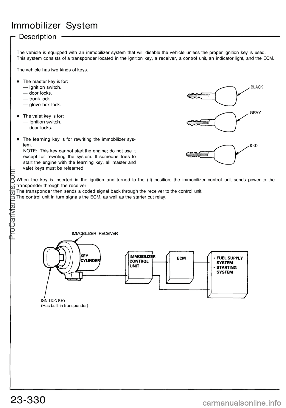
The vehicl e i s equippe d wit h a n immobilize r syste m tha t wil l disabl e th e vehicl e unles s th e prope r ignitio n ke y i s used .
Thi s syste m consist s o f a transponde r locate d i n th e ignitio n key , a receiver , a contro l unit , a n indicato r light , an d th e ECM .
Th e vehicl e ha s tw o kind s o f keys .
BLAC K
GRAY
The maste r ke y i s for :
— ignitio n switch .
— doo r locks .
— trun k lock .
— glov e bo x lock .
Th e vale t ke y i s for :
— ignitio n switch .
— doo r locks .
Th e learnin g ke y i s fo r rewritin g th e immobilize r sys -
tem.
NOTE : Thi s ke y canno t star t th e engine ; d o no t us e i t
excep t fo r rewritin g th e system . I f someon e trie s t o
star t th e engin e wit h th e learnin g key , al l maste r an d
vale t key s mus t b e relearned .
Whe n th e ke y i s inserte d i n th e ignitio n an d turne d t o th e (II ) position , th e immobilize r contro l uni t send s powe r t o th e
transponde r throug h th e receiver .
Th e transponde r the n send s a code d signa l bac k throug h th e receive r t o th e contro l unit .
Th e contro l uni t i n tur n signal s th e ECM , a s wel l a s th e starte r cu t relay .
RED
IMMOBILIZE R RECEIVE R
IGNITION KE Y(Has built-i n transponder )
23-330ProCarManuals.com
Page 1467 of 1503
IGNITION SWITCH
PROPER KEY
INSERTED
INDICATOR
LIGHT
WRONG KEY
INSERTED
INDICATOR
LIGHT
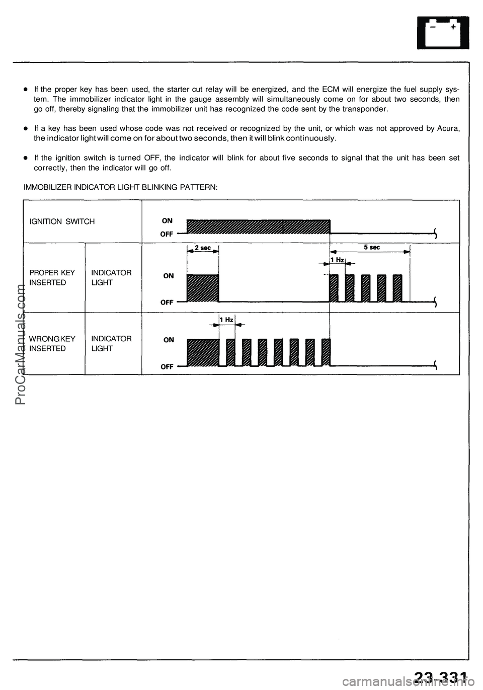
If the proper key has been used, the starter cut relay will be energized, and the ECM will energize the fuel supply sys-
tem. The immobilizer indicator light in the gauge assembly will simultaneously come on for about two seconds, then
go off, thereby signaling that the immobilizer unit has recognized the code sent by the transponder.
If a key has been used whose code was not received or recognized by the unit, or which was not approved by Acura,
the indicator light will come on for about two seconds, then it will blink continuously.
If the ignition switch is turned OFF, the indicator will blink for about five seconds to signal that the unit has been set
correctly, then the indicator will go off.
IMMOBILIZER INDICATOR LIGHT BLINKING PATTERN:ProCarManuals.com