1997 ACURA NSX turn signal
[x] Cancel search: turn signalPage 726 of 1503
Electronic Control System (cont'd)
Description
• Automatic shifting control in Sport Shifting mode
This position also has automatic shifting areas:
• 1-2 upshift
• 4-3 downshift, 3-1 downshift, 2-1 downshift
depending on vehicle speed. To prevent engine over-revving, the transmission has a 1-2 automatic upshift speed, and 4-3,
3-1, 2-1 downshift allowable speeds.
• When the vehicle reaches the 1-2 automatic upshift speed, the TCM outputs the 1-2 upshift signal to the transmis-
sion and the transmission upshifts to 2nd from 1st gear.
• When the vehicle is coasting over the 4-3 downshift allowable speed and 3-2 downshift allowable speed, the TCM
does not input the downshift signal from the shift switch, and the transmission does not downshift.
• When the vehicle is coasting over the 2-1 downshift allowable speed in 2nd gear, the TCM inputs the signal to wait
until it reaches the 2-1 downshift allowable speed, then the shift indicator blinks to indicate it is waiting to downshift
to
1st.
When the vehicle decelerates to a stop, the transmission shifts to 1st gear automatically.
The transmission can be shifted to 2nd gear by pushing the shift switch up while the vehicle is stopped. This allows the
vehicle to start off in 2nd gear.
Lock-up Control
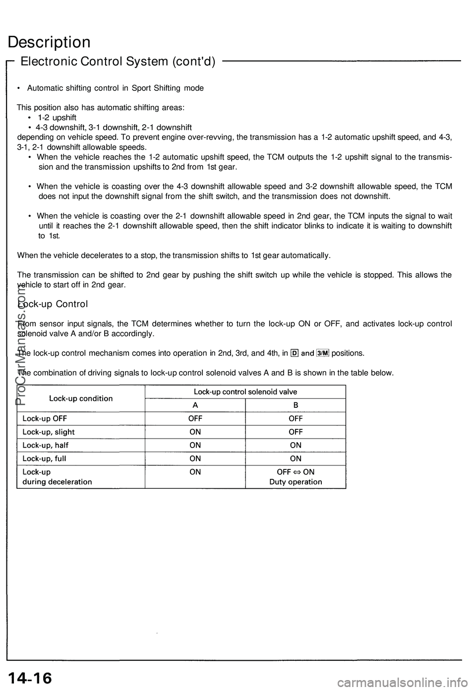
From sensor input signals, the TCM determines whether to turn the lock-up ON or OFF, and activates lock-up control
solenoid valve A and/or B accordingly.
The lock-up control mechanism comes into operation in 2nd, 3rd, and 4th, in positions.
The combination of driving signals to lock-up control solenoid valves A and B is shown in the table below.ProCarManuals.com
Page 745 of 1503
Position
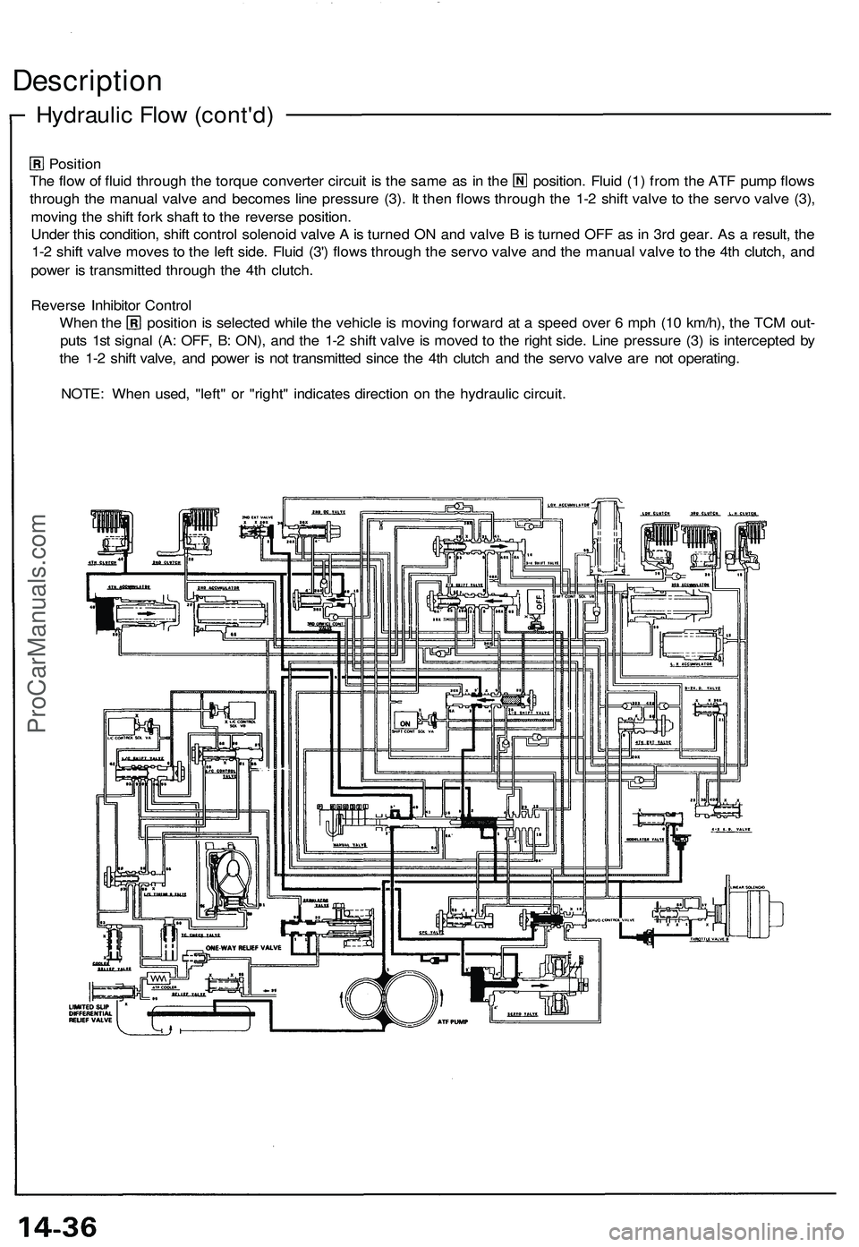
The flow of fluid through the torque converter circuit is the same as in the position. Fluid (1) from the ATF pump flows
through the manual valve and becomes line pressure (3). It then flows through the 1-2 shift valve to the servo valve (3),
moving the shift fork shaft to the reverse position.
Under this condition, shift control solenoid valve A is turned ON and valve B is turned OFF as in 3rd gear. As a result, the
1-2 shift valve moves to the left side. Fluid (3') flows through the servo valve and the manual valve to the 4th clutch, and
power is transmitted through the 4th clutch.
Reverse Inhibitor Control
When the position is selected while the vehicle is moving forward at a speed over 6 mph (10 km/h), the TCM out-
puts 1st signal (A: OFF, B: ON), and the 1-2 shift valve is moved to the right side. Line pressure (3) is intercepted by
the 1-2 shift valve, and power is not transmitted since the 4th clutch and the servo valve are not operating.
NOTE: When used, "left" or "right" indicates direction on the hydraulic circuit.
Hydraulic Flow (cont'd)
DescriptionProCarManuals.com
Page 899 of 1503
System Description
Function and Operation
Steering Sensor
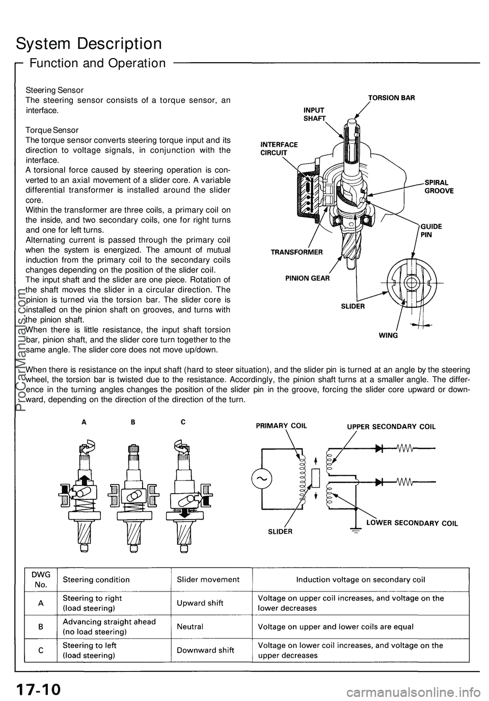
The steering sensor consists of a torque sensor, an
interface.
Torque Sensor
The torque sensor converts steering torque input and its
direction to voltage signals, in conjunction with the
interface.
A torsional force caused by steering operation is con-
verted to an axial movement of a slider core. A variable
differential transformer is installed around the slider
core.
Within the transformer are three coils, a primary coil on
the inside, and two secondary coils, one for right turns
and one for left turns.
Alternating current is passed through the primary coil
when the system is energized. The amount of mutual
induction from the primary coil to the secondary coils
changes depending on the position of the slider coil.
The input shaft and the slider are one piece. Rotation of
the shaft moves the slider in a circular direction. The
pinion is turned via the torsion bar. The slider core is
installed on the pinion shaft on grooves, and turns with
the pinion shaft.
When there is little resistance, the input shaft torsion
bar, pinion shaft, and the slider core turn together to the
same angle. The slider core does not move up/down.
When there is resistance on the input shaft (hard to steer situation), and the slider pin is turned at an angle by the steering
wheel, the torsion bar is twisted due to the resistance. Accordingly, the pinion shaft turns at a smaller angle. The differ-
ence in the turning angles changes the position of the slider pin in the groove, forcing the slider core upward or down-
ward, depending on the direction of the direction of the turn.ProCarManuals.com
Page 901 of 1503
System Description
Function and Operation (cont'd)
EPS Control Unit
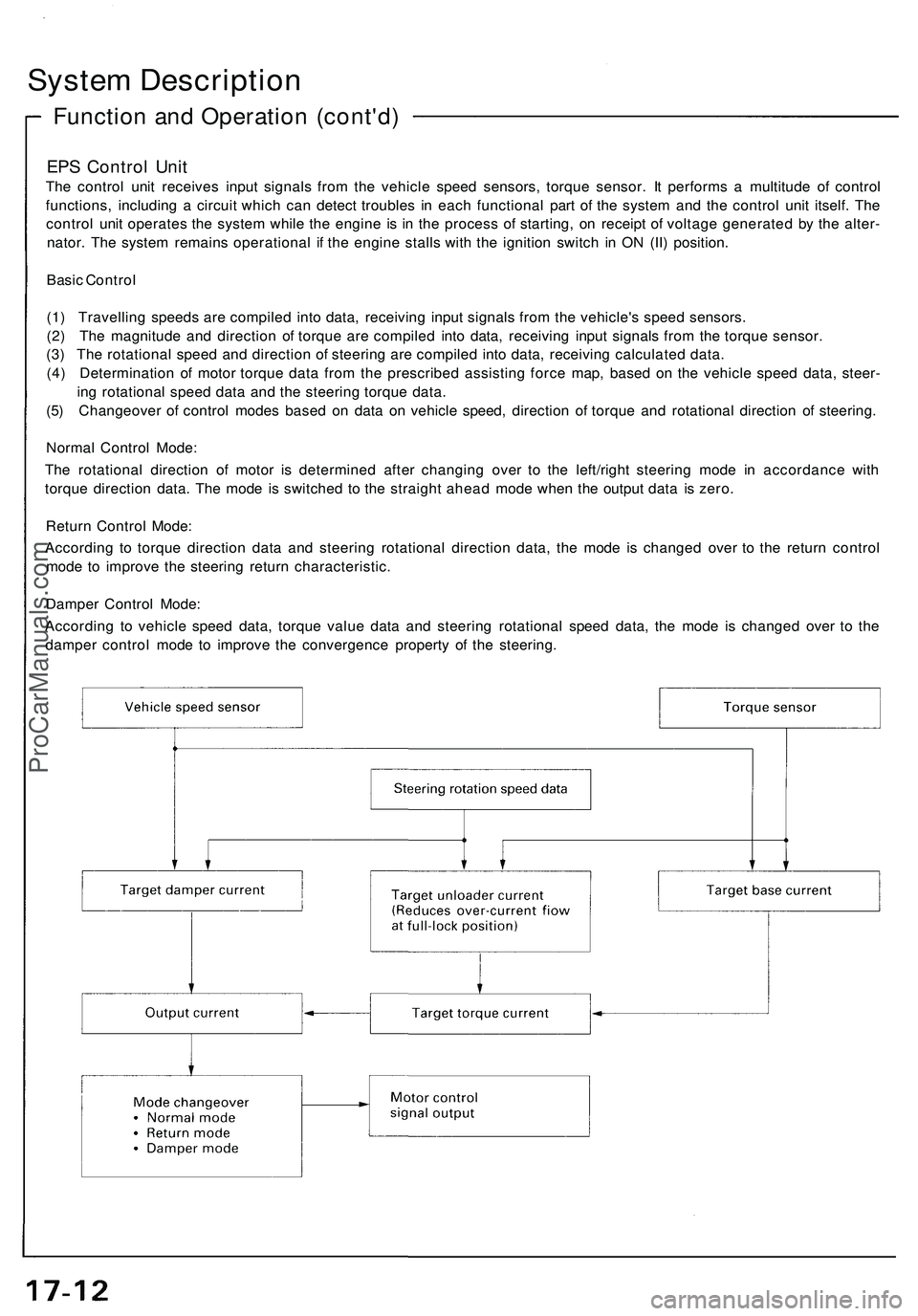
The control unit receives input signals from the vehicle speed sensors, torque sensor. It performs a multitude of control
functions, including a circuit which can detect troubles in each functional part of the system and the control unit itself. The
control unit operates the system while the engine is in the process of starting, on receipt of voltage generated by the alter-
nator. The system remains operational if the engine stalls with the ignition switch in ON (II) position.
Basic Control
(1) Travelling speeds are compiled into data, receiving input signals from the vehicle's speed sensors.
(2) The magnitude and direction of torque are compiled into data, receiving input signals from the torque sensor.
(3) The rotational speed and direction of steering are compiled into data, receiving calculated data.
(4) Determination of motor torque data from the prescribed assisting force map, based on the vehicle speed data, steer-
ing rotational speed data and the steering torque data.
(5) Changeover of control modes based on data on vehicle speed, direction of torque and rotational direction of steering.
Normal Control Mode:
The rotational direction of motor is determined after changing over to the left/right steering mode in accordance with
torque direction data. The mode is switched to the straight ahead mode when the output data is zero.
Return Control Mode:
According to torque direction data and steering rotational direction data, the mode is changed over to the return control
mode to improve the steering return characteristic.
Damper Control Mode:
According to vehicle speed data, torque value data and steering rotational speed data, the mode is changed over to the
damper control mode to improve the convergence property of the steering.ProCarManuals.com
Page 903 of 1503
System Description
Function and Operation (cont'd)
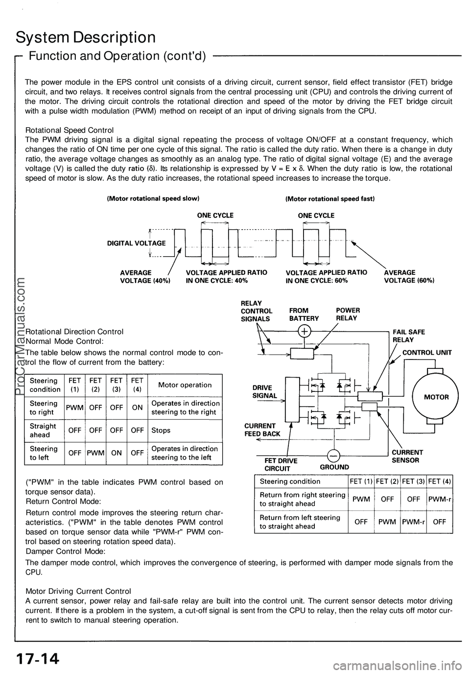
The power module in the EPS control unit consists of a driving circuit, current sensor, field effect transistor (FET) bridge
circuit, and two relays. It receives control signals from the central processing unit (CPU) and controls the driving current of
the motor. The driving circuit controls the rotational direction and speed of the motor by driving the FET bridge circuit
with a pulse width modulation (PWM) method on receipt of an input of driving signals from the CPU.
Rotational Speed Control
The PWM driving signal is a digital signal repeating the process of voltage ON/OFF at a constant frequency, which
changes the ratio of ON time per one cycle of this signal. The ratio is called the duty ratio. When there is a change in duty
ratio, the average voltage changes as smoothly as an analog type. The ratio of digital signal voltage (E) and the average
voltage (V) is called the duty Its relationship is expressed by When the duty ratio is low, the rotational
speed of motor is slow. As the duty ratio increases, the rotational speed increases to increase the torque.
Rotational Direction Control
Normal Mode Control:
The table below shows the normal control mode to con-
trol the flow of current from the battery:
("PWM" in the table indicates PWM control based on
torque sensor data).
Return Control Mode:
Return control mode improves the steering return char-
acteristics. ("PWM" in the table denotes PWM control
based on torque sensor data while "PWM-r" PWM con-
trol based on steering rotation speed data).
Damper Control Mode:
The damper mode control, which improves the convergence of steering, is performed with damper mode signals from the
CPU.
Motor Driving Current Control
A current sensor, power relay and fail-safe relay are built into the control unit. The current sensor detects motor driving
current. If there is a problem in the system, a cut-off signal is sent from the CPU to relay, then the relay cuts off motor cur-
rent to switch to manual steering operation.ProCarManuals.com
Page 1014 of 1503
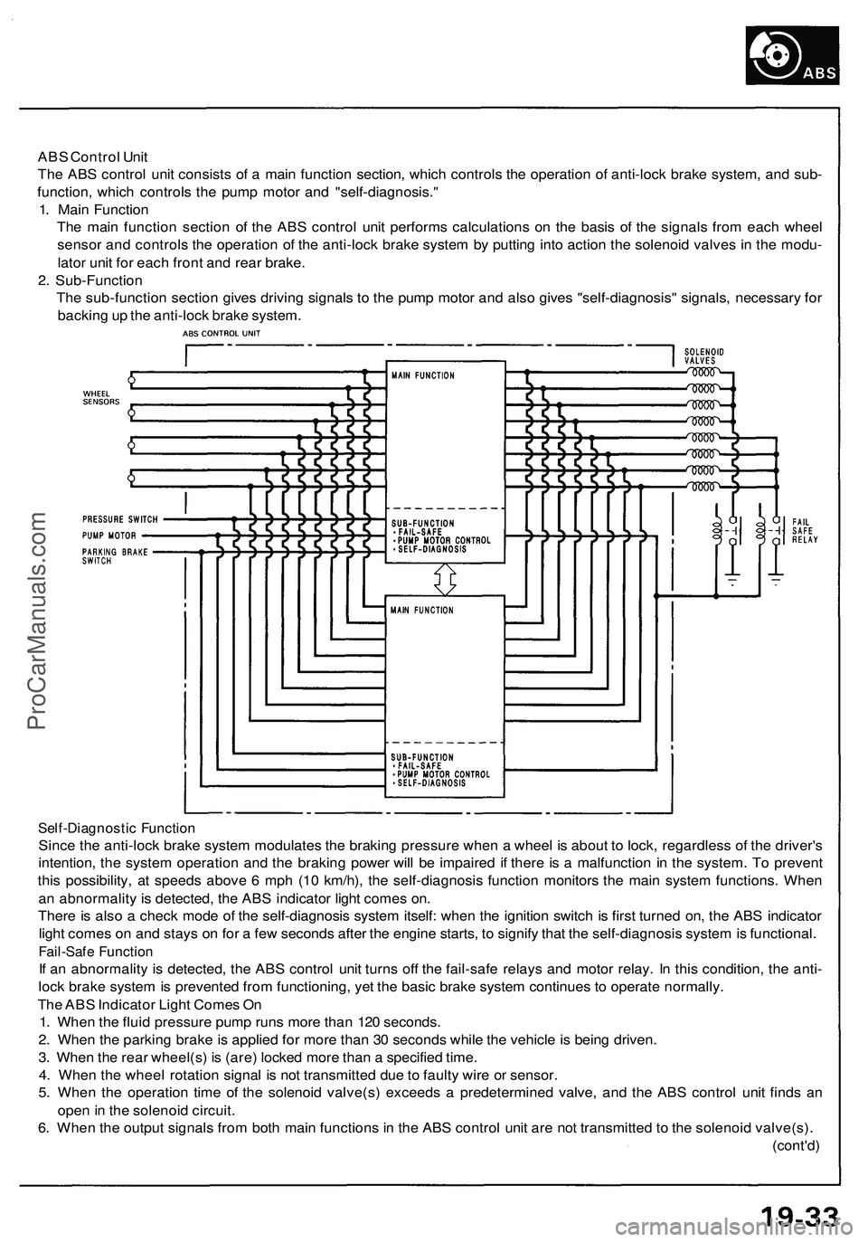
ABS Control Unit
The ABS control unit consists of a main function section, which controls the operation of anti-lock brake system, and sub-
function, which controls the pump motor and "self-diagnosis."
1. Main Function
The main function section of the ABS control unit performs calculations on the basis of the signals from each wheel
sensor and controls the operation of the anti-lock brake system by putting into action the solenoid valves in the modu-
lator unit for each front and rear brake.
2. Sub-Function
The sub-function section gives driving signals to the pump motor and also gives "self-diagnosis" signals, necessary for
backing up the anti-lock brake system.
Self-Diagnostic Function
Since the anti-lock brake system modulates the braking pressure when a wheel is about to lock, regardless of the driver's
intention, the system operation and the braking power will be impaired if there is a malfunction in the system. To prevent
this possibility, at speeds above 6 mph (10 km/h), the self-diagnosis function monitors the main system functions. When
an abnormality is detected, the ABS indicator light comes on.
There is also a check mode of the self-diagnosis system itself: when the ignition switch is first turned on, the ABS indicator
light comes on and stays on for a few seconds after the engine starts, to signify that the self-diagnosis system is functional.
Fail-Safe Function
If an abnormality is detected, the ABS control unit turns off the fail-safe relays and motor relay. In this condition, the anti-
lock brake system is prevented from functioning, yet the basic brake system continues to operate normally.
The ABS Indicator Light Comes On
1. When the fluid pressure pump runs more than 120 seconds.
2. When the parking brake is applied for more than 30 seconds while the vehicle is being driven.
3. When the rear wheel(s) is (are) locked more than a specified time.
4. When the wheel rotation signal is not transmitted due to faulty wire or sensor.
5. When the operation time of the solenoid valve(s) exceeds a predetermined valve, and the ABS control unit finds an
open in the solenoid circuit.
6. When the output signals from both main functions in the ABS control unit are not transmitted to the solenoid valve(s).
(cont'd)ProCarManuals.com
Page 1016 of 1503
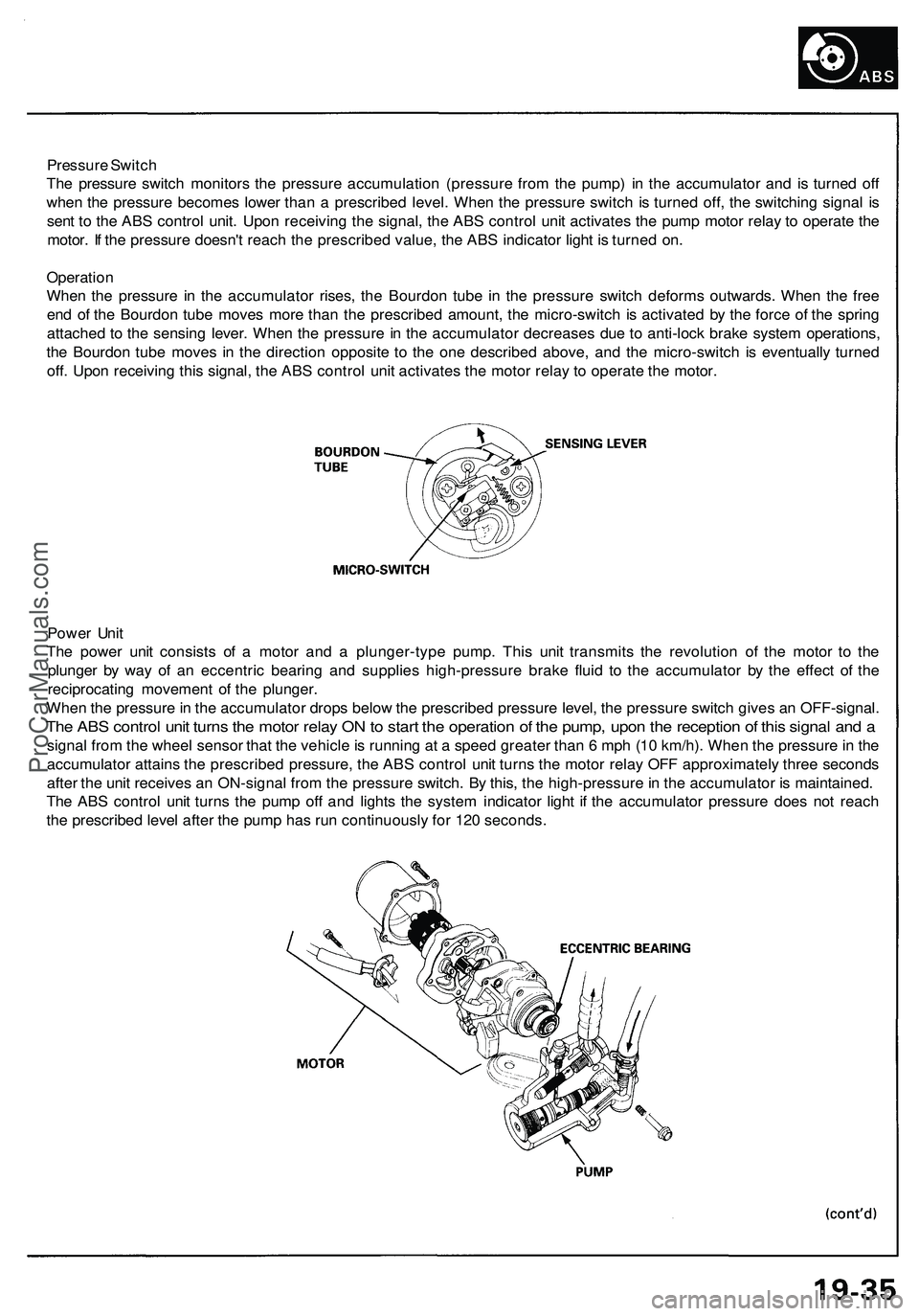
Pressure Switch
The pressure switch monitors the pressure accumulation (pressure from the pump) in the accumulator and is turned off
when the pressure becomes lower than a prescribed level. When the pressure switch is turned off, the switching signal is
sent to the ABS control unit. Upon receiving the signal, the ABS control unit activates the pump motor relay to operate the
motor. If the pressure doesn't reach the prescribed value, the ABS indicator light is turned on.
Operation
When the pressure in the accumulator rises, the Bourdon tube in the pressure switch deforms outwards. When the free
end of the Bourdon tube moves more than the prescribed amount, the micro-switch is activated by the force of the spring
attached to the sensing lever. When the pressure in the accumulator decreases due to anti-lock brake system operations,
the Bourdon tube moves in the direction opposite to the one described above, and the micro-switch is eventually turned
off. Upon receiving this signal, the ABS control unit activates the motor relay to operate the motor.
Power Unit
The power unit consists of a motor and a plunger-type pump. This unit transmits the revolution of the motor to the
plunger by way of an eccentric bearing and supplies high-pressure brake fluid to the accumulator by the effect of the
reciprocating movement of the plunger.
When the pressure in the accumulator drops below the prescribed pressure level, the pressure switch gives an OFF-signal.
The ABS control unit turns the motor relay ON to start the operation of the pump, upon the reception of this signal and a
signal from the wheel sensor that the vehicle is running at a speed greater than 6 mph (10 km/h). When the pressure in the
accumulator attains the prescribed pressure, the ABS control unit turns the motor relay OFF approximately three seconds
after the unit receives an ON-signal from the pressure switch. By this, the high-pressure in the accumulator is maintained.
The ABS control unit turns the pump off and lights the system indicator light if the accumulator pressure does not reach
the prescribed level after the pump has run continuously for 120 seconds.ProCarManuals.com
Page 1046 of 1503
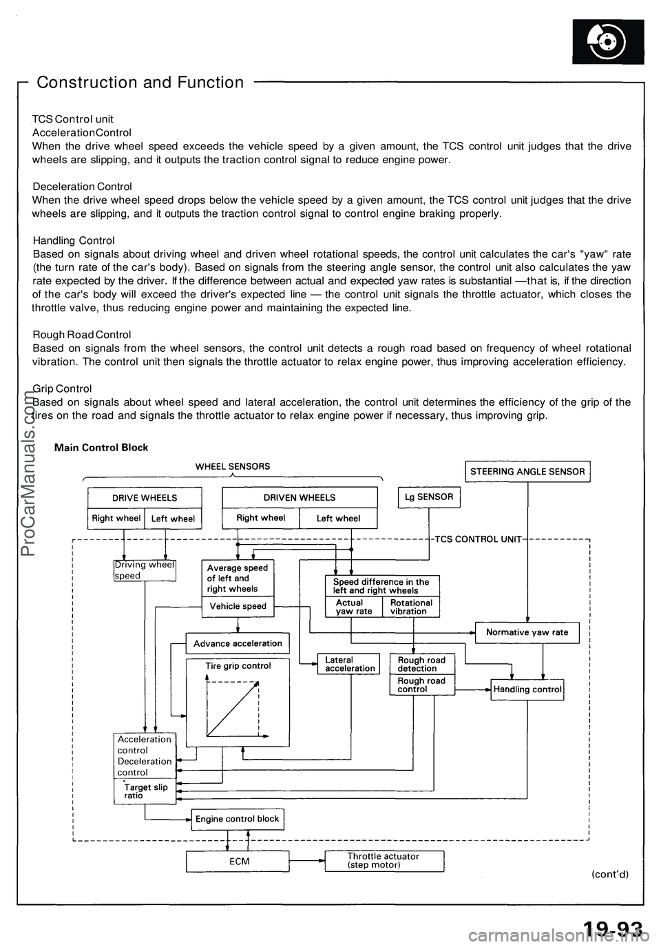
Construction and Function
TCS Control unit
Acceleration Control
When the drive wheel speed exceeds the vehicle speed by a given amount, the TCS control unit judges that the drive
wheels are slipping, and it outputs the traction control signal to reduce engine power.
Deceleration Control
When the drive wheel speed drops below the vehicle speed by a given amount, the TCS control unit judges that the drive
wheels are slipping, and it outputs the traction control signal to control engine braking properly.
Handling Control
Based on signals about driving wheel and driven wheel rotational speeds, the control unit calculates the car's "yaw" rate
(the turn rate of the car's body). Based on signals from the steering angle sensor, the control unit also calculates the yaw
rate expected by the driver. If the difference between actual and expected yaw rates is substantial —that is, if the direction
of the car's body will exceed the driver's expected line — the control unit signals the throttle actuator, which closes the
throttle valve, thus reducing engine power and maintaining the expected line.
Rough Road Control
Based on signals from the wheel sensors, the control unit detects a rough road based on frequency of wheel rotational
vibration. The control unit then signals the throttle actuator to relax engine power, thus improving acceleration efficiency.
Grip Control
Based on signals about wheel speed and lateral acceleration, the control unit determines the efficiency of the grip of the
tires on the road and signals the throttle actuator to relax engine power if necessary, thus improving grip.ProCarManuals.com