Page 1047 of 1503

Construction and Function (cont'd)
System Description
Fail-Safe Function
If the control unit detects an abnormality, it shuts the
traction control system off and causes the TCS indicator
light to come on. However if the abnormality is detected
while the TCS is activated, the control unit first estab-
lishes the appropriate wheel spin velocity, then shuts
the system down, thus preventing excessive wheel spin.
Self-Diagnosis Function
If the control unit detects an abnormality, it records a
Diagnostic Trouble Code (DTC) which can be used to
diagnose the problem. The DTC is shown at the TCS
indicator light when the Service Check connector termi-
nals are connected with the SCS service connector.
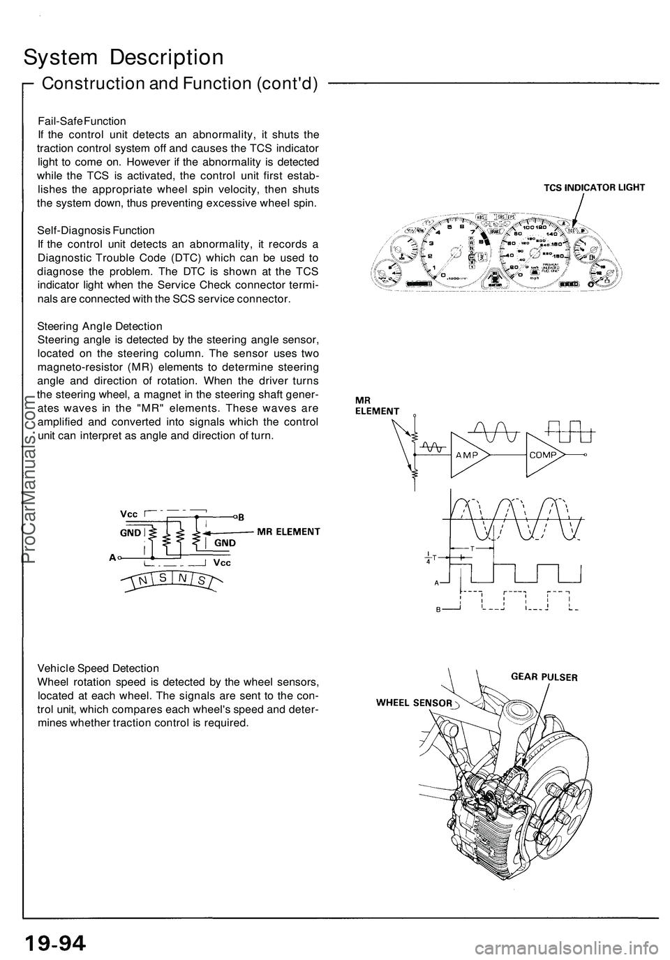
Steering Angle Detection
Steering angle is detected by the steering angle sensor,
located on the steering column. The sensor uses two
magneto-resistor (MR) elements to determine steering
angle and direction of rotation. When the driver turns
the steering wheel, a magnet in the steering shaft gener-
ates waves in the "MR" elements. These waves are
amplified and converted into signals which the control
unit can interpret as angle and direction of turn.
Vehicle Speed Detection
Wheel rotation speed is detected by the wheel sensors,
located at each wheel. The signals are sent to the con-
trol unit, which compares each wheel's speed and deter-
mines whether traction control is required.ProCarManuals.com
Page 1117 of 1503
Front Bumper
Replacement
1. Loosen the mounting screw, then pull the right and left front turn signal lights out and disconnect the connectors.
2. Remove the skirt covers, then remove the bumper mounting bolts on each side, and lower skirt mounting bolt.
3. Lower the inner fender, then remove the bumper mounting nuts and the skirt mounting bolts from inside the front
fender on each side.
4. Lift and remove the front bumper.
NOTE:
• Disconnect the washer hose, horn connecters, and ambient sensor connector.
• An assistant is helpful when removing the front bumper.
• Take care not to scratch the front bumper.
5. Installation is the reverse of the removal procedure.
NOTE: Insert the bumper bracket hooks into the bumper bracket holes.ProCarManuals.com
Page 1184 of 1503
Description
Fan Control Unit
The fan control unit performs calculations based on signals from the radiator fan control sensor. It them controls the
operation of radiator fan speed (High-Low), engine compartment fan, condenser fan and A/C compressor.
When engine coolant temperature is above 183°F
(84°C), the fan control unit turns Tr1 ON and
radiator fan runs at low speed.
When engine coolant temperature is above 194°F
(90°C), the fan control unit turns Tr2 ON, and
radiator fan runs at high speed and engine
compartment fan comes on.
When engine coolant temperature is above 266°F
(130°C), the fan control unit turns Tr3 OFF, and
stops the condenser fan. Then it turns Tr4 OFF,
and stops the compressor.
IG2
RADIATOR FAN (Low)
RADIATOR
FAN CONTROL
SENSOR
RADIATOR FAN (High)
ENGINE COMPARTMENT
FAN
CONDENSER FAN
(Right and Left)
ECM
(ACS)
A/C
TRIPLE
PRESSURE
SWITCH
GND
A/C SWITCHProCarManuals.com
Page 1235 of 1503
Relay and Control Unit Locations
Dashboard
IMMOBILIZER CONTROL UNIT
CLIMATE CONTROL UNIT
TURN SIGNAL/HAZARD
RELAY
DASHBOARD
LOWER COVER
INTEGRATED
CONTROL UNIT
UNDER-DASH FUSE BOXProCarManuals.com
Page 1292 of 1503
Gauge Assembly
Bulb Locations
GAUGE LIGHTS (1.4 Wx 2)
SRS INDICATOR LIGHT (1.4 W)
RIGHT TURN SIGNAL INDICATOR LIGHT 11.4 W)
EPS INDICATOR LIGHT (1.4 W)
BRAKE SYSTEM LIGHT (1.4 W)
SEAT BELT REMINDER LIGHT (1.4 W)
IMMOBILIZER INDICATOR
LIGHT (1.4 W)
LOW FUEL INDICATOR
LIGHT (1.4 W)
GAUGE LIGHT
(1.4
W)
TCS INDICATOR LIGHT (1.96 W)
LEFT TURN SIGNAL INDICATOR LIGHT (1.4 W)
ABS
INDICATOR LIGHT (1.4 W)
CHARGING SYSTEM LIGHT (1.4 W)
MALFUNCTION
INDICATOR
LAMP (MIL)
(1.4
W)
CRUISE INDICATOR LIGHT
(1.96
W)
LOW OIL PRESSURE
INDICATOR
LIGHT (1.4 W)
GAUGE LIGHT
.4W)
GAUGE LIGHT
(3.0
W)
GAUGE LIGHT
GAUGE LIGHT HIGH BEAM INDICATOR (3.0 W)
(3.0 W) LIGHT (1.4 W)ProCarManuals.com
Page 1330 of 1503
Switches
The lighting system is controlled by five switches and the turn signal cancel unit.
HEADLIGHT SWITCH
HAZARD WARNING SWITCH
TURN SIGNAL and DIMMER SWITCH
TURN SIGNAL CANCEL SWITCH
TURN SIGNAL CANCEL UNITProCarManuals.com
Page 1336 of 1503
5. Disconnect the 18P and 10P connectors.
CAUTION: Be careful not to damage the SRS wire
harness.
6. Remove the six screws, then remove the headlight-
turn signal switch assembly.
HEADLIGHT SWITCH
10P CONNECTOR
18PXJONNECTOR
TURN SIGNAL SWITCH
7. If necessary, remove the turn signal cancel unit and
cancel switch.
TURN SIGNAL
CANCEL UNIT
TURN SIGNAL
CANCEL SWITCH
8. If necessary, remove the headlight switch bulb.
HEADLIGHT SWITCH
BULB (0.91 W)ProCarManuals.com
Page 1350 of 1503
Front Turn Signal/Front
Parking Lights
Replacement
1. Remove the screw, and pull the light assembly out
of the front bumper.
SCREW
2. Disconnect the 2P connectors from the bulb sock-
ets.
2P CONNECTORS
FRONT PARKING LIGHT
BULB (5W)
BULB
SOCKET
FRONT TURN SIGNAL
LIGHT BULB (45CP)
HOUSING
3. Turn the bulb sockets 45° counterclockwise to re-
move them from the housing.
Front Side Marker
Lights
Replacement
1. Carefully pry the front side marker light out of the
front fender. Be careful not to damage the front side
marker light or the front fender.
PROTECTIVE CLOTH
FRONT SIDE MARKER LIGHT
2. Disconnect the 2P connector from the front side
marker light.
2P CONNECTOR
HOUSING
3. Turn the bulb socket 45° counterclockwise to re-
move it from the housing.
BULB (3CP)ProCarManuals.com