1997 ACURA NSX light
[x] Cancel search: lightPage 1014 of 1503
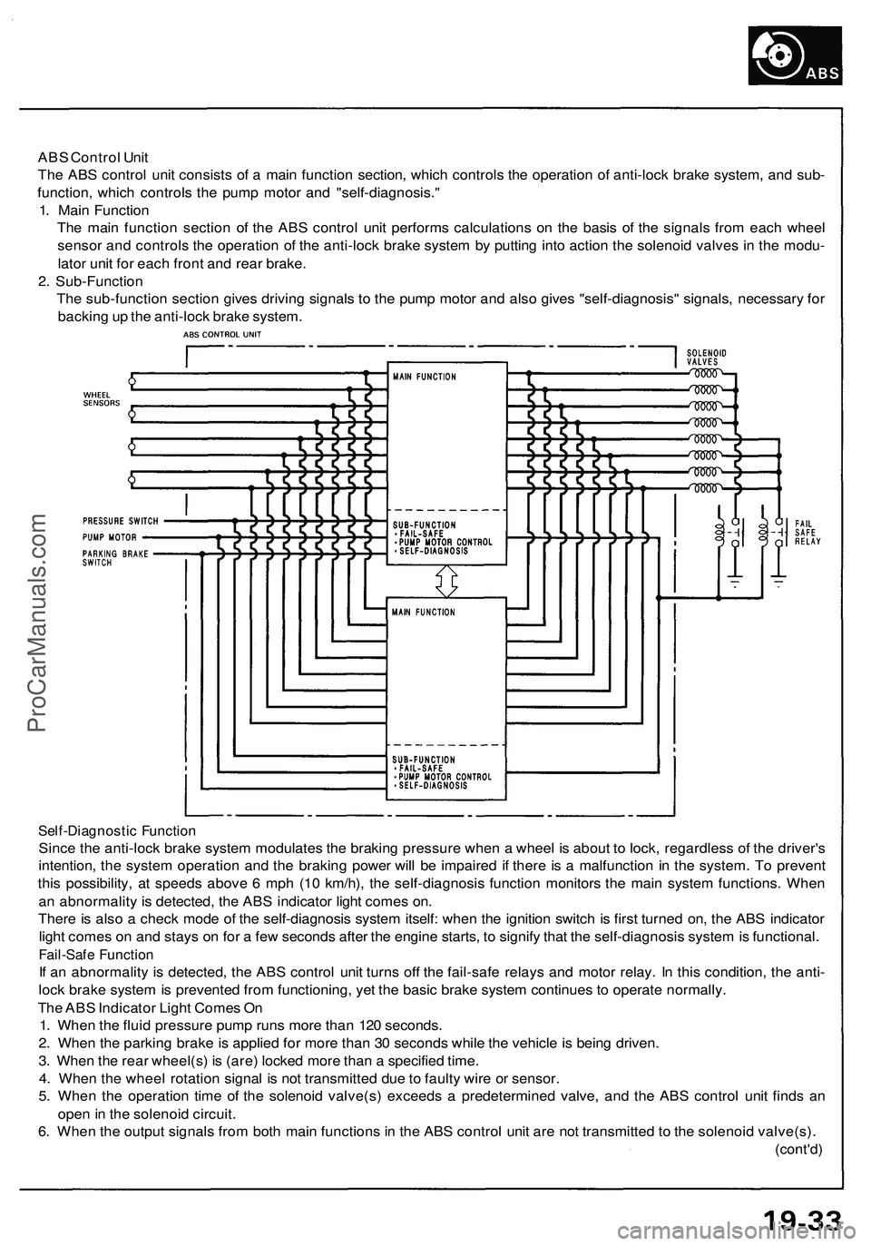
ABS Control Unit
The ABS control unit consists of a main function section, which controls the operation of anti-lock brake system, and sub-
function, which controls the pump motor and "self-diagnosis."
1. Main Function
The main function section of the ABS control unit performs calculations on the basis of the signals from each wheel
sensor and controls the operation of the anti-lock brake system by putting into action the solenoid valves in the modu-
lator unit for each front and rear brake.
2. Sub-Function
The sub-function section gives driving signals to the pump motor and also gives "self-diagnosis" signals, necessary for
backing up the anti-lock brake system.
Self-Diagnostic Function
Since the anti-lock brake system modulates the braking pressure when a wheel is about to lock, regardless of the driver's
intention, the system operation and the braking power will be impaired if there is a malfunction in the system. To prevent
this possibility, at speeds above 6 mph (10 km/h), the self-diagnosis function monitors the main system functions. When
an abnormality is detected, the ABS indicator light comes on.
There is also a check mode of the self-diagnosis system itself: when the ignition switch is first turned on, the ABS indicator
light comes on and stays on for a few seconds after the engine starts, to signify that the self-diagnosis system is functional.
Fail-Safe Function
If an abnormality is detected, the ABS control unit turns off the fail-safe relays and motor relay. In this condition, the anti-
lock brake system is prevented from functioning, yet the basic brake system continues to operate normally.
The ABS Indicator Light Comes On
1. When the fluid pressure pump runs more than 120 seconds.
2. When the parking brake is applied for more than 30 seconds while the vehicle is being driven.
3. When the rear wheel(s) is (are) locked more than a specified time.
4. When the wheel rotation signal is not transmitted due to faulty wire or sensor.
5. When the operation time of the solenoid valve(s) exceeds a predetermined valve, and the ABS control unit finds an
open in the solenoid circuit.
6. When the output signals from both main functions in the ABS control unit are not transmitted to the solenoid valve(s).
(cont'd)ProCarManuals.com
Page 1016 of 1503
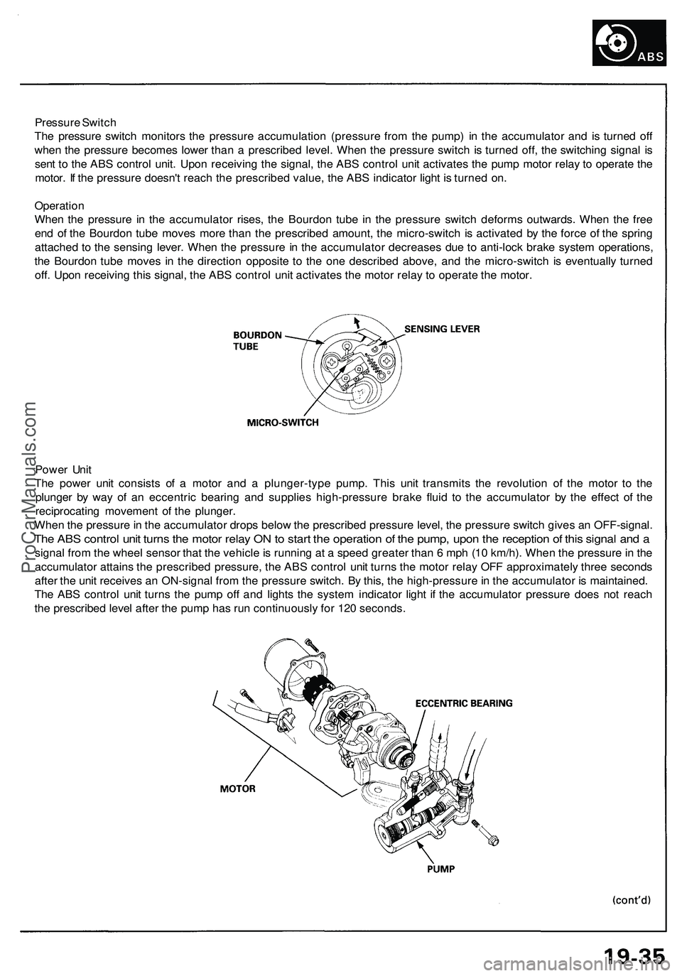
Pressure Switch
The pressure switch monitors the pressure accumulation (pressure from the pump) in the accumulator and is turned off
when the pressure becomes lower than a prescribed level. When the pressure switch is turned off, the switching signal is
sent to the ABS control unit. Upon receiving the signal, the ABS control unit activates the pump motor relay to operate the
motor. If the pressure doesn't reach the prescribed value, the ABS indicator light is turned on.
Operation
When the pressure in the accumulator rises, the Bourdon tube in the pressure switch deforms outwards. When the free
end of the Bourdon tube moves more than the prescribed amount, the micro-switch is activated by the force of the spring
attached to the sensing lever. When the pressure in the accumulator decreases due to anti-lock brake system operations,
the Bourdon tube moves in the direction opposite to the one described above, and the micro-switch is eventually turned
off. Upon receiving this signal, the ABS control unit activates the motor relay to operate the motor.
Power Unit
The power unit consists of a motor and a plunger-type pump. This unit transmits the revolution of the motor to the
plunger by way of an eccentric bearing and supplies high-pressure brake fluid to the accumulator by the effect of the
reciprocating movement of the plunger.
When the pressure in the accumulator drops below the prescribed pressure level, the pressure switch gives an OFF-signal.
The ABS control unit turns the motor relay ON to start the operation of the pump, upon the reception of this signal and a
signal from the wheel sensor that the vehicle is running at a speed greater than 6 mph (10 km/h). When the pressure in the
accumulator attains the prescribed pressure, the ABS control unit turns the motor relay OFF approximately three seconds
after the unit receives an ON-signal from the pressure switch. By this, the high-pressure in the accumulator is maintained.
The ABS control unit turns the pump off and lights the system indicator light if the accumulator pressure does not reach
the prescribed level after the pump has run continuously for 120 seconds.ProCarManuals.com
Page 1025 of 1503
Troubleshooting Precautions
ABS Indicator Light:
The ABS indicator light comes on for three seconds and then goes off when the control unit detects no problem during the
initial diagnosis right after the engine starts. The ABS indicator light comes on, and the ABS control unit memorizes the
diagnostic trouble code (DTC) under certain conditions.
• The parking brake is applied for more than 30 seconds while the vehicle is being driven. (DTC 2-1)
• The vehicle loses traction when starting from a stuck condition on a muddy, snowy, or sandy road. (DTC 4-1, 4-2, 4-4, 4-8)
• The vehicle loses traction, and the front wheels spin for more than one minute when starting from a stuck condition on
a muddy, snowy, or sandy road. (DTC 4-8)
• Tire adhesion is lost due to excessive cornering speed. (DTC 5, 5-4, 5-8)
• The vehicle is interfered by strong radio waves (noise), for example, illegal radio, etc. (DTC 8-2)
NOTE: If there is any trouble in the system, the ABS indicator light comes on during driving.
Diagnostic Trouble Code (DTC):
• When the control unit detects a problem and the ABS indicator light comes on, the control unit memorizes the DTC.
• The control unit has three memory registers. When a problem occurs, the control unit stores the DTC in the first memory
register.
• The most recent DTC is indicated first, and the oldest DTC is indicated last.
• The DTCs are erased from the control unit when the ABS control unit +B2 power supply or connector is disconnected.
• The control unit's memory can be erased by disconnecting the ABS 2, 3 fuse for more than three seconds.
Self-diagnosis:
• There are two self-diagnoses described below.
Initial diagnosis: Performed right after the engine starts until the ABS indicator light goes off.
Regular diagnosis: Continuously performed (under some conditions) after the ABS indicator light goes off until the
engine stops.
• The CPU (central processing unit) controls the following when it detects a problem during self-diagnosis:
Turns the ABS indicator light ON.
Turns the front and rear fail-safe relays off.
Stops the ABS control.
Stops the ABS pump.
After the DTC is stored in the control unit, the CPU stops self-diagnosis.ProCarManuals.com
Page 1026 of 1503
Troubleshooting:
• When two or three DTCs are stored in the control unit, perform troubleshooting for the DTC that appears first.
• When a customer's reported problem cannot be verified on the vehicle, ask the customer about the conditions when
the ABS indicator light came ON, and test-drive the vehicle under those conditions, if possible. When the ABS indicator
light does not come ON during the test, check for loose terminals and check by shaking the harnesses and connectors
while following the flowchart.
• After the repair is completed, perform the ABS function test or test-drive the vehicle, and check that the ABS indicator
light does not come ON again during the test.ProCarManuals.com
Page 1030 of 1503
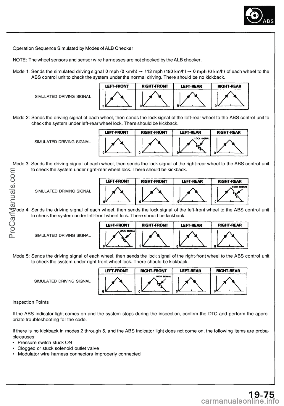
Operation Sequence Simulated by Modes of ALB Checker
NOTE: The wheel sensors and sensor wire harnesses are not checked by the ALB checker.
Mode 1: Sends the simulated driving signal of each wheel to the
ABS control unit to check the system under the normal driving. There should be no kickback.
Mode 2: Sends the driving signal of each wheel, then sends the lock signal of the left-rear wheel to the ABS control unit to
check the system under left-rear wheel lock. There should be kickback.
Mode 3: Sends the driving signal of each wheel, then sends the lock signal of the right-rear wheel to the ABS control unit
to check the system under right-rear wheel lock. There should be kickback.
Mode 4: Sends the driving signal of each wheel, then sends the lock signal of the left-front wheel to the ABS control unit
to check the system under left-front wheel lock. There should be kickback.
Mode 5: Sends the driving signal of each wheel, then sends the lock signal of the right-front wheel to the ABS control unit
to check the system under right-front wheel lock. There should be kickback.
Inspection Points
If the ABS indicator light comes on and the system stops during the inspection, confirm the DTC and perform the appro-
priate troubleshooting for the code.
If there is no kickback in modes 2 through 5, and the ABS indicator light does not come on, the following items are proba-
ble causes:
• Pressure switch stuck ON
• Clogged or stuck solenoid outlet valve
• Modulator wire harness connectors improperly connected
SIMULATED DRIVING SIGNAL
SIMULATED DRIVING SIGNAL
SIMULATED DRIVING SIGNAL
SIMULATED DRIVING SIGNAL
SIMULATED DRIVING SIGNALProCarManuals.com
Page 1047 of 1503
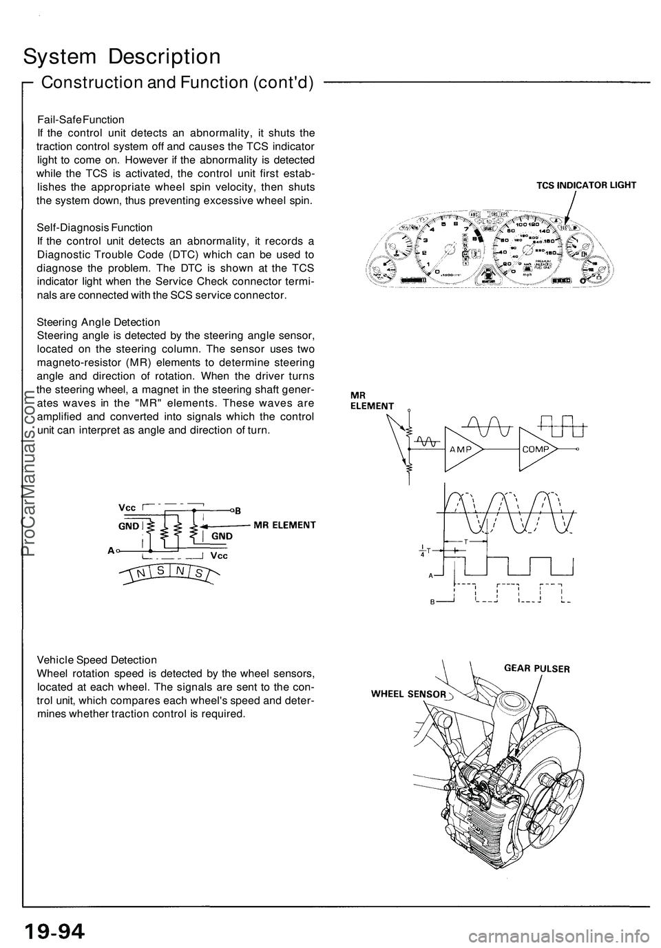
Construction and Function (cont'd)
System Description
Fail-Safe Function
If the control unit detects an abnormality, it shuts the
traction control system off and causes the TCS indicator
light to come on. However if the abnormality is detected
while the TCS is activated, the control unit first estab-
lishes the appropriate wheel spin velocity, then shuts
the system down, thus preventing excessive wheel spin.
Self-Diagnosis Function
If the control unit detects an abnormality, it records a
Diagnostic Trouble Code (DTC) which can be used to
diagnose the problem. The DTC is shown at the TCS
indicator light when the Service Check connector termi-
nals are connected with the SCS service connector.
Steering Angle Detection
Steering angle is detected by the steering angle sensor,
located on the steering column. The sensor uses two
magneto-resistor (MR) elements to determine steering
angle and direction of rotation. When the driver turns
the steering wheel, a magnet in the steering shaft gener-
ates waves in the "MR" elements. These waves are
amplified and converted into signals which the control
unit can interpret as angle and direction of turn.
Vehicle Speed Detection
Wheel rotation speed is detected by the wheel sensors,
located at each wheel. The signals are sent to the con-
trol unit, which compares each wheel's speed and deter-
mines whether traction control is required.ProCarManuals.com
Page 1051 of 1503
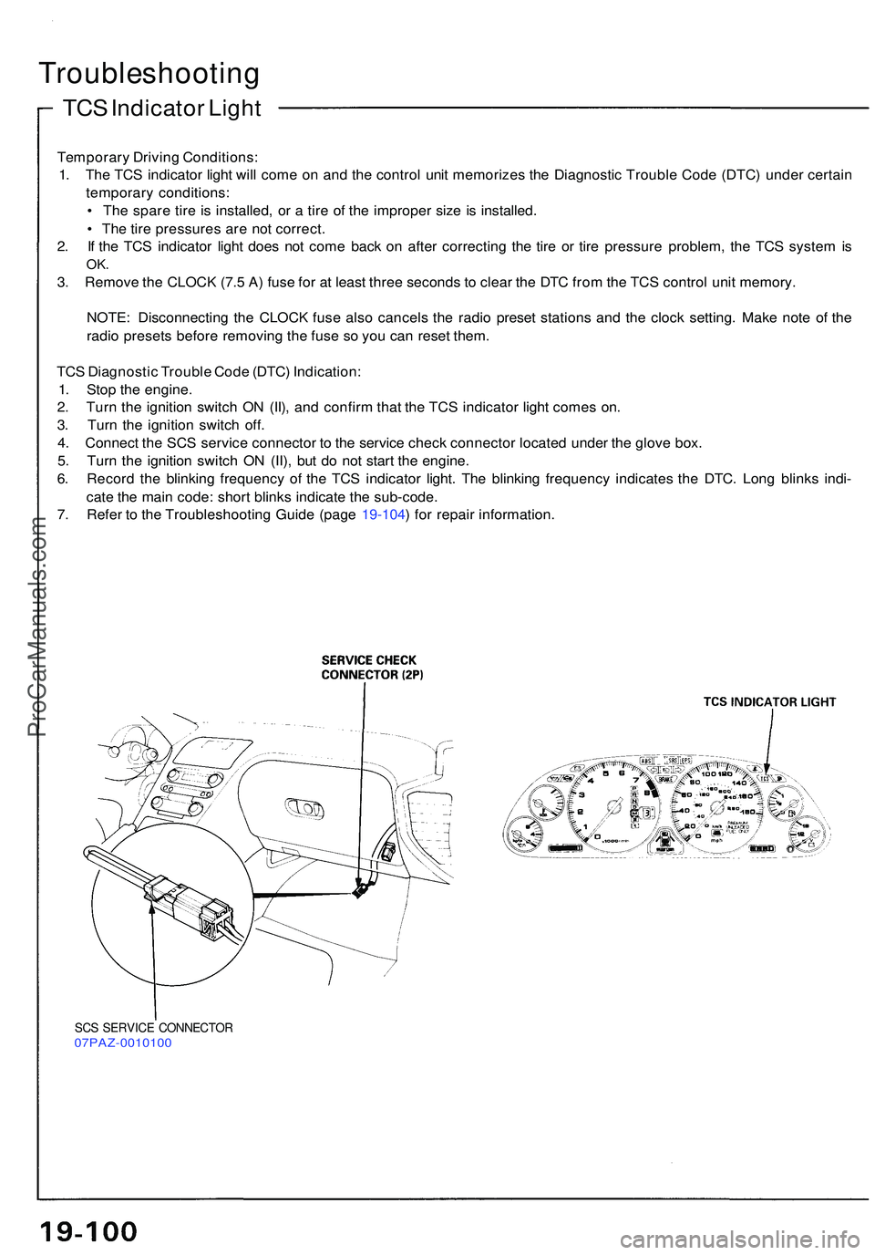
TCS Indicato r Ligh t
Troubleshootin g
Temporary Drivin g Conditions :
1 . Th e TC S indicato r ligh t wil l com e o n an d th e contro l uni t memorize s th e Diagnosti c Troubl e Cod e (DTC ) unde r certai n
temporar y conditions :
• Th e spar e tir e is installed , o r a tir e o f th e imprope r siz e is installed .
• Th e tir e pressure s ar e no t correct .
2 . I f th e TC S indicato r ligh t doe s no t com e bac k o n afte r correctin g th e tir e o r tir e pressur e problem , th e TC S syste m is
OK .
3. Remov e th e CLOC K (7. 5 A ) fus e fo r a t leas t thre e second s t o clea r th e DT C fro m th e TC S contro l uni t memory .
NOTE : Disconnectin g th e CLOC K fus e als o cancel s th e radi o prese t station s an d th e cloc k setting . Mak e not e o f th e
radi o preset s befor e removin g th e fus e s o yo u ca n rese t them .
TC S Diagnosti c Troubl e Cod e (DTC ) Indication :
1 . Sto p th e engine .
2 . Tur n th e ignitio n switc h O N (II) , an d confir m tha t th e TC S indicato r ligh t come s on .
3 . Tur n th e ignitio n switc h off .
4 . Connec t th e SC S servic e connecto r t o th e servic e chec k connecto r locate d unde r th e glov e box .
5 . Tur n th e ignitio n switc h O N (II) , bu t d o no t star t th e engine .
6 . Recor d th e blinkin g frequenc y o f th e TC S indicato r light . Th e blinkin g frequenc y indicate s th e DTC . Lon g blink s indi -
cat e th e mai n code : shor t blink s indicat e th e sub-code .
7 . Refe r t o th e Troubleshootin g Guid e (pag e 19-104 ) fo r repai r information .
SCS SERVIC E CONNECTO R07PAZ-001010 0
ProCarManuals.com
Page 1052 of 1503
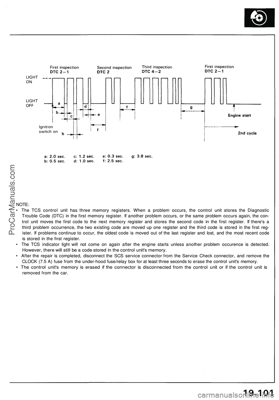
NOTE:
• The TCS control unit has three memory registers. When a problem occurs, the control unit stores the Diagnostic
Trouble Code (DTC) in the first memory register. If another problem occurs, or the same problem occurs again, the con-
trol unit moves the first code to the next memory register and stores the second code in the first register. If there's a
third problem occurrence, the two existing code are moved up one register and the third code is stored in the first reg-
ister. If problems continue to occur, the oldest code is moved out of the last register and lost, and the most recent code
is stored in the first register.
• The TCS indicator light will not come on again after the engine starts unless another problem occurence is detected.
However, there will still be a code stored in the control unit's memory.
• After the repair is completed, disconnect the SCS service connector from the Service Check connector, and remove the
CLOCK (7.5 A) fuse from the under-hood fuse/relay box for at least three seconds to erase the control unit's memory.
• The control unit's memory is erased if the connector is disconnected from the control unit or if the control unit is
removed from the car.ProCarManuals.com