1997 ACURA NSX light
[x] Cancel search: lightPage 1308 of 1503
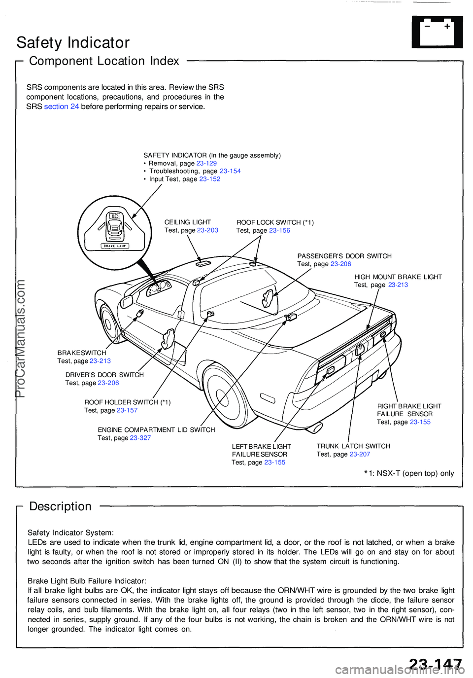
Safety Indicato r
Componen t Locatio n Inde x
SRS component s ar e locate d in thi s area . Revie w th e SR S
componen t locations , precautions , an d procedure s i n th e
SR S sectio n 24 befor e performin g repair s o r service .
SAFET Y INDICATO R (I n th e gaug e assembly )
• Removal , pag e 23-12 9
• Troubleshooting , pag e 23-15 4
• Inpu t Test , pag e 23-15 2
ROOF LOC K SWITC H (*1 )
Test , pag e 23-15 6
PASSENGER' S DOO R SWITC H
Test , pag e 23-20 6
HIG H MOUN T BRAK E LIGH T
Test , pag e 23-21 3
CEILIN
G LIGH T
Test , pag e 23-20 3
BRAK E SWITC H
Test , pag e 23-21 3
DRIVER' S DOO R SWITC H
Test , pag e 23-20 6
ROO F HOLDE R SWITC H (*1 )
Test , pag e 23-15 7
ENGIN E COMPARTMEN T LI D SWITC H
Test , pag e 23-32 7 RIGH
T BRAK E LIGH T
FAILUR E SENSO R
Test , pag e 23-15 5
LEF T BRAK E LIGH T
FAILUR E SENSO R
Test , pag e 23-15 5 TRUN
K LATC H SWITC H
Test , pag e 23-20 7
1: NSX- T (ope n top ) onl y
Descriptio n
Safety Indicato r System :
LEDs ar e use d t o indicat e whe n th e trun k lid , engin e compartmen t lid , a door , o r th e roo f i s no t latched , o r whe n a brak e
light i s faulty , o r whe n th e roo f i s no t store d o r improperl y store d i n it s holder . Th e LED s wil l g o o n an d sta y o n fo r abou t
tw o second s afte r th e ignitio n switc h ha s bee n turne d O N (II ) t o sho w tha t th e syste m circui t i s functioning .
Brak e Ligh t Bul b Failur e Indicator :
If al l brak e ligh t bulb s ar e OK , th e indicato r ligh t stay s of f becaus e th e ORN/WH T wir e is grounde d b y th e tw o brak e ligh t
failur e sensor s connecte d i n series . Wit h th e brak e light s off , th e groun d i s provide d throug h th e diode , th e failur e senso r
rela y coils , an d bul b filaments . Wit h th e brak e ligh t on , al l fou r relay s (tw o i n th e lef t sensor , tw o i n th e righ t sensor) , con -
necte d i n series , suppl y ground . I f an y o f th e fou r bulb s i s no t working , th e chai n i s broke n an d th e ORN/WH T wir e i s no t
longe r grounded . Th e indicato r ligh t come s on .
ProCarManuals.com
Page 1312 of 1503
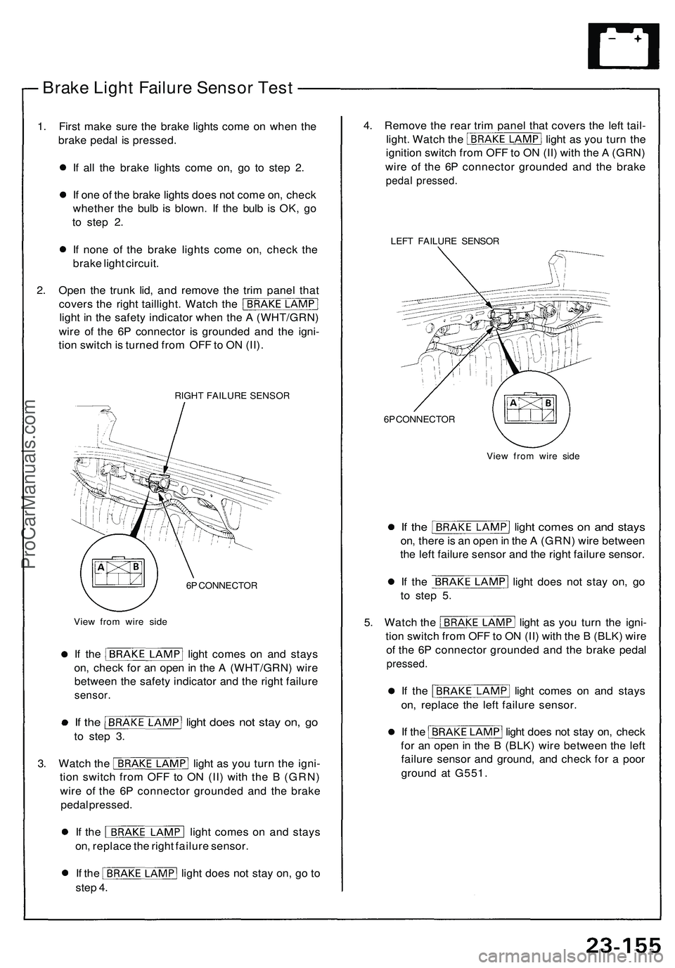
Brake Ligh t Failur e Senso r Tes t
1. Firs t mak e sur e th e brak e light s com e o n whe n th e
brak e peda l i s pressed .
I f al l th e brak e light s com e on , g o t o ste p 2 .
I f on e o f th e brak e light s doe s no t com e on , chec k
whethe r th e bul b i s blown . I f th e bul b i s OK , g o
t o ste p 2 .
I f non e o f th e brak e light s com e on , chec k th e
brak e ligh t circui t.
2 . Ope n th e trun k lid , an d remov e th e tri m pane l tha t
cover s th e righ t taillight . Watc h th e
ligh t i n th e safet y indicato r whe n th e A (WHT/GRN )
wir e o f th e 6 P connecto r i s grounde d an d th e igni -
tio n switc h is turne d fro m OF F to O N (II) .
RIGH T FAILUR E SENSO R
6 P CONNECTO R
Vie w fro m wir e sid e LEF
T FAILUR E SENSO R
6 P CONNECTO R
View fro m wir e sid e
If th e ligh t come s o n an d stay s
on, ther e is a n ope n in th e A (GRN ) wir e betwee n
th e lef t failur e senso r an d th e righ t failur e sensor .
If th e ligh t doe s no t sta y on , g o
t o ste p 5 .
5. Watc h th e ligh t a s yo u tur n th e igni -
tio n switc h fro m OF F to O N (II ) wit h th e B (BLK ) wir e
o f th e 6 P connecto r grounde d an d th e brak e peda l
pressed .
If th e ligh t come s o n an d stay s
on , replac e th e lef t failur e sensor .
If th e ligh t doe s no t sta y on , chec k
fo r a n ope n in th e B (BLK ) wir e betwee n th e lef t
failur e senso r an d ground , an d chec k fo r a poo r
groun d a t G551 .
If th e ligh t come s o n an d stay s
on , chec k fo r a n ope n in th e A (WHT/GRN ) wir e
betwee n th e safet y indicato r an d th e righ t failur e
sensor .
If th e ligh t doe s no t sta y on , g o
to ste p 3 .
3. Watc h th e ligh t a s yo u tur n th e igni -
tio n switc h fro m OF F t o O N (II ) wit h th e B (GRN )
wir e o f th e 6 P connecto r grounde d an d th e brak e
peda l pressed .
If th e ligh t come s o n an d stay s
on , replac e th e righ t failur e sensor .
If th e ligh t doe s no t sta y on , g o t o
ste p 4 . 4
. Remov e th e rea r tri m pane l tha t cover s th e lef t tail -
light . Watc h th e ligh t a s yo u tur n th e
ignitio n switc h fro m OF F to O N (II ) wit h th e A (GRN )
wir e o f th e 6 P connecto r grounde d an d th e brak e
pedal pressed .
ProCarManuals.com
Page 1317 of 1503
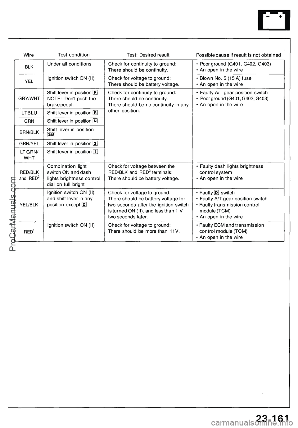
WireTes t conditio n
Test: Desire d resul t
Possible caus e if resul t i s no t obtaine d
BLK
YE L
GRY/WH T
LTBLU
GRN
BRN/BL K
GRN/YE L
LT GRN /
WHT
RED/BL K
and RED2
YEL/BL K
RED1
Under al l condition s
Ignitio n switc h O N (II )
Shif t leve r i n positio n
NOTE : Don' t pus h th e
brak e pedal .
Shift leve r i n positio n
Shift leve r i n positio n
Shif t leve r i n positio n
Shift leve r i n positio n
Shift leve r i n positio n
Combinatio n ligh t
switc h O N an d das h
light s brightnes s contro l
dia l o n ful l brigh t
Ignitio n switc h O N (II )
an d shif t leve r i n an y
positio n excep t
Ignitio n switc h O N (II ) Chec
k fo r continuit y t o ground :
Ther e shoul d b e continuity .
Chec k fo r voltag e to ground :
Ther e shoul d b e batter y voltage .
Chec k fo r continuit y t o ground :
Ther e shoul d b e continuity .
Ther e shoul d b e n o continuit y i n an y
othe r position .
Chec k fo r voltag e betwee n th e
RED/BL K an d RED2 terminals :
There shoul d b e batter y voltage .
Chec k fo r voltag e to ground :
Ther e shoul d b e batter y voltag e fo r
tw o second s afte r th e ignitio n switc h
i s turne d O N (II) , an d les s tha n 1 V
tw o second s later .
Chec k fo r voltag e t o ground :
Ther e shoul d b e mor e tha n 11V .
• Poo r groun d (G401 , G402 , G403 )
• A n ope n i n th e wir e
• Blow n No . 5 (1 5 A ) fus e
• A n ope n i n th e wir e
• Fault y A/ T gea r positio n switc h
• Poo r groun d (G401 , G402 , G403 )
• A n ope n i n th e wir e
• Fault y das h light s brightnes s
contro l syste m
• A n ope n i n th e wir e
• Fault y switc h
• Fault y A/ T gea r positio n switc h
• Fault y transmissio n contro l
modul e (TCM )
• A n ope n i n th e wir e
• Fault y EC M an d transmissio n
control modul e (TCM )
• A n ope n i n th e wir e
ProCarManuals.com
Page 1321 of 1503
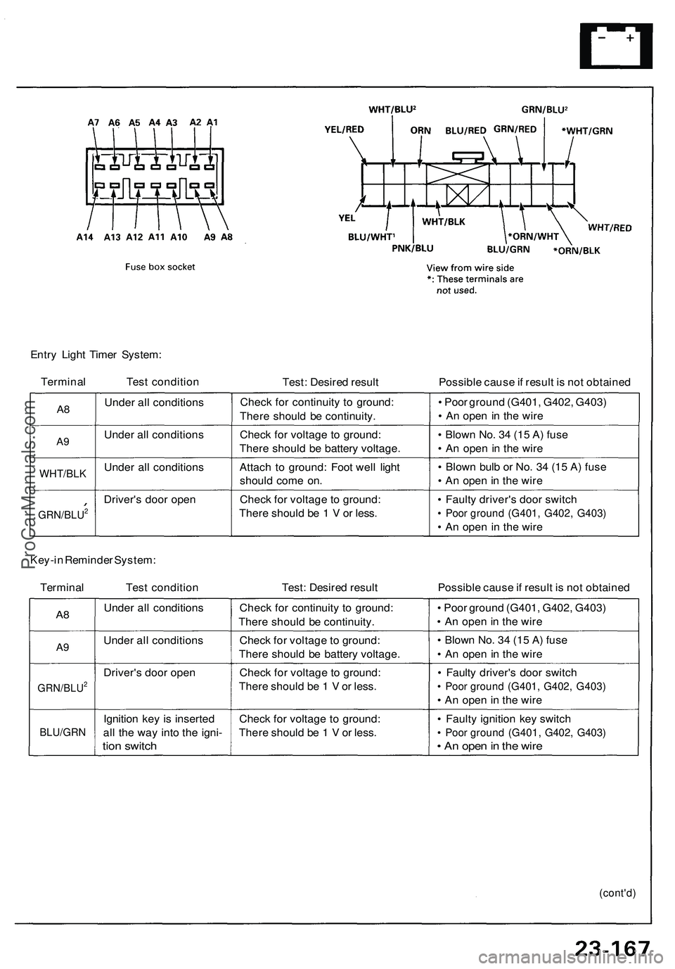
Entry Light Timer System:
Terminal Test condition
Test: Desired result
Possible cause if result is not obtained
A8
A9
WHT/BLK
GRN/BLU2
Under all conditions
Under all conditions
Under all conditions
Driver's door open
Check for continuity to ground:
There should be continuity.
Check for voltage to ground:
There should be battery voltage.
Attach to ground: Foot well light
should come on.
Check for voltage to ground:
There should be 1 V or less.
• Poor ground (G401, G402, G403)
• An open in the wire
• Blown No. 34 (15 A) fuse
• An open in the wire
• Blown bulb or No. 34 (15 A) fuse
• An open in the wire
• Faulty driver's door switch
• Poor ground (G401, G402, G403)
• An open in the wire
Key-in Reminder System:
Terminal Test condition
Test: Desired result
Possible cause if result is not obtained
A8
A9
GRN/BLU2
BLU/GRN
Under all conditions
Under all conditions
Driver's door open
Ignition key is inserted
all the way into the igni-
tion switch
Check for continuity to ground:
There should be continuity.
Check for voltage to ground:
There should be battery voltage.
Check for voltage to ground:
There should be 1 V or less.
Check for voltage to ground:
There should be 1 V or less.
• Poor ground (G401, G402, G403)
• An open in the wire
• Blown No. 34 (15 A) fuse
• An open in the wire
• Faulty driver's door switch
• Poor ground (G401, G402, G403)
• An open in the wire
• Faulty ignition key switch
• Poor ground (G401, G402, G403)
• An open in the wire
(cont'd)ProCarManuals.com
Page 1322 of 1503
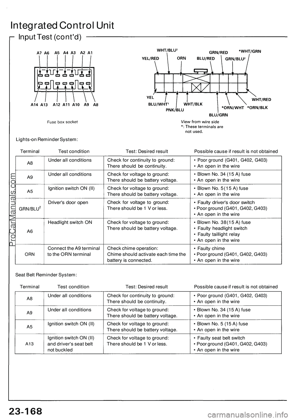
Integrated Control Unit
Input Test (cont'd)
Lights-on Reminder System:
Terminal
Test condition
Test: Desired result
Possible cause if result is not obtained
A8
A9
A5
GRN/BLU2
A6
ORN
Under all conditions
Under all conditions
Ignition switch ON (II)
Driver's door open
Headlight switch ON
Connect the A9 terminal
to the ORN terminal
Check for continuity to ground:
There should be continuity.
Check for voltage to ground:
There should be battery voltage.
Check for voltage to ground:
There should be battery voltage.
Check for voltage to ground:
There should be 1 V or less.
Check for voltage to ground:
There should be battery voltage.
Check chime operation:
Chime should activate each time the
battery is connected.
• Poor ground (G401, G402, G403)
• An open in the wire
• Blown No. 34 (15 A) fuse
• An open in the wire
• Blown No. 5(15 A) fuse
• An open in the wire
• Faulty driver's door switch
• Poor ground (G401, G402, G403)
• An open in the wire
• Blown No. 38(15 A) fuse
• Faulty headlight switch
• Faulty taillight relay
• An open in the wire
• Faulty chime
• Poor ground (G401, G402, G403)
• An open in the wire
Seat Belt Reminder System:
Terminal Test condition
Test: Desired result
Possible cause if result is not obtained
A8
A9
A5
A13
Under all conditions
Under all conditions
Ignition switch ON (II)
Ignition switch ON (II)
and driver's seat belt
not buckled
Check for continuity to ground:
There should be continuity.
Check for voltage to ground:
There should be battery voltage.
Check for voltage to ground:
There should be battery voltage.
Check for voltage to ground:
There should be 1 V or less.
• Poor ground (G401, G402, G403)
• An open in the wire
• Blown No. 34 (15 A) fuse
• An open in the wire
• Blown No. 5 (15 A) fuse
• An open in the wire
• Faulty seat belt switch
• Poor ground (G401, G402, G403)
• An open in the wireProCarManuals.com
Page 1323 of 1503
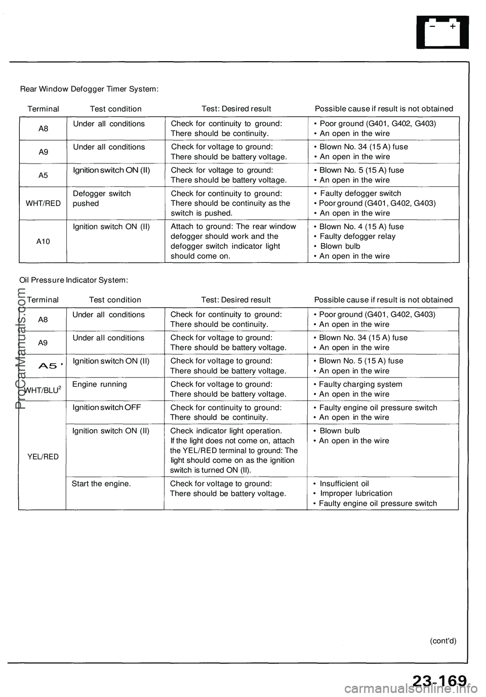
Rear Window Defogger Timer System:
Terminal Test condition
Test: Desired result
Possible cause if result is not obtained
A8
A9
A5
WHT/RED
A10
Under all conditions
Under all conditions
Ignition switch ON (II)
Defogger switch
pushed
Ignition switch ON (II)
Check for continuity to ground:
There should be continuity.
Check for voltage to ground:
There should be battery voltage.
Check for voltage to ground:
There should be battery voltage.
Check for continuity to ground:
There should be continuity as the
switch is pushed.
Attach to ground: The rear window
defogger should work and the
defogger switch indicator light
should come on.
• Poor ground (G401, G402, G403)
• An open in the wire
• Blown No. 34 (15 A) fuse
• An open in the wire
• Blown No. 5 (15 A) fuse
• An open in the wire
• Faulty defogger switch
• Poor ground (G401, G402, G403)
• An open in the wire
• Blown No. 4 (15 A) fuse
• Faulty defogger relay
• Blown bulb
• An open in the wire
Oil Pressure Indicator System:
Terminal Test condition
Test: Desired result
Possible cause if result is not obtained
A8
A9
A5 '
WHT/BLU2
YEL/RED
Under all conditions
Under all conditions
Ignition switch ON (II)
Engine running
Ignition switch OFF
Ignition switch ON (II)
Start the engine.
Check for continuity to ground:
There should be continuity.
Check for voltage to ground:
There should be battery voltage.
Check for voltage to ground:
There should be battery voltage.
Check for voltage to ground:
There should be battery voltage.
Check for continuity to ground:
There should be continuity.
Check indicator light operation.
If the light does not come on, attach
the YEL/RED terminal to ground: The
light should come on as the ignition
switch is turned ON (II).
Check for voltage to ground:
There should be battery voltage.
• Poor ground (G401, G402, G403)
• An open in the wire
• Blown No. 34 (15 A) fuse
• An open in the wire
• Blown No. 5 (15 A) fuse
• An open in the wire
• Faulty charging system
• An open in the wire
• Faulty engine oil pressure switch
• An open in the wire
• Blown bulb
• An open in the wire
• Insufficient oil
• Improper lubrication
• Faulty engine oil pressure switch
(cont'd)ProCarManuals.com
Page 1324 of 1503
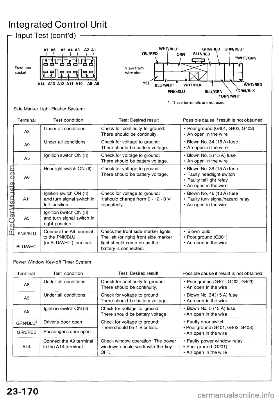
Integrated Contro l Uni t
Inpu t Tes t (cont'd )
Side Marke r Ligh t Flashe r System :
Termina l Tes
t conditio n Test: Desire d resul t Possible caus e if resul t i s no t obtaine d
A8
A9
A 5
A 6
A1 1
A3
PNK/BL U
BLU/WH T
Under al l condition s
Under al l condition s
Ignition switc h O N (II )
Headligh t switc h O N (II )
Ignitio n switc h O N (II )
and tur n signa l switc h in
lef t positio n
Ignition switc h O N (II )
an d tur n signa l switc h i n
righ t positio n
Connec t th e A 9 termina l
t o th e PNK/BL U
(o r BLU/WHT
1) terminal .Chec
k fo r continuit y t o ground :
Ther e shoul d b e continuity .
Chec k fo r voltag e t o ground :
Ther e shoul d b e batter y voltage .
Chec k fo r voltag e to ground :
Ther e shoul d b e batter y voltage .
Chec k fo r voltag e t o ground :
Ther e shoul d b e batter y voltage .
Chec k fo r voltag e t o ground :
It shoul d chang e fro m 0 - 1 2 - 0 V
repeatedly .
Chec k th e fron t sid e marke r lights :
Th e lef t (o r right ) fron t sid e marke r
ligh t shoul d com e o n a s th e
batter y is connected . •
Poo r groun d (G401 , G402 , G403 )
• A n ope n in th e wir e
• Blow n No . 3 4 (1 5 A ) fus e
• A n ope n in th e wir e
• Blow n No . 5 (1 5 A ) fus e
• A n ope n in th e wir e
• Blow n No . 3 8 (1 5 A ) fus e
• Fault y headligh t switc h
• Fault y tailligh t rela y
• A n ope n in th e wir e
• Blow n No . 4 6 (1 0 A ) fus e
• Fault y tur n signal/hazar d rela y
• A n ope n i n th e wir e
• Blow n bul b
• Poo r groun d (G301 )
• A n ope n in th e wir e
Powe r Windo w Key-of f Time r System :
Termina l Tes
t conditio n Test
: Desire d resul t
Possible caus e if resul t i s no t obtaine d
A8
A 9
A 5
GRN/BLU2
GRN/RE D
A14
Unde r al l condition s
Unde r al l condition s
Ignition switc h O N (II )
Driver' s doo r ope n
Passenger' s doo r ope n
Connec t th e A 9 termina l
to th e A1 4 terminal .
Check fo r continuit y t o ground :
Ther e shoul d b e continuity .
Chec k fo r voltag e t o ground :
Ther e shoul d b e batter y voltage .
Chec k fo r voltag e t o ground :
Ther e shoul d b e batter y voltage .
Chec k fo r voltag e t o ground :
Ther e shoul d b e 1 V or less .
Chec k windo w operation : Th e powe r
window s shoul d wor k wit h th e ke y
OFF .
• Poo r groun d (G401 , G402 , G403 )
• A n ope n i n th e wir e
• Blow n No . 34(1 5 A ) fus e
• A n ope n i n th e wir e
• Blow n No . 5 (1 5 A ) fus e
• A n ope n in th e wir e
• Fault y doo r switc h
• Poo r groun d (G401 , G402 , G403 )
• A n ope n in th e wir e
• Fault y powe r windo w rela y
• Poo r groun d (G201 )
• A n ope n in th e wir e
ProCarManuals.com
Page 1326 of 1503
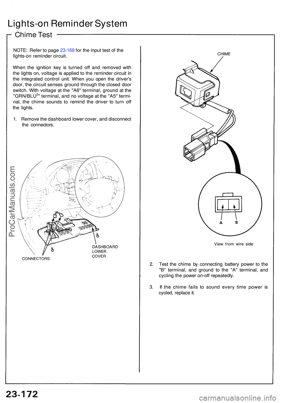
Lights-on Reminde r Syste m
Chime Tes t
NOTE : Refe r t o pag e 23-168 for the input test of the
lights-on reminde r circuit.
Whe n th e ignitio n ke y i s turne d of f an d remove d wit h
th e light s on , voltag e is applie d t o th e reminde r circui t i n
th e integrate d contro l unit . Whe n yo u ope n th e driver' s
door , th e circui t sense s groun d throug h th e close d doo r
switch . Wit h voltag e a t th e "A6 " terminal , groun d a t th e
"GRN/BLU
2" terminal , an d n o voltag e a t th e "A5 " termi -
nal , th e chim e sound s t o remin d th e drive r t o tur n of f
th e lights .
1 . Remov e th e dashboar d lowe r cover , an d disconnec t
th e connectors .
CONNECTOR S
DASHBOARDLOWERCOVER
CHIME
Vie w fro m wir e sid e
2. Tes t th e chim e b y connectin g batter y powe r t o th e
"B " terminal , an d groun d t o th e "A " terminal , an d
cyclin g th e powe r on-of f repeatedly .
3 . I f th e chim e fail s t o soun d ever y tim e powe r i s
cycled , replac e it .
ProCarManuals.com