Page 1093 of 1503

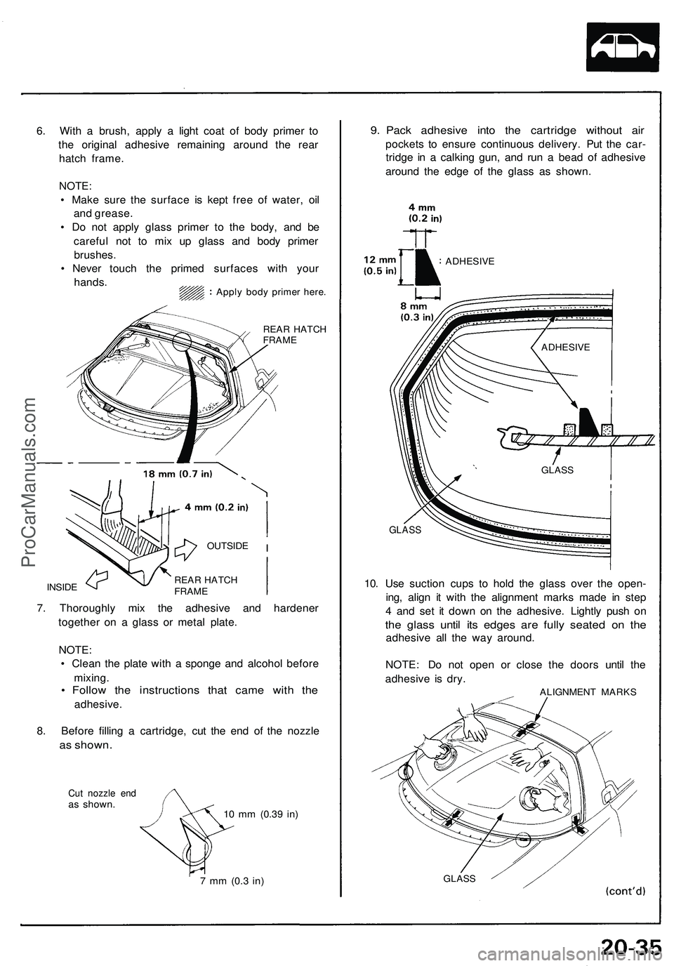
REAR HATCH
FRAME
INSIDE
7. Thoroughly mix the adhesive and hardener
together on a glass or metal plate.
NOTE:
• Clean the plate with a sponge and alcohol before
mixing.
• Follow the instructions that came with the
adhesive.
8. Before filling a cartridge, cut the end of the nozzle
as shown.
Cut nozzle end
as shown.
10 mm
(0.39
in)
7 mm
(0.3
in)
9. Pack adhesive into the cartridge without air
pockets to ensure continuous delivery. Put the car-
tridge in a calking gun, and run a bead of adhesive
around the edge of the glass as shown.
GLASS
10. Use suction cups to hold the glass over the open-
ing, align it with the alignment marks made in step
4 and set it down on the adhesive. Lightly push on
the glass until its edges are fully seated on the
adhesive all the way around.
NOTE: Do not open or close the doors until the
adhesive is dry.
ALIGNMENT MARKS
GLASS
6. With a brush, apply a light coat of body primer to
the original adhesive remaining around the rear
hatch frame.
NOTE:
• Make sure the surface is kept free of water, oil
and grease.
• Do not apply glass primer to the body, and be
careful not to mix up glass and body primer
brushes.
• Never touch the primed surfaces with your
hands.
Apply body primer here.
ADHESIVE
ADHESIVE
GLASS
REAR HATCH
FRAME
OUTSIDEProCarManuals.com
Page 1117 of 1503
Front Bumper
Replacement
1. Loosen the mounting screw, then pull the right and left front turn signal lights out and disconnect the connectors.
2. Remove the skirt covers, then remove the bumper mounting bolts on each side, and lower skirt mounting bolt.
3. Lower the inner fender, then remove the bumper mounting nuts and the skirt mounting bolts from inside the front
fender on each side.
4. Lift and remove the front bumper.
NOTE:
• Disconnect the washer hose, horn connecters, and ambient sensor connector.
• An assistant is helpful when removing the front bumper.
• Take care not to scratch the front bumper.
5. Installation is the reverse of the removal procedure.
NOTE: Insert the bumper bracket hooks into the bumper bracket holes.ProCarManuals.com
Page 1122 of 1503
Trunk Lid
Replacement/Adjustment
1. Remove the mounting screws, then remove the rear hatch air scoop.
2. Disconnect the high-mount brake light harness connector, and remove the harness clamp from the support strut.
3. Remove the trunk lid by removing the trunk lid mounting bolts.
4. Installation is the reverse of the removal procedure.
NOTE:
• Make sure the high-mount brake light connector is connected properly.
• Adjust the trunk lid alignment.ProCarManuals.com
Page 1153 of 1503
Roof
- Loc k Receiver s Adjustmen t
NOTE: Thi s adjustmen t shoul d b e don e i n th e followin g
orde r afte r removin g o r replacin g th e loc k receiver .
1 . Loose n th e loc k receive r mountin g bolt s a t eac h o f
th e fou r corners , the n tighte n the m lightly .
Front:
FRON T LOC KRECEIVE R
Rear:
2. Instal l th e roo f o n th e body .
REAR LOC KRECEIVE R
CAUTION : Whe n installin g th e roof , mak e sur e
bot h roo f sid e lock s ar e unlocked .
NOTE:
• Mak e sur e eac h roo f sid e hoo k align s wit h th e
hoo k sto p properly .
• Befor e securin g th e roo f b y turnin g eac h roo f
sid e loc k handle , chec k tha t th e roo f sid e retaine r
align s agains t th e fron t pilla r retaine r an d rea r
pilla r pane l evenl y a t eac h side , an d chec k tha t
th e seal s fi t flush .
ProCarManuals.com
Page 1169 of 1503

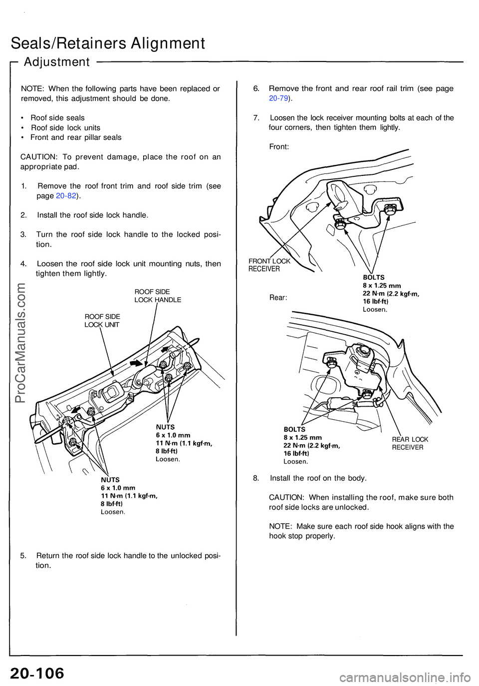
Seals/Retainers Alignmen t
Adjustmen t
NOTE: Whe n th e followin g part s hav e bee n replace d o r
removed , thi s adjustmen t shoul d b e done .
• Roo f sid e seal s
• Roo f sid e loc k unit s
• Fron t an d rea r pilla r seal s
CAUTION : T o preven t damage , plac e th e roo f o n a n
appropriat e pad .
1 . Remov e th e roo f fron t tri m an d roo f sid e tri m (se e
pag e 20-82 ).
2 . Instal l th e roo f sid e loc k handle .
3 . Tur n th e roo f sid e loc k handl e t o th e locke d posi -
tion.
4. Loose n th e roo f sid e loc k uni t mountin g nuts , the n
tighte n the m lightly .
ROOF SID E
LOC K HANDL E
ROO F SID E
LOC K UNI T
5. Retur n th e roo f sid e loc k handl e to th e unlocke d posi -
tion.
6. Remov e th e fron t an d rea r roo f rai l tri m (se e pag e
20-79 ).
7 . Loose n th e loc k receive r mountin g bolt s a t eac h o f th e
fou r corners , the n tighte n the m lightly .
Front :
FRON T LOC KRECEIVE R
Rear:
REAR LOC KRECEIVE R
8. Instal l th e roo f o n th e body .
CAUTION : Whe n installin g th e roof , mak e sur e bot h
roo f sid e lock s ar e unlocked .
NOTE : Mak e sur e eac h roo f sid e hoo k align s wit h th e
hoo k sto p properly .
ProCarManuals.com
Page 1186 of 1503

Troubleshooting
Self-diagnosis Circui t Chec k
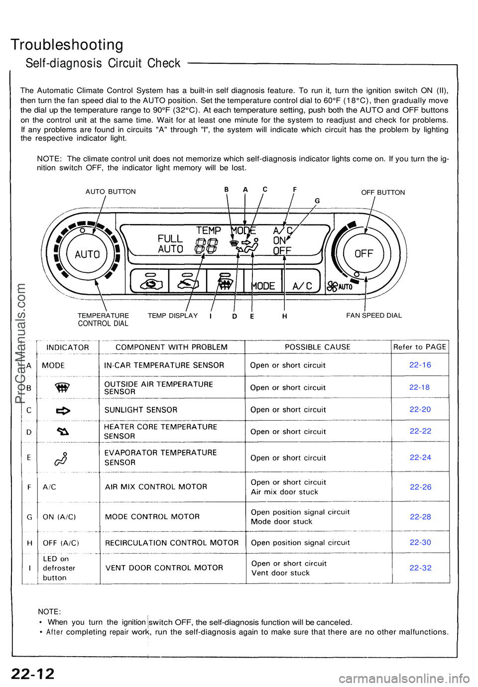
The Automati c Climat e Contro l Syste m ha s a built-i n sel f diagnosi s feature . T o ru n it , tur n th e ignitio n switc h O N (II) ,
the n tur n th e fa n spee d dia l t o th e AUT O position . Se t th e temperatur e contro l dia l t o 60° F (18°C) , the n graduall y mov e
the dia l u p th e temperatur e rang e to 90° F (32°C) . A t eac h temperatur e setting , pus h bot h th e AUT O an d OF F button s
on th e contro l uni t a t th e sam e time . Wai t fo r a t leas t on e minut e fo r th e syste m to readjus t an d chec k fo r problems .
I f an y problem s ar e foun d i n circuit s "A " throug h "I" , th e syste m wil l indicat e whic h circui t ha s th e proble m b y lightin g
th e respectiv e indicato r light .
NOTE : Th e climat e contro l uni t doe s no t memoriz e whic h self-diagnosi s indicato r light s com e on . I f yo u tur n th e ig -
nitio n switc h OFF , th e indicato r ligh t memor y wil l b e lost .
AUT O BUTTO NOFF BUTTO N
TEMPERATUR E TEM P DISPLA Y
CONTRO L DIA LFAN SPEE D DIA L
NOTE :
• Whe n yo u tur n th e ignitio nswitch OFF , th e self-diagnosi s functio n wil l b e canceled .
• After completin g repair work, run th e self-diagnosi s agai n to mak e sure that ther e are n o othe r malfunctions .
22-16
22-18
22-2 0
22-2 2
22-2 4
22-2 6
22-2 8
22-3 0
22-3 2
ProCarManuals.com
Page 1200 of 1503
Sunlight Sensor
Removal
Protect the dashboard with a shop towel, then with a
small screwdriver, carefully pry the sunlight sensor out
of the dashboard and disconnect its connector.
SUNLIGHT
SENSOR
Test
Measure the voltage between the terminals with the sen-
sor out of direct sunlight.
• With the connector connected (probe the back of it):
1.4 ± 0.2 V
• With the connector disconnected: 0.1 - 0.2 VProCarManuals.com
Page 1207 of 1503

A/C System Service
Performance Test
The performance test will help determine if the air con-
ditioning system is operating within specifications.
Only use service equipment that is U.L.-listed and is cer-
tified to meet the requirements of SAE J2210 to remove
HFC-134a (R-134a) from the air conditioning system.
CAUTION: Exposure to air conditioner refrigerant
and lubricant vapor or mist can irritate eyes, nose
and throat. Avoid breathing the air conditioner
refrigerant and lubricant vapor or mist.
If accidental system discharge occurs, ventilate work
area before resuming service.
R-134a service equipment or vehicle air conditioning sys-
tem should not be pressure tested or leak tested with
compressed air.
Some mixtures of air and R-134a have
been shown to be combustible at elevated pressures
and can result in fire or explosion causing injury or
property damage. Never use compressed air to pres-
sure test R-134a service equipment or vehicle air
conditioning systems.
Additional health and safety information may be obtained
from the refrigerant and lubricant manufacturers.
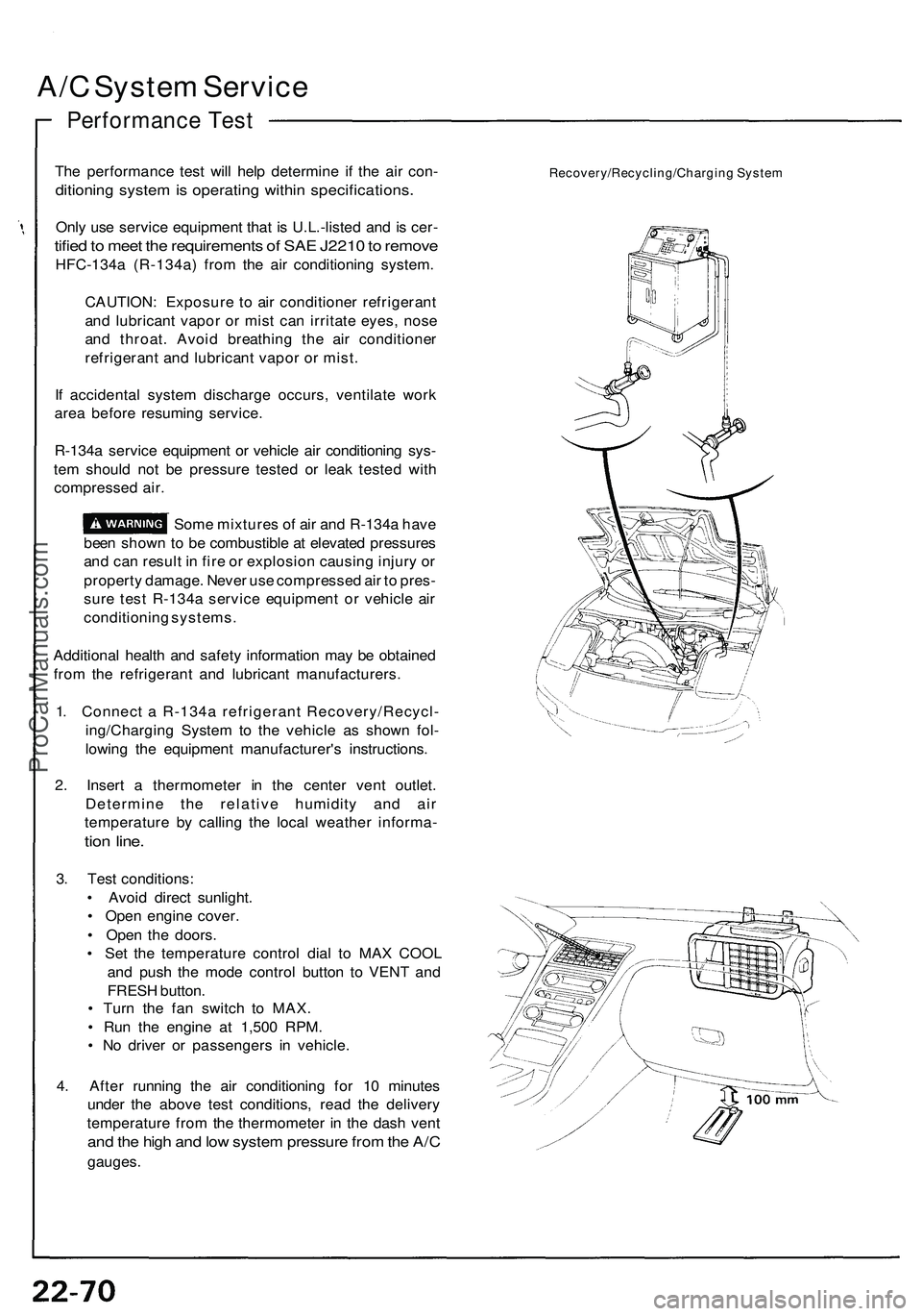
1. Connect a R-134a refrigerant Recovery/Recycl-
ing/Charging System to the vehicle as shown fol-
lowing the equipment manufacturer's instructions.
2. Insert a thermometer in the center vent outlet.
Determine the relative humidity and air
temperature by calling the local weather informa-
tion line.
3. Test conditions:
• Avoid direct sunlight.
• Open engine cover.
• Open the doors.
• Set the temperature control dial to MAX COOL
and push the mode control button to VENT and
FRESH button.
• Turn the fan switch to MAX.
• Run the engine at 1,500 RPM.
• No driver or passengers in vehicle.
4. After running the air conditioning for 10 minutes
under the above test conditions, read the delivery
temperature from the thermometer in the dash vent
and the high and low system pressure from the A/C
gauges.
Recovery/Recycling/Charging SystemProCarManuals.com