1997 ACURA NSX light
[x] Cancel search: lightPage 1468 of 1503
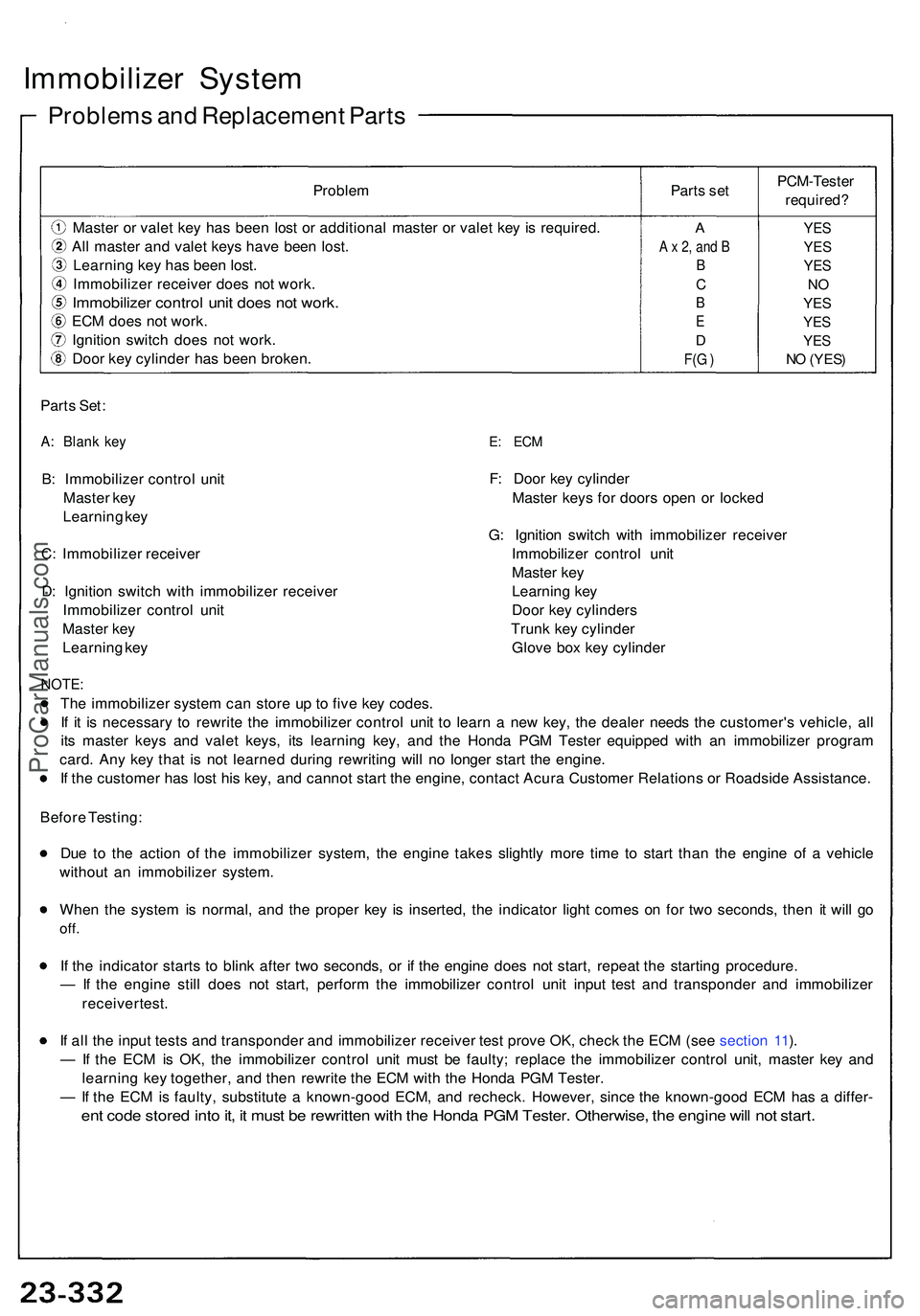
Immobilizer Syste m
Problem s an d Replacemen t Part s
Parts Set :
A: Blan k ke y
B: Immobilize r contro l uni t
Maste r ke y
Learnin g ke y
C : Immobilize r receive r
D : Ignitio n switc h wit h immobilize r receive r
Immobilize r contro l uni t
Maste r ke y
Learnin g ke y
E: EC M
F: Doo r ke y cylinde r
Maste r key s fo r door s ope n o r locke d
G : Ignitio n switc h wit h immobilize r receive r
Immobilize r contro l uni t
Maste r ke y
Learnin g ke y
Doo r ke y cylinder s
Trun k ke y cylinde r
Glov e bo x ke y cylinde r
NOTE:
The immobilize r syste m ca n stor e u p t o fiv e ke y codes .
I f i t i s necessar y t o rewrit e th e immobilize r contro l uni t t o lear n a ne w key , th e deale r need s th e customer' s vehicle , al l
it s maste r key s an d vale t keys , it s learnin g key , an d th e Hond a PG M Teste r equippe d wit h a n immobilize r progra m
card . An y ke y tha t i s no t learne d durin g rewritin g wil l n o longe r star t th e engine .
I f th e custome r ha s los t hi s key , an d canno t star t th e engine , contac t Acur a Custome r Relation s o r Roadsid e Assistance .
Befor e Testing :
Du e t o th e actio n o f th e immobilize r system , th e engin e take s slightl y mor e tim e t o star t tha n th e engin e o f a vehicl e
withou t a n immobilize r system .
Whe n th e syste m is normal , an d th e prope r ke y i s inserted , th e indicato r ligh t come s o n fo r tw o seconds , the n i t wil l g o
off .
If th e indicato r start s t o blin k afte r tw o seconds , o r i f th e engine does no t start , repea t th e startin g procedure .
— If th e engin e stil l doe s no t start , perfor m th e immobilize r contro l uni t inpu t tes t an d transponde r an d immobilize r
receive r test .
I f al l th e inpu t test s an d transponde r an d immobilize r receive r tes t prov e OK , chec k th e EC M (se e sectio n 11 ).
— If th e EC M is OK , th e immobilize r contro l uni t mus t b e faulty ; replac e th e immobilize r contro l unit , maste r ke y an d
learnin g ke y together , an d the n rewrit e th e EC M wit h th e Hond a PG M Tester .
— If th e EC M is faulty , substitut e a known-goo d ECM , an d recheck . However , sinc e th e known-goo d EC M ha s a differ -
ent cod e store d int o it , i t mus t b e rewritte n wit h th e Hond a PG M Tester . Otherwise , th e engin e wil l no t start .
Proble m Parts se t
Maste r o r vale t ke y ha s bee n los t o r additiona l maste r o r vale t ke y i s required .
Al l maste r an d vale t key s hav e bee n lost .
Learnin g ke y ha s bee n lost .
Immobilize r receive r doe s no t work .
Immobilize r contro l uni t doe s no t work .
ECM doe s no t work .
Ignitio n switc h doe s no t work .
Doo r ke y cylinde r ha s bee n broken . PCM-Teste
r
required?
A
A x 2, and B
B
C
B
E
D
F(G )
YES
YES
YES
NO
YES
YES
YES
NO (YES)
ProCarManuals.com
Page 1470 of 1503
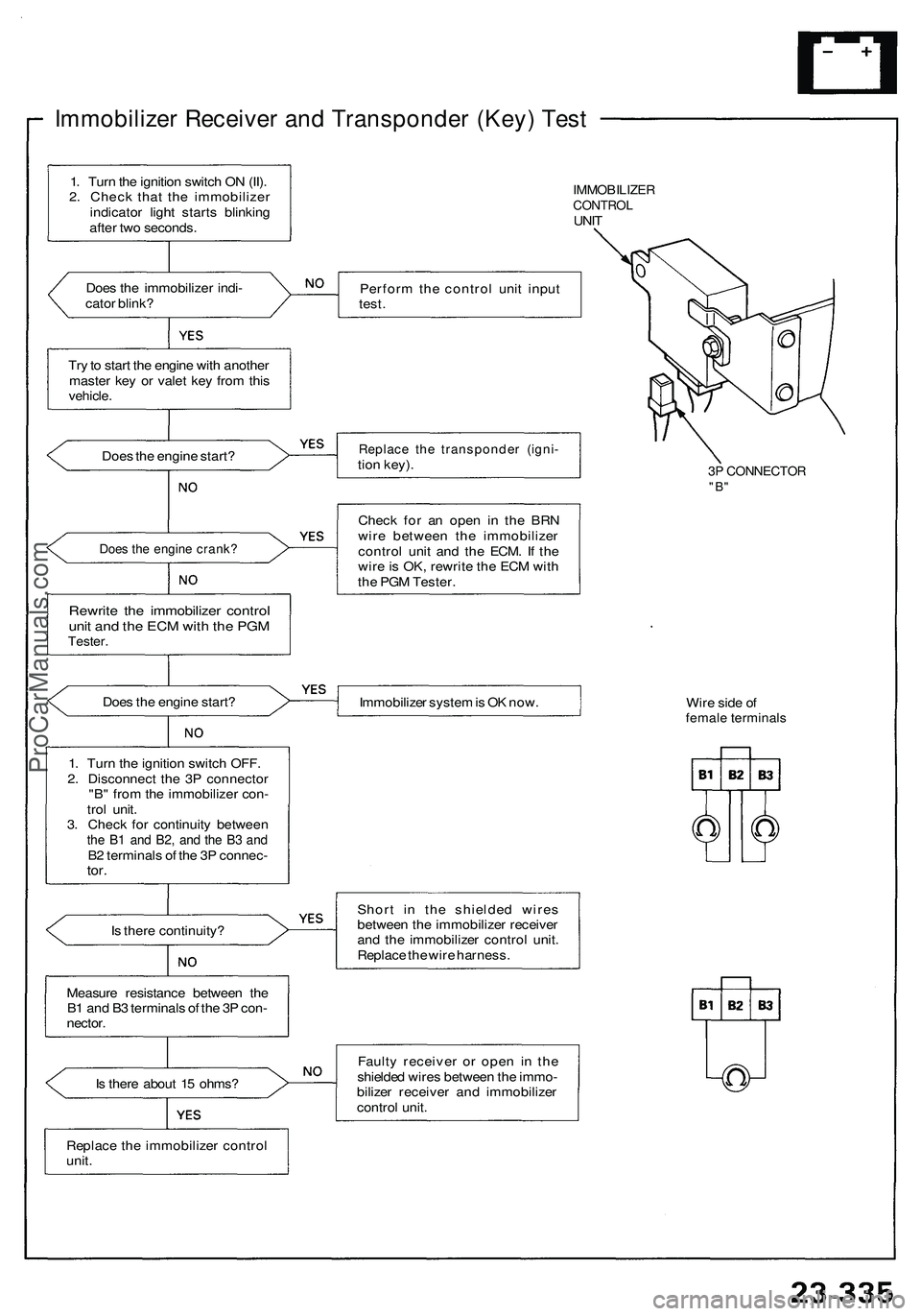
Immobilizer Receiver and Transponder (Key) Test
IMMOBILIZER
CONTROL
UNIT
Does the immobilizer indi-
cator blink?
Perform the control unit input
test.
Try to start the engine with another
master key or valet key from this
vehicle.
Does the engine start?
Replace the transponder (igni-
tion key).
3P CONNECTOR
"B"
Does the engine crank?
Rewrite the immobilizer control
unit and the ECM with the PGM
Tester.
Check for an open in the BRN
wire between the immobilizer
control unit and the ECM. If the
wire is OK, rewrite the ECM with
the PGM Tester.
Does the engine start?
Immobilizer system is OK now.
Wire side of
female terminals
Is there continuity?
Short in the shielded wires
between the immobilizer receiver
and the immobilizer control unit.
Replace the wire harness.
Measure resistance between the
B1 and B3 terminals of the 3P con-
nector.
Is there about 15 ohms?
Faulty receiver or open in the
shielded wires between the immo-
bilizer receiver and immobilizer
control unit.
Replace the immobilizer control
unit.
1. Turn the ignition switch ON (II).
2. Check that the immobilizer
indicator light starts blinking
after two seconds.
1. Turn the ignition switch OFF.
2. Disconnect the 3P connector
"B" from the immobilizer con-
trol unit.
3. Check for continuity between
the B1 and B2, and the B3 and
B2 terminals of the 3P connec-
tor.ProCarManuals.com
Page 1483 of 1503
Troubleshooting
Self-diagnosis Functio n
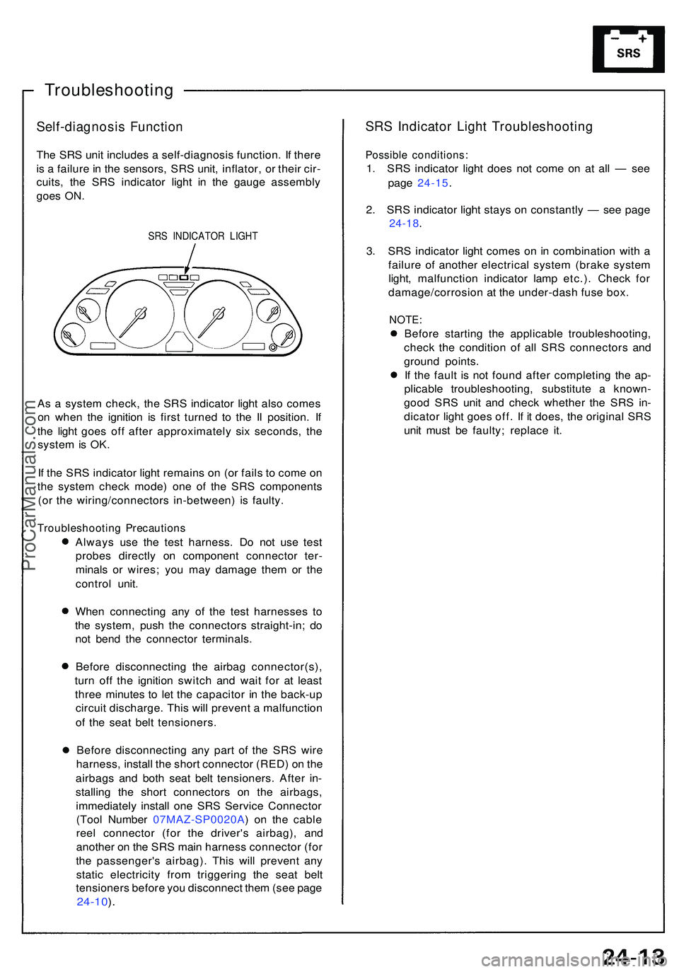
The SR S uni t include s a self-diagnosi s function . I f ther e
i s a failur e in th e sensors , SR S unit , inflator , o r thei r cir -
cuits , th e SR S indicato r ligh t i n th e gaug e assembl y
goe s ON .
SRS INDICATO R LIGH T
As a syste m check , th e SR S indicato r ligh t als o come s
o n whe n th e ignitio n i s firs t turne d t o th e I I position . I f
th e ligh t goe s of f afte r approximatel y si x seconds , th e
syste m is OK .
I f th e SR S indicato r ligh t remain s o n (o r fail s t o com e o n
th e syste m chec k mode ) on e o f th e SR S component s
(o r th e wiring/connector s in-between ) i s faulty .
Troubleshootin g Precaution s
Always us e th e tes t harness . D o no t us e tes t
probe s directl y o n componen t connecto r ter -
minal s o r wires ; yo u ma y damag e the m o r th e
contro l unit .
Whe n connectin g an y o f th e tes t harnesse s t o
th e system , pus h th e connector s straight-in ; d o
no t ben d th e connecto r terminals .
Befor e disconnectin g th e airba g connector(s) ,
tur n of f th e ignitio n switc h an d wai t fo r a t leas t
thre e minute s t o le t th e capacito r i n th e back-u p
circui t discharge . Thi s wil l preven t a malfunctio n
o f th e sea t bel t tensioners .
Befor e disconnectin g an y par t o f th e SR S wir e
harness , instal l th e shor t connecto r (RED ) o n th e
airbag s an d bot h sea t bel t tensioners . Afte r in -
stallin g th e shor t connector s o n th e airbags ,
immediatel y instal l on e SR S Servic e Connecto r
(Too l Numbe r 07MAZ-SP0020A ) o n th e cabl e
ree l connecto r (fo r th e driver' s airbag) , an d
anothe r o n th e SR S mai n harnes s connecto r (fo r
th e passenger' s airbag) . Thi s wil l preven t an y
stati c electricit y fro m triggerin g th e sea t bel t
tensioner s befor e yo u disconnec t the m (se e pag e
24-10 ).
SR S Indicato r Ligh t Troubleshootin g
Possible conditions :
1. SR S indicato r ligh t doe s no t com e o n a t al l — se e
pag e 24-15 .
2 . SR S indicato r ligh t stay s o n constantl y — se e pag e
24-18 .
3 . SR S indicato r ligh t come s o n in combinatio n wit h a
failur e o f anothe r electrica l syste m (brak e syste m
light , malfunctio n indicato r lam p etc.) . Chec k fo r
damage/corrosio n a t th e under-das h fus e box .
NOTE :
Before startin g th e applicabl e troubleshooting ,
chec k th e conditio n o f al l SR S connector s an d
groun d points .
I f th e faul t i s no t foun d afte r completin g th e ap -
plicabl e troubleshooting , substitut e a known -
goo d SR S uni t an d chec k whethe r th e SR S in -
dicato r ligh t goe s off . I f i t does , th e origina l SR S
uni t mus t b e faulty ; replac e it .
ProCarManuals.com
Page 1493 of 1503
Supplemental Restrain t Syste m (SRS )
Cable Ree l Remova l
Store a remove d airba g assembl y wit h th e
pa d surfac e up . I f the airba g i s improperl y store d fac e
down , accidenta l deploymen t coul d prope l th e uni t wit h
enoug h forc e t o caus e seriou s injury .
CAUTION :
Carefully inspec t th e airba g assembl y befor e install -
in g it . D o no t instal l a n airba g assembl y tha t show s
sign s o f bein g droppe d o r improperl y handled , suc h
as dents , crack s o r deformation .
Always kee p th e shor t connector s (RED ) o n th e air -
bag s whe n th e harnes s i s disconnected .
D o no t disassembl e o r tampe r wit h th e airba g
assembly .
1. Disconnec t th e batter y negativ e cabl e an d the n th e
positiv e cable .
2 . Befor e disconnectin g an y par t o f th e SR S wir e
harness , instal l th e shor t connector s (RED ) (se e pag e
24-10 ).
3 . Mak e sur e th e wheel s ar e aligne d straigh t ahead .
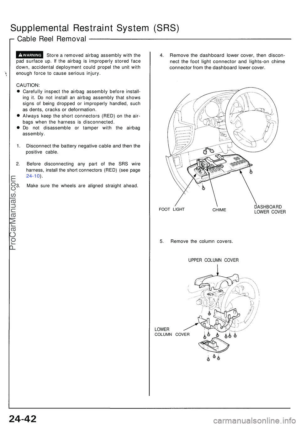
4. Remov e th e dashboar d lowe r cover , the n discon -
nect th e foo t ligh t connecto r an d lights-o n chim e
connecto r fro m th e dashboar d lowe r cover .
FOOT LIGH TCHIMEDASHBOAR DLOWER COVE R
5. Remov e th e colum n covers .
UPPER COLUM N COVE R
LOWE R
COLUM N COVE R
ProCarManuals.com
Page 1496 of 1503
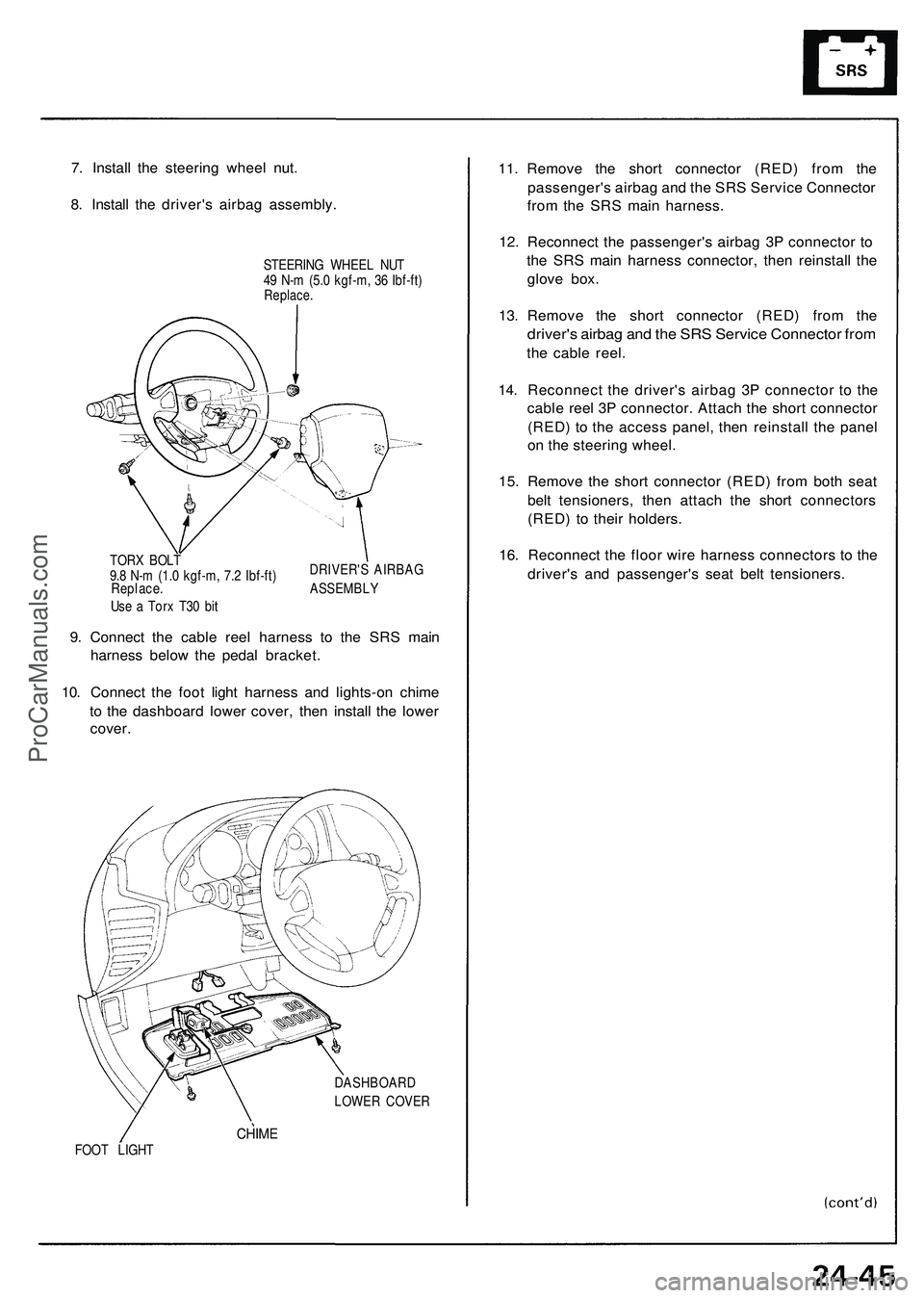
7. Instal l th e steerin g whee l nut .
8 . Instal l th e driver' s airba g assembly .
STEERING WHEE L NU T
4 9 N- m (5. 0 kgf-m , 3 6 Ibf-ft )
Replace .
DRIVER' S AIRBA G
TOR
X BOL T
9. 8 N- m (1. 0 kgf-m , 7. 2 Ibf-ft )
Replace . ASSEMBL Y
Us e a Tor x T3 0 bi t
9. Connec t th e cabl e ree l harnes s t o th e SR S mai n
harnes s belo w th e peda l bracket .
10 . Connec t th e foo t ligh t harnes s an d lights-o n chim e
t o th e dashboar d lowe r cover , the n instal l th e lowe r
cover .
DASHBOAR D
LOWE R COVE R
CHIMEFOOT LIGH T
11. Remov e th e shor t connecto r (RED ) fro m th e
passenger' s airba g an d th e SR S Servic e Connecto r
fro m th e SR S mai n harness .
1 2 . Reconnec t th e passenger' s airba g 3 P connecto r t o
th e SR S mai n harnes s connector , the n reinstal l th e
glov e box .
13 . Remov e th e shor t connecto r (RED ) fro m th e
driver' s airba g an d th e SR S Servic e Connecto r fro m
the cabl e reel .
14 . Reconnec t th e driver' s airba g 3 P connecto r t o th e
cabl e ree l 3 P connector . Attac h th e shor t connecto r
(RED ) t o th e acces s panel , the n reinstal l th e pane l
o n th e steerin g wheel .
15 . Remov e th e shor t connecto r (RED ) fro m bot h sea t
bel t tensioners , the n attac h th e shor t connector s
(RED ) t o thei r holders .
16 . Reconnec t th e floo r wir e harnes s connector s t o th e
driver' s an d passenger' s sea t bel t tensioners .
ProCarManuals.com
Page 1501 of 1503
Supplemental Restraint System (SRS)
SRS Unit Assembly Installation
CAUTION: Be sure to install the SRS wiring so that it is
not pinched or interfering with other car parts.
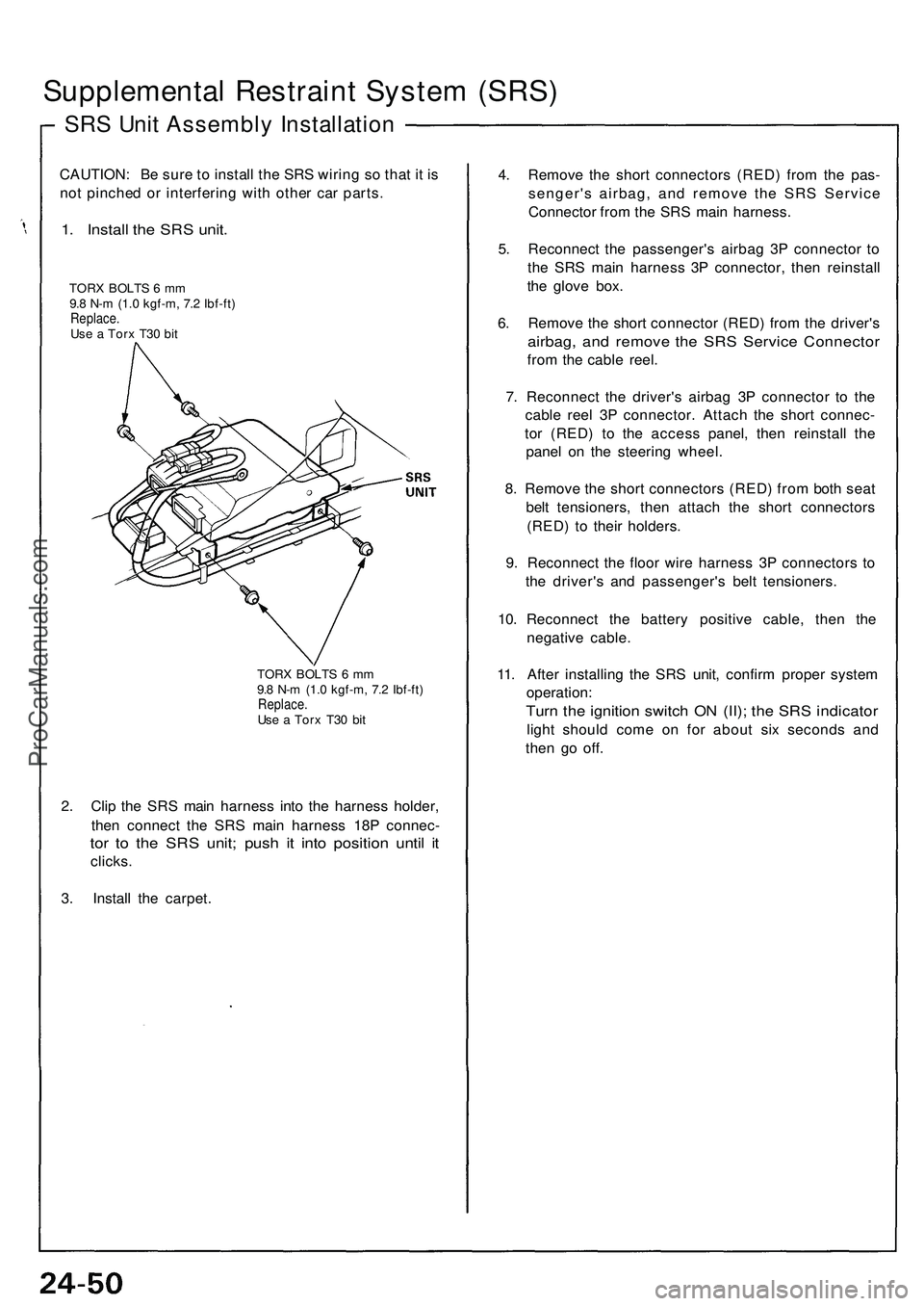
1. Install the SRS unit.
TORX BOLTS 6 mm
9.8 N-m (1.0 kgf-m, 7.2 Ibf-ft)
Replace.
Use a Torx T30 bit
TORX BOLTS 6 mm
9.8 N-m (1.0 kgf-m, 7.2 Ibf-ft)
Replace.
Use a Torx T30 bit
2. Clip the SRS main harness into the harness holder,
then connect the SRS main harness 18P connec-
tor to the SRS unit; push it into position until it
clicks.
3. Install the carpet.
4. Remove the short connectors (RED) from the pas-
senger's airbag, and remove the SRS Service
Connector from the SRS main harness.
5. Reconnect the passenger's airbag 3P connector to
the SRS main harness 3P connector, then reinstall
the glove box.
6. Remove the short connector (RED) from the driver's
airbag, and remove the SRS Service Connector
from the cable reel.
7. Reconnect the driver's airbag 3P connector to the
cable reel 3P connector. Attach the short connec-
tor (RED) to the access panel, then reinstall the
panel on the steering wheel.
8. Remove the short connectors (RED) from both seat
belt tensioners, then attach the short connectors
(RED) to their holders.
9. Reconnect the floor wire harness 3P connectors to
the driver's and passenger's belt tensioners.
10. Reconnect the battery positive cable, then the
negative cable.
11. After installing the SRS unit, confirm proper system
operation:
Turn the ignition switch ON (II); the SRS indicator
light should come on for about six seconds and
then go off.ProCarManuals.com