Page 1376 of 1503
1. Remove the dash lights brightness controller from
the instrument panel trim (see previous page).
2. Measure resistance between A and B terminals
while rotating the adjusting dial. Resistance should
vary from 0 to 20,000 ohms as the dial is rotated.
NOTE: Resistance will vary slightly with temperature.
HEADLIGHT
RETRACTOR SWITCH
ADJUSTING
DIAL
DASH LIGHTS
BRIGHTNESS
CONTROLLER
Controller Light Bulb Replacement
1. Remove the dash lights brightness controller.
2. Turn the socket 45° counterclockwise to remove it.
BULB (0.84 W)
Dash Lights Brightness Control
Controller TestProCarManuals.com
Page 1378 of 1503
Foot Well Light Replacement
1. Remove the dashboard lower cover.
2. Disconnect the 2P connector from the foot well light.
DASHBOARD LOWER COVER
2P CONNECTOR
FOOT WELL LIGHT
3. Push the foot well light out of the dashboard lower
cover.
4. Open the foot well light cover, then remove the bulb
from the housing.
HOUSING
COVER
BULB
(5W)ProCarManuals.com
Page 1379 of 1503
Removal
CAUTION: Be careful not to damage the center air vent
or clock.
1. Pull the clock out with your fingers (if necessary, use
a screwdriver).
2. Disconnect the 4P connector from the clock.
4P CONNECTOR
CENTER AIR VENT
Terminals
Terminal Wire Connects to
A
B
C
D
BLK
RED/BLK
WHT/YEL
YEL
Ground
Lights-on signal
Constant power (Time
memory)
IG1 (Main clock power supply)
23-233
CLOCKProCarManuals.com
Page 1380 of 1503

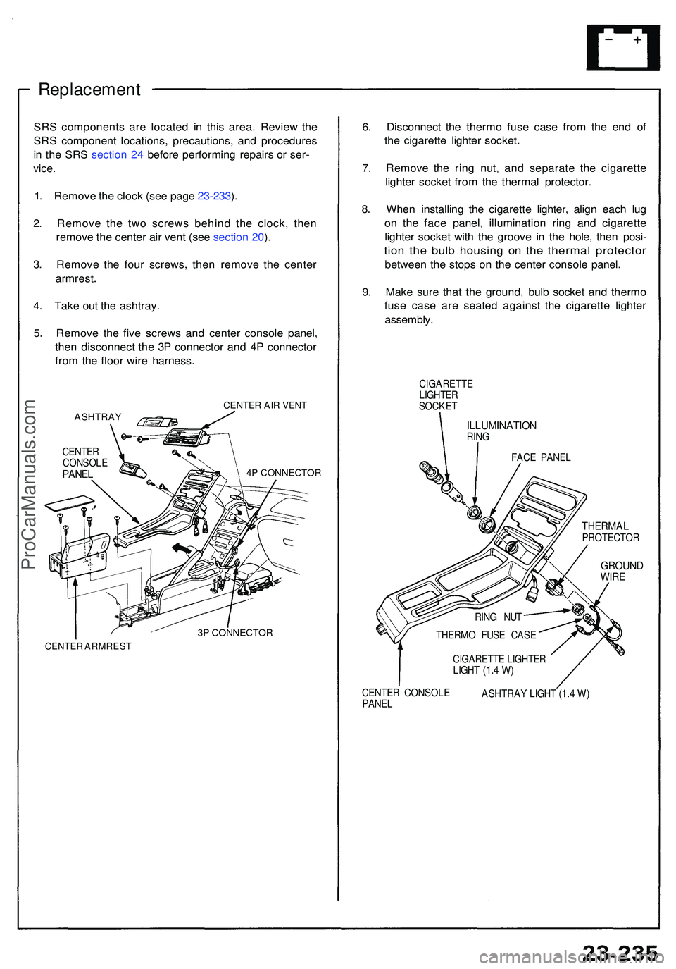
Replacement
SRS component s ar e locate d i n thi s area . Revie w th e
SR S componen t locations , precautions , an d procedure s
i n th e SR S sectio n 24 befor e performin g repair s o r ser -
vice .
1. Remov e th e cloc k (se e pag e 23-233 ).
2 . Remov e th e tw o screw s behin d th e clock , the n
remov e th e cente r ai r ven t (se e sectio n 20 ).
3 . Remov e th e fou r screws , the n remov e th e cente r
armrest .
4 . Tak e ou t th e ashtray .
5 . Remov e th e fiv e screw s an d cente r consol e panel ,
the n disconnec t th e 3 P connecto r an d 4 P connecto r
fro m th e floo r wir e harness .
ASHTRA YCENTER AIR VENT
4P CONNECTOR
3P CONNECTOR
CENTER ARMRES T
6. Disconnec t th e therm o fus e cas e fro m th e en d o f
th e cigarett e lighte r socket .
7 . Remov e th e rin g nut , an d separat e th e cigarett e
lighte r socke t fro m th e therma l protector .
8 . Whe n installin g th e cigarett e lighter , alig n eac h lu g
o n th e fac e panel , illuminatio n rin g an d cigarett e
lighte r socke t wit h th e groov e i n th e hole , the n posi -
tion th e bul b housin g o n th e therma l protecto r
between th e stop s o n th e cente r consol e panel .
9 . Mak e sur e tha t th e ground , bul b socke t an d therm o
fus e cas e ar e seate d agains t th e cigarett e lighte r
assembly .
CIGARETT E
LIGHTE R
SOCKE T
ILLUMINATIO NRING
FACE PANE L
THERMA LPROTECTO R
GROUNDWIRE
RING NU T
THERM O FUS E CAS E
CIGARETT E LIGHTE R
LIGH T (1. 4 W )
CENTE R CONSOL E
PANE L ASHTRA
Y LIGH T (1. 4 W )
CENTE
R
CONSOL E
PANEL
ProCarManuals.com
Page 1381 of 1503
1. Remov e th e glov e bo x (se e sectio n 20 ).
2 . Disconnec t th e 4 P connecto r fro m th e cigarett e
lighte r rela y (wir e color s of 4P connector : BLU /
GRN, YEL/RED , BRN/YEL , BLK) .
3. Chec k continuit y a t th e rela y terminals .
Ther e shoul d b e continuit y betwee n th e C an d D
terminals .
There shoul d b e continuit y betwee n th e A an d B
terminal s whe n powe r an d groun d ar e connecte d
t o th e C an d D terminals .
Ther e shoul d b e n o continuit y betwee n th e A
an d B terminal s whe n powe r i s disconnected .
Cigarette Lighte r
Relay Tes t
ProCarManuals.com
Page 1385 of 1503

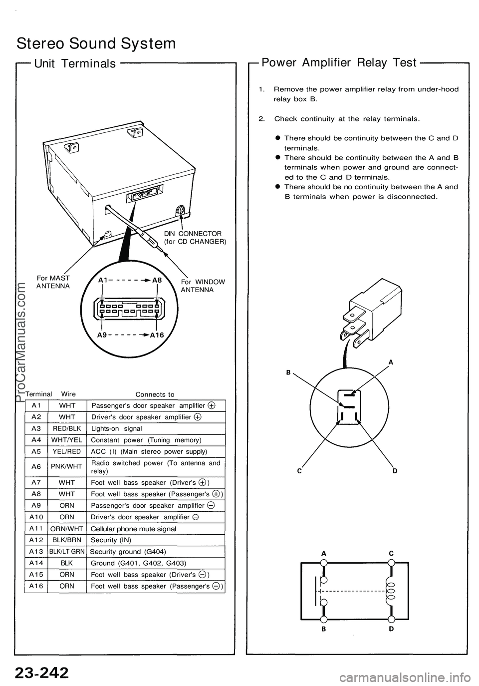
Stereo Sound System
Unit Terminals
For MAST
ANTENNA
DIN CONNECTOR
(for CD CHANGER)
For WINDOW
ANTENNA
Terminal Wire
Connects to
A1
A2
A3
A4
A5
A6
A7
A8
A9
A10
A11
A12
A13
A14
A15
A16
WHT
WHT
RED/BLK
WHT/YEL
YEL/RED
PNK/WHT
WHT
WHT
ORN
ORN
ORN/WHT
BLK/BRN
BLK/LT GRN
BLK
ORN
ORN
Passenger's door speaker amplifier
Driver's door speaker amplifier
Lights-on signal
Constant power (Tuning memory)
ACC (I) (Main stereo power supply)
Radio switched power (To antenna and
relay)
Foot well bass speaker (Driver's )
Foot well bass speaker (Passenger's )
Passenger's door speaker amplifier
Driver's door speaker amplifier
Cellular phone mute signal
Security (IN)
Security ground (G404)
Ground (G401, G402, G403)
Foot well bass speaker (Driver's )
Foot well bass speaker (Passenger's )
Power Amplifier Relay Test
1. Remove the power amplifier relay from under-hood
relay box B.
2. Check continuity at the relay terminals.
There should be continuity between the C and D
terminals.
There should be continuity between the A and B
terminals when power and ground are connect-
ed to the C and D terminals.
There should be no continuity between the A and
B terminals when power is disconnected.ProCarManuals.com
Page 1392 of 1503

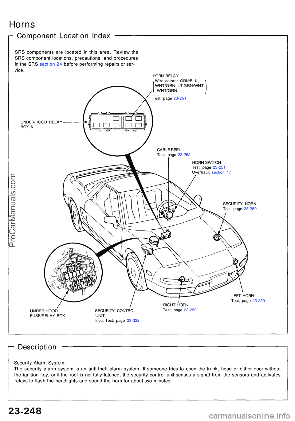
Horns
Componen t Locatio n Inde x
SRS component s ar e locate d i n thi s area . Revie w th e
SR S componen t locations , precautions , an d procedure s
i n th e SR S sectio n 24 befor e performin g repair s o r ser -
vice .
UNDER-HOO D RELA YBOX A
HOR N SWITC HTest, pag e 23-25 1
Overhaul , sectio n 1 7
CABL
E REE L
Test , pag e 23-25 2
SECURITY HOR N
Test , pag e 23-25 0
UNDER-HOO DFUSE/RELAY BO X SECURIT
Y CONTRO LUNITInpu t Test , pag e 23-32 2
RIGHT HOR NTest, pag e 23-25 0 LEF
T HOR N
Test , pag e 23-25 0
Descriptio n
Security Alar m System :
Th e securit y alar m syste m is a n anti-thef t alar m system . I f someon e trie s t o ope n th e trunk , hoo d o r eithe r doo r withou t
th e ignitio n key , o r i f th e roo f i s no t full y latched , th e securit y contro l uni t sense s a signa l fro m th e sensor s an d activate s
relay s t o flas h th e headlight s an d soun d th e hor n fo r abou t tw o minutes .
HORN RELA Y
Wir e colors : ORN/BLK ,
WHT/GRN, L T GRN/WHT ,, WHT/GR N
Test, pag e 23-25 1
ProCarManuals.com
Page 1427 of 1503
Switch Replacement (cont'd)
Rear Window Defogger
5. Disconnect the 18P and 10P connectors.
CAUTION: Be careful not to damage the SRS wire
harness.
6. Remove the six screws, then remove the rear win-
dow defogger-light switch assembly.
7. If necessary, replace the rear window defogger
switch bulbs.ProCarManuals.com