Page 753 of 1503
Deceleration Lock-up
Lock-up Control Solenoid Valve A: ON Lock-up Control Solenoid Valve B: Duty Operation
The TCM switches the solenoid valve B to ON and OFF alternately at high speeds under certain conditions.
The slight lock-up and half lock-up regions are maintained so as to lock the torque converter properly.
NOTE: When used, "left" or "right" indicates direction on the hydraulic circuit.
Lock-up System (cont'd)
DescriptionProCarManuals.com
Page 758 of 1503
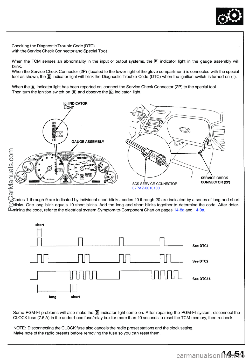
Checking th e Diagnosti c Troubl e Cod e (DTC )
wit h th e Servic e Chec k Connecto r an d Specia l Too t
Whe n th e TC M sense s a n abnormalit y i n th e inpu t o r outpu t systems , th e indicato r ligh t i n th e gaug e assembl y wil l
blink .
Whe n th e Servic e Chec k Connecto r (2P ) (locate d to th e lowe r righ t o f th e glov e compartment ) i s connecte d wit h th e specia l
tool a s shown , th e indicato r ligh t wil l blin k th e Diagnosti c Troubl e Cod e (DTC ) whe n th e ignitio n switc h is turne d o n (II) .
Whe n th e indicato r ligh t ha s bee n reporte d on , connec t th e Servic e Chec k Connecto r (2P ) t o th e specia l tool .
Then tur n th e ignitio n switc h o n (II ) an d observ e th e indicato r light .
Code s 1 throug h 9 ar e indicate d b y individua l shor t blinks , code s 1 0 throug h 2 0 ar e indicate d b y a serie s o f lon g an d shor t
blinks . On e lon g blin k equal s 1 0 shor t blinks . Ad d th e lon g an d shor t blink s together.to determine th e code . Afte r deter -
minin g th e code , refe r t o th e electrica l syste m Symptom-to-Componen t Char t o n page s 14-8a and 14-9a .
Some PGM-F I problem s wil l als o mak e th e indicato r ligh t com e on . Afte r repairin g th e PGM-F I system , disconnec t th e
CLOC K fus e (7. 5 A ) i n th e under-hoo d fuse/rela y bo x fo r mor e tha n 1 0 second s to rese t th e TC M memory , the n recheck .
NOTE : Disconnectin g th e CLOC K fus e als o cancel s th e radi o prese t station s an d th e cloc k setting .
Mak e not e o f th e radi o preset s befor e removin g th e fus e s o yo u ca n rese t them .
SCS SERVIC E CONNECTO R07PAZ-001010 0
ProCarManuals.com
Page 791 of 1503
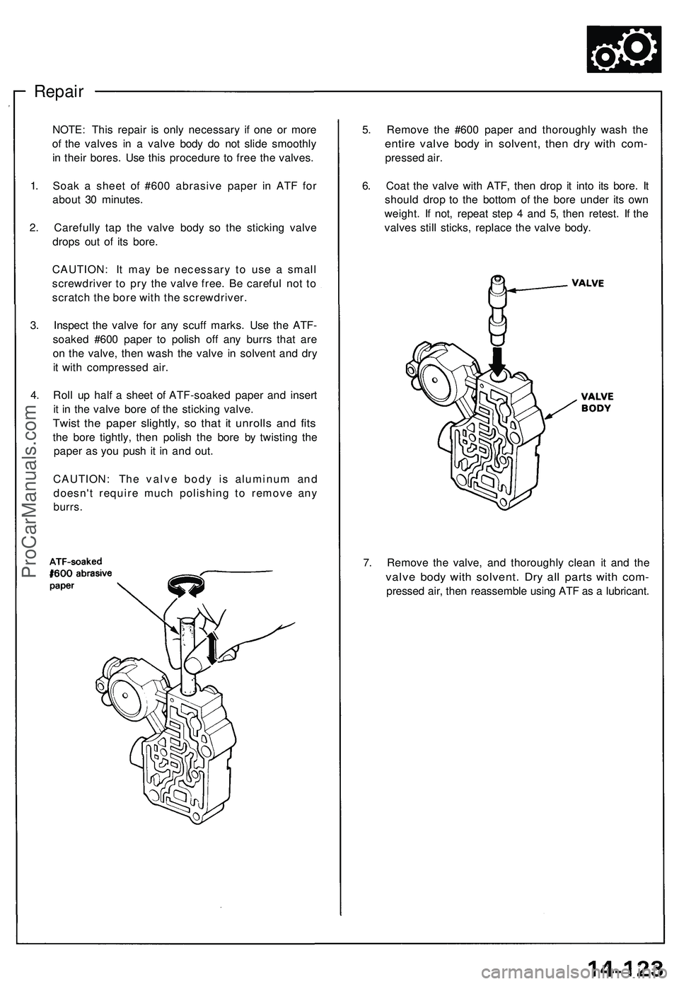
Repair
5. Remov e th e #60 0 pape r an d thoroughl y was h th e
entir e valv e bod y i n solvent , the n dr y wit h com -
presse d air .
6 . Coa t th e valv e wit h ATF , the n dro p i t int o it s bore . I t
shoul d dro p t o th e botto m o f th e bor e unde r it s ow n
weight . I f not , repea t ste p 4 an d 5 , the n retest . I f th e
valve s stil l sticks , replac e th e valv e body .
NOTE
: Thi s repai r i s onl y necessar y i f on e o r mor e
o f th e valve s i n a valv e bod y d o no t slid e smoothl y
i n thei r bores . Us e thi s procedur e t o fre e th e valves .
1 . Soa k a shee t o f #60 0 abrasiv e pape r i n AT F fo r
abou t 3 0 minutes .
2 . Carefull y ta p th e valv e bod y s o th e stickin g valv e
drop s ou t o f it s bore .
CAUTION : I t ma y b e necessar y t o us e a smal l
screwdrive r t o pr y th e valv e free . B e carefu l no t t o
scratc h th e bor e wit h th e screwdriver .
3 . Inspec t th e valv e fo r an y scuf f marks . Us e th e ATF -
soake d #60 0 pape r t o polis h of f an y burr s tha t ar e
o n th e valve , the n was h th e valv e i n solven t an d dr y
i t wit h compresse d air .
4 . Rol l u p hal f a shee t o f ATF-soake d pape r an d inser t
i t i n th e valv e bor e o f th e stickin g valve .
Twist th e pape r slightly , s o tha t i t unroll s an d fit s
the bor e tightly , the n polis h th e bor e b y twistin g th e
pape r a s yo u pus h i t i n an d out .
CAUTION : Th e valv e bod y i s aluminu m an d
doesn' t requir e muc h polishin g t o remov e an y
burrs .
7. Remov e th e valve , an d thoroughl y clea n i t an d th e
valv e bod y wit h solvent . Dr y al l part s wit h com -
presse d air , the n reassembl e usin g AT F a s a lubricant .
ProCarManuals.com
Page 836 of 1503
Installation (cont'd)
Transmission
11. Install a new set ring on the end of the left driveshaft and intermediate shaft. Apply a light film of grease around the
set ring grooves, then center the new set ring on the shafts. The grease keeps the set ring centered, making shaft
installation easier.
12. Install the left driveshaft.
13. Install the lower control arm to the side beam.
CAUTION: Line up the reference marks on the adjusting bolt, adjusting cam, and lower control arm.
14. Install the damper fork bolt.
15. Install the toe control arm to the side beam.
CAUTION: Make sure that the reference marks on the toe control arm are aligned.
16. Install the wheel sensor wire clamp and parking brake cable holder.
17. Install the intermediate shaft, and tighten the intermediate shaft mounting bolts to the intermediate shaft support
base.
18. Install the intermediate shaft heat shield cover.ProCarManuals.com
Page 884 of 1503
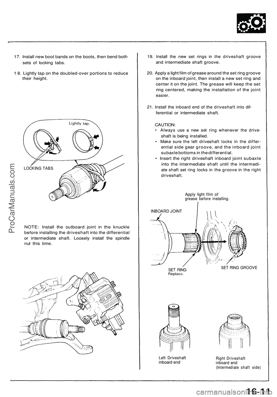
17. Install new boot bands on the boots, then bend both
sets of locking tabs.
1 8. Lightly tap on the doubled-over portions to reduce
their height.
NOTE: Install the outboard joint in the knuckle
before installing the driveshaft into the differential
or intermediate shaft. Loosely install the spindle
nut this time.
19. Install the new set rings in the driveshaft groove
and intermediate shaft groove.
20. Apply a light film of grease around the set ring groove
on the inboard joint, then install a new set ring and
center it on the joint. The grease will keep the set
ring centered, making the installation of the joint
easier.
21. Install the inboard end of the driveshaft into dif-
ferential or intermediate shaft.
CAUTION:
• Always use a new set ring whenever the drive-
shaft is being installed.
• Make sure the left driveshaft locks in the differ-
ential side gear groove, and the inboard joint
subaxle bottoms in the differential.
• Insert the right driveshaft inboard joint subaxle
into the intermediate shaft until the intermedi-
ate shaft set ring locks in the groove in the right
driveshaft.
Apply light film of
grease before installing.
INBOARD JOINT
SET RING
SET RING GROOVE
Left Driveshaft
inboard end
Right Driveshaft
inboard end
(Intermediate shaft side)
LOCKING TABSProCarManuals.com
Page 885 of 1503
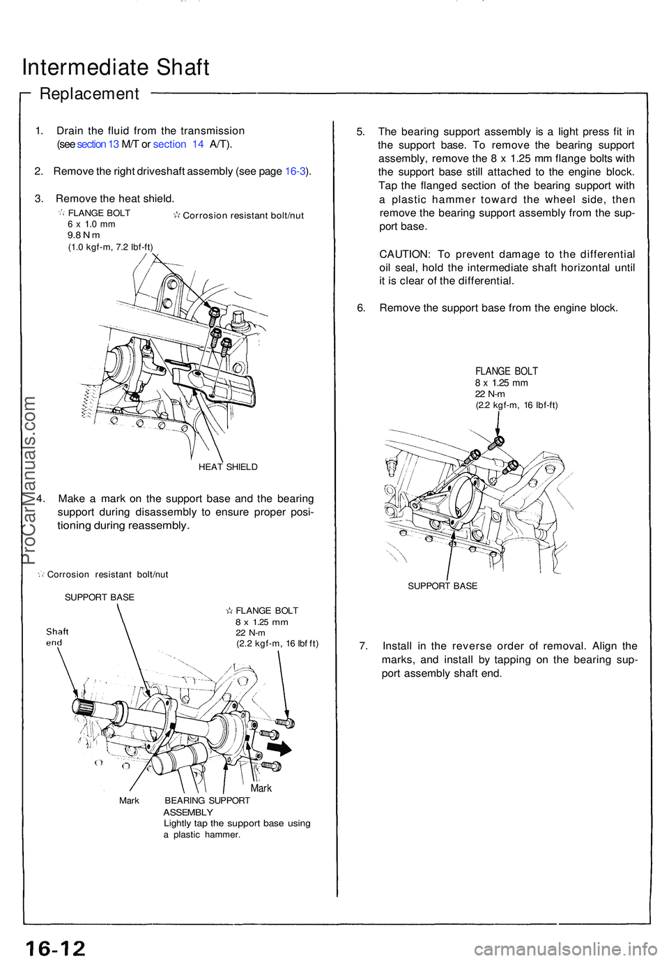
Intermediate Shaf t
Replacemen t
1. Drai n th e flui d fro m th e transmissio n
(see section 1 3 M/ T o r sectio n 14 A/T) .
2 . Remov e th e righ t driveshaf t assembl y (se e pag e 16-3 ).
3 . Remov e th e hea t shield .
HEAT SHIEL D
4. Mak e a mar k o n th e suppor t bas e an d th e bearin g
suppor t durin g disassembl y t o ensur e prope r posi -
tionin g durin g reassembly .
Corrosion resistan t bolt/nu t
SUPPOR T BAS E
MarkMark BEARIN G SUPPOR TASSEMBL YLightly ta p th e suppor t bas e usin ga plasti c hammer .
5. Th e bearin g suppor t assembl y i s a ligh t pres s fi t i n
th e suppor t base . T o remov e th e bearin g suppor t
assembly , remov e th e 8 x 1.2 5 m m flang e bolt s wit h
th e suppor t bas e stil l attache d t o th e engin e block .
Ta p th e flange d sectio n o f th e bearin g suppor t wit h
a plasti c hamme r towar d th e whee l side , the n
remov e th e bearin g suppor t assembl y fro m th e sup -
por t base .
CAUTION : T o preven t damag e t o th e differentia l
oi l seal , hol d th e intermediat e shaf t horizonta l unti l
i t i s clea r o f th e differential .
6 . Remov e th e suppor t bas e fro m th e engin e block .
FLANG E BOL T8 x 1.2 5 mm22 N- m(2.2 kgf-m , 1 6 Ibf-ft )
SUPPOR T BAS E
7. Instal l i n th e revers e orde r o f removal . Alig n th e
marks , an d instal l b y tappin g o n th e bearin g sup -
por t assembl y shaf t end .
FLANG E BOL T8 x 1.2 5 mm22 N- m(2.2 kgf-m , 1 6 Ib f ft )
Corrosio n resistan t bolt/nu tFLANGE BOL T6 x 1. 0 m m9.8 N m(1. 0 kgf-m , 7. 2 Ibf-ft )
ProCarManuals.com
Page 896 of 1503
Electrical Powe r Steerin g (EPS )
Outlin e
The NSX/NSX- T use s a n electri c motor-drive n powe r steering , whic h possesse s th e characteristic s bes t suite d fo r a mid -
engin e automobile . Thi s syste m is a power-assiste d steerin g device , wit h a moto r insid e th e steerin g gearbo x drive n b y
th e EP S contro l unit . It s distinctiv e feature s ar e describe d below :
• Minimize d los s o f engin e horsepowe r an d decrease d fue l consumption .
• A linea r steerin g fee l an d th e reductio n o f kickback .
• Th e syste m is compac t an d lightweigh t becaus e it require s n o complicate d hydrauli c piping , etc .
ProCarManuals.com
Page 902 of 1503
Self-Diagnosis Function
The EPS control unit monitors the system inputs and outputs, and the driving current of the motor. If there is a problem in
the system, the control unit turns the system off by actuating the relay. Power assist stops and normal manual steering
operation resumes. The control unit also turns the EPS indicator light on to alert the driver, and memorizes the problem in
the form of a code. Connecting the terminals of the service check connector with the SCS service connector (special tool)
enables the EPS indicator light to blink the problem code when the ignition switch is turned on (II).
Unloader Control
If the steering wheel is turned fully and held in the full-lock position, the steering torque reaches the maximum point, and
an over-current flows to the motor. The control unit detects this and reduces the current flow to the motor.
Average Moving Current Control
The electric current flow to the motor is estimated from the current values detected by the current sensor, and the average
current is obtained at two second intervals. The motor driving current is suppressed when the average current value
exceeds a predetermined marginal value. The control unit regulates the motor current during continuous loading to sup-
press any excessive temperature rise in the motor.ProCarManuals.com