Page 455 of 1503
Valves, Valv e Spring s
an d Valv e Seal s
Replacemen t
NOTE: Identif y valve s an d valv e spring s a s the y ar e
remove d s o tha t eac h ite m ca n b e reinstalle d i n it s origi -
nal position .
1. Usin g a n appropriate-size d socke t an d plasti c mallet ,
lightl y ta p th e valv e retaine r t o loose n th e valv e keep -
er s befor e installin g th e valv e sprin g compressor .
PLASTIC MALLE T
SOCKET
2. Instal l th e sprin g compressor . Compres s th e sprin g
an d remov e valv e keeper .
VALVE SPRIN GCOMPRESSO RATTACHMENTEXTENSION
07MA F - PR9010 A VALV
E SPRIN G
COMPRESSO RATTACHMENT07757 - PJ1010 A
VALV E SPRIN G COMPRESSO R
(Commercially available )Snap-on CF71 1 o r equivalen t
(cont'd)
ProCarManuals.com
Page 465 of 1503
Valve Installation
NOTE: Tap the valve stem only along its axis so you do
not bend the stem.
• When installing valves in the cylinder head, coat valve
stems with oil before inserting into valve guides, and
make sure all valves move up and down smoothly.
• When valves and springs are in place, lightly tap the
end of each valve stem two or three times to ensure
proper seating of valve and valve keepers (use ham-
mer handle bottom).
VALVE STEMS
HAMMER HANDLE
BOTTOMProCarManuals.com
Page 469 of 1503
Camshafts
Installation
CAUTION: Valve locknuts should be loosened and ad-
justing screws backed off before installation.
1. After wiping down the camshaft and journals in the
cylinder head, lubricate both surfaces and install the
camshafts and rubber caps.
NOTE: Apply liquid gasket around the rubber cap.
2. Turn the camshaft until its keyway is facing up. (No. 1
cylinder
TDC).
3. Set a new O-ring and a dowel pin in the oil passage
of the No. 1 camshaft holder.
4. Install the camshaft seals with the open side
(spring) facing in.
Lubricate cam lobes after reassembly.
O-RING
(Replace)
and
DOWEL PIN
Keyways
facing up.
CAMSHAFT SEAL
Seal housing surface should be dry.
Apply a light coat of oil to camshaft
and inner lip of seal.
RUBBER CAPS
Replace for oil
leakage.ProCarManuals.com
Page 472 of 1503

Camshafts
Installation (cont'd)
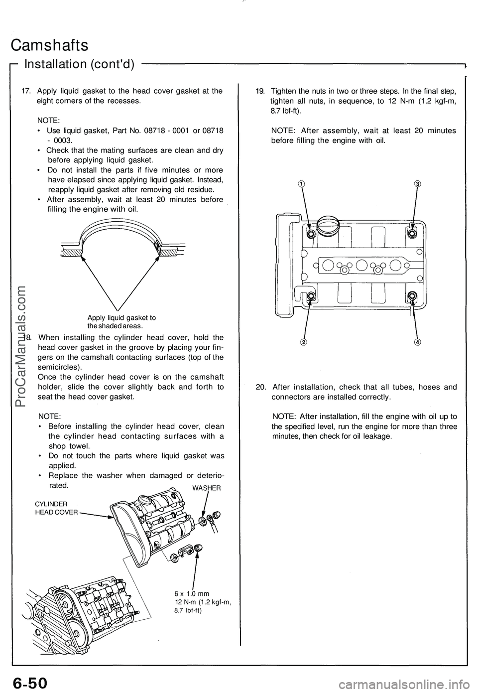
17. Apply liquid gasket to the head cover gasket at the
eight corners of the recesses.
NOTE:
• Use liquid gasket, Part No. 08718 - 0001 or 08718
- 0003.
• Check that the mating surfaces are clean and dry
before applying liquid gasket.
• Do not install the parts if five minutes or more
have elapsed since applying liquid gasket. Instead,
reapply liquid gasket after removing old residue.
• After assembly, wait at least 20 minutes before
filling the engine with oil.
Apply liquid gasket to
the shaded areas.
18. When installing the cylinder head cover, hold the
head cover gasket in the groove by placing your fin-
gers on the camshaft contacting surfaces (top of the
semicircles).
Once the cylinder head cover is on the camshaft
holder, slide the cover slightly back and forth to
seat the head cover gasket.
NOTE:
• Before installing the cylinder head cover, clean
the cylinder head contacting surfaces with a
shop towel.
• Do not touch the parts where liquid gasket was
applied.
• Replace the washer when damaged or deterio-
rated.
CYLINDER
HEAD COVER
WASHER
6 x 1.0 mm
12 N-m (1.2 kgf-m,
8.7 Ibf-ft)
19. Tighten the nuts in two or three steps. In the final step,
tighten all nuts, in sequence, to 12 N-m (1.2 kgf-m,
8.7 Ibf-ft).
NOTE: After assembly, wait at least 20 minutes
before filling the engine with oil.
20. After installation, check that all tubes, hoses and
connectors are installed correctly.
NOTE: After installation, fill the engine with oil up to
the specified level, run the engine for more than three
minutes, then check for oil leakage.ProCarManuals.com
Page 517 of 1503

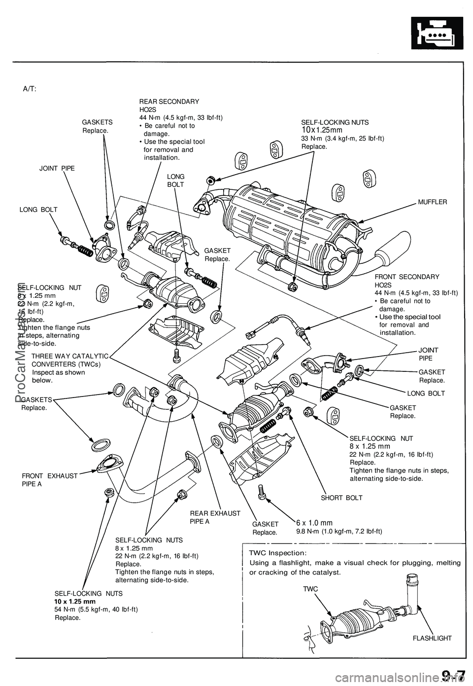
A/T:
GASKET SReplace.
REAR SECONDAR Y
HO2 S
4 4 N- m (4. 5 kgf-m , 3 3 Ibf-ft )
• B e carefu l no t t o
damage .
• Us e th e specia l too lfor remova l an dinstallation .
SELF-LOCKIN G NUT S10 x 1.2 5 m m33 N- m (3. 4 kgf-m , 2 5 Ibf-ft )Replace .
JOINT PIP E
LON G BOL T
FRON T EXHAUS T
PIP E A MUFFLE
R
SELF-LOCKIN G NU T
8 x 1.2 5 mm22 N- m (2. 2 kgf-m ,
1 6 Ibf-ft )
Replace .Tighten th e flang e nut sin steps , alternatin gside-to-side .
THREE WA Y CATALYTI C
CONVERTER S (TWCs )
Inspect a s show nbelow .
GASKET S
Replace . FRON
T SECONDAR Y
HO2 S
4 4 N- m (4. 5 kgf-m , 3 3 Ibf-ft )
• B e carefu l no t t o
damage .
• Us e th e specia l too lfor remova l an dinstallation .
JOINTPIPE
GASKE T
Replace .
LON G BOL T
GASKE T
Replace .
SELF-LOCKIN G NU T
8 x 1.2 5 m m22 N- m (2. 2 kgf-m , 1 6 Ibf-ft )Replace .Tighten th e flang e nut s i n steps ,alternatin g side-to-side .
SHORT BOL T
6 x 1. 0 m m9.8 N- m (1. 0 kgf-m , 7. 2 Ibf-ft )
SELF-LOCKIN G NUT S8 x 1.2 5 mm22 N- m (2. 2 kgf-m , 1 6 Ibf-ft )
Replace .
Tighten th e flang e nut s i n steps ,alternatin g side-to-side .
SELF-LOCKIN G NUT S
5 4 N- m (5. 5 kgf-m , 4 0 Ibf-ft )
Replace .
TWC Inspection :
Usin g a flashlight , mak e a visua l chec k fo r plugging , meltin g
o r crackin g o f th e catalyst .
TWC
FLASHLIGH T
GASKE
T
Replace .
REA
R EXHAUS T
PIP E AGASKE
T
Replace .
LON
G
BOL T
ProCarManuals.com
Page 536 of 1503
System Descriptio n
Electrical Connection s
In th e under-hoo d fuse/rela y bo x
I n th e engin e compartmen t fuse/rela y bo x
I n th e under-das h fus e bo x
FUSE SBRAK E LIGHT S HOR N (2 0 A) *
TH L MOTO R (2 0 A)* *
CLOC K (7. 5 A) *
AC G (12 0 A)* *ACG(S ) (2 0 A)* *IG COI L (3 0 A)* *
No . 2 FUE L PUM P SRS 2 (1 5 A)** *
No. 5 BACK-U P LIGHT SALTERNATO RTURN SIGNAL S (1 5 A)** »No. 7 STARTE R SIGNA L (7. 5 A)** *
ProCarManuals.com
Page 567 of 1503
CAUTION:
Puncturing the insulation on a wire can cause poor or intermittent electrical connections.
Bring the tester probe into contact with the terminal from the connector side of wire harness connectors in the engine
compartment. For female connectors, just touch lightly with the tester probe and do not insert the probe.
RUBBER SEAL
WIRE HARNESS
TERMINAL
TESTER PROBEProCarManuals.com
Page 576 of 1503

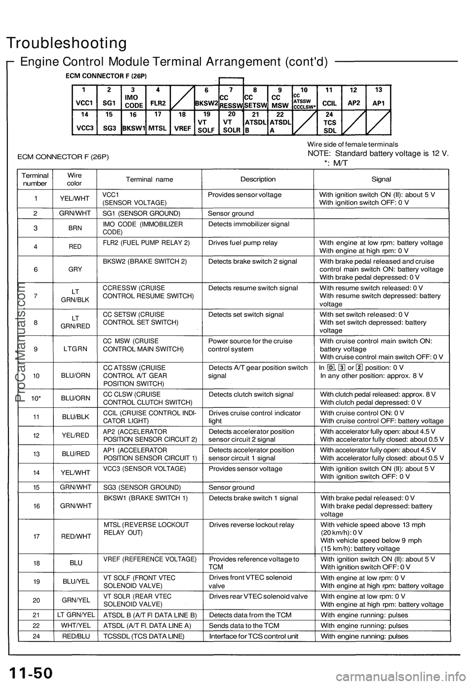
Troubleshooting
Engine Control Module Terminal Arrangement (cont'd)
ECM CONNECTOR F (26P)
Wire side of female terminals
NOTE: Standard battery voltage is 12 V.
*: M/T
Terminal
number
1
2
3
4
6
7
8
9
10
10*
11
12
13
14
15
16
17
18
19
20
21
22
24
Wire
color
YEL/WHT
GRN/WHT
BRN
RED
GRY
LT
GRN/BLK
LT
GRN/RED
LTGRN
BLU/ORN
BLU/ORN
BLU/BLK
YEL/RED
BLU/RED
YEL/WHT
GRN/WHT
GRN/WHT
RED/WHT
BLU
BLU/YEL
GRN/YEL
LT GRN/YEL
WHT/YEL
RED/BLU
Terminal name
VCC1
(SENSOR VOLTAGE)
SG1 (SENSOR GROUND)
IMO CODE (IMMOBILIZER
CODE)
FLR2 (FUEL PUMP RELAY 2)
BKSW2 (BRAKE SWITCH 2)
CCRESSW (CRUISE
CONTROL RESUME SWITCH)
CC SETSW (CRUISE
CONTROL SET SWITCH)
CC MSW (CRUISE
CONTROL MAIN SWITCH)
CC ATSSW (CRUISE
CONTROL A/T GEAR
POSITION SWITCH)
CC CLSW (CRUISE
CONTROL CLUTCH SWITCH)
CCIL (CRUISE CONTROL INDI-
CATOR LIGHT)
AP2 (ACCELERATOR
POSITION SENSOR CIRCUIT 2)
AP1 (ACCELERATOR
POSITION SENSOR CIRCUIT 1)
VCC3 (SENSOR VOLTAGE)
SG3 (SENSOR GROUND)
BKSW1 (BRAKE SWITCH 1)
MTSL (REVERSE LOCKOUT
RELAY OUT)
VREF (REFERENCE VOLTAGE)
VT SOLF (FRONT VTEC
SOLENOID VALVE)
VT SOLR (REAR VTEC
SOLENOID VALVE)
ATSDL B (A/T Fl DATA LINE B)
ATSDL (A/T Fl. DATA LINE A)
TCSSDL (TCS DATA LINE)
Description
Provides sensor voltage
Sensor ground
Detects immobilizer signal
Drives fuel pump relay
Detects brake switch 2 signal
Detects resume switch signal
Detects set switch signal
Power source for the cruise
control system
Detects A/T gear position switch
signal
Detects clutch switch signal
Drives cruise control indicator
light
Detects accelerator position
sensor circuit 2 signal
Detects accelerator position
sensor circuit 1 signal
Provides sensor voltage
Sensor ground
Detects brake switch 1 signal
Drives reverse lockout relay
Provides reference voltage to
TCM
Drives front VTEC solenoid
valve
Drives rear VTEC solenoid valve
Detects data from the TCM
Sends data to the TCM
Interface for TCS control unit
Signal
With ignition switch ON (II): about 5 V
With ignition switch OFF: 0 V
With engine at low rpm: battery voltage
With engine at high rpm: 0 V
With brake pedal released and cruise
control main switch ON: battery voltage
With brake pedal depressed: 0 V
With resume switch released: 0 V
With resume switch depressed: battery
voltage
With set switch released: 0 V
With set switch depressed: battery
voltage
With cruise control main switch ON:
battery voltage
With cruise control main switch OFF: 0 V
In , or position: 0 V
In any other position: approx. 8 V
With clutch pedal released: approx. 8 V
With clutch pedal depressed: 0 V
With cruise control ON: 0 V
With cruise control OFF: battery voltage
With accelerator fully open: about 4.5 V
With accelerator fully closed: about 0.5 V
With accelerator fully open: about 4.5 V
With accelerator fully closed: about 0.5 V
With ignition switch ON (II): about 5 V
With ignition switch OFF: 0 V
With brake pedal released: 0 V
With brake pedal depressed: battery
voltage
With vehicle speed above 13 mph
(20 km/h): 0 V
With vehicle speed below 9 mph
(15 km/h): battery voltage
With ignition switch ON (II): about 5 V
With ignition switch OFF: 0 V
With engine at low rpm: 0 V
With engine at high rpm: battery voltage
With engine at low rpm: 0 V
With engine at high rpm: battery voltage
With engine running: pulses
With engine running: pulses
With engine running: pulsesProCarManuals.com