Page 290 of 1503

Overhaul (Cont'd )
Manual Steerin g
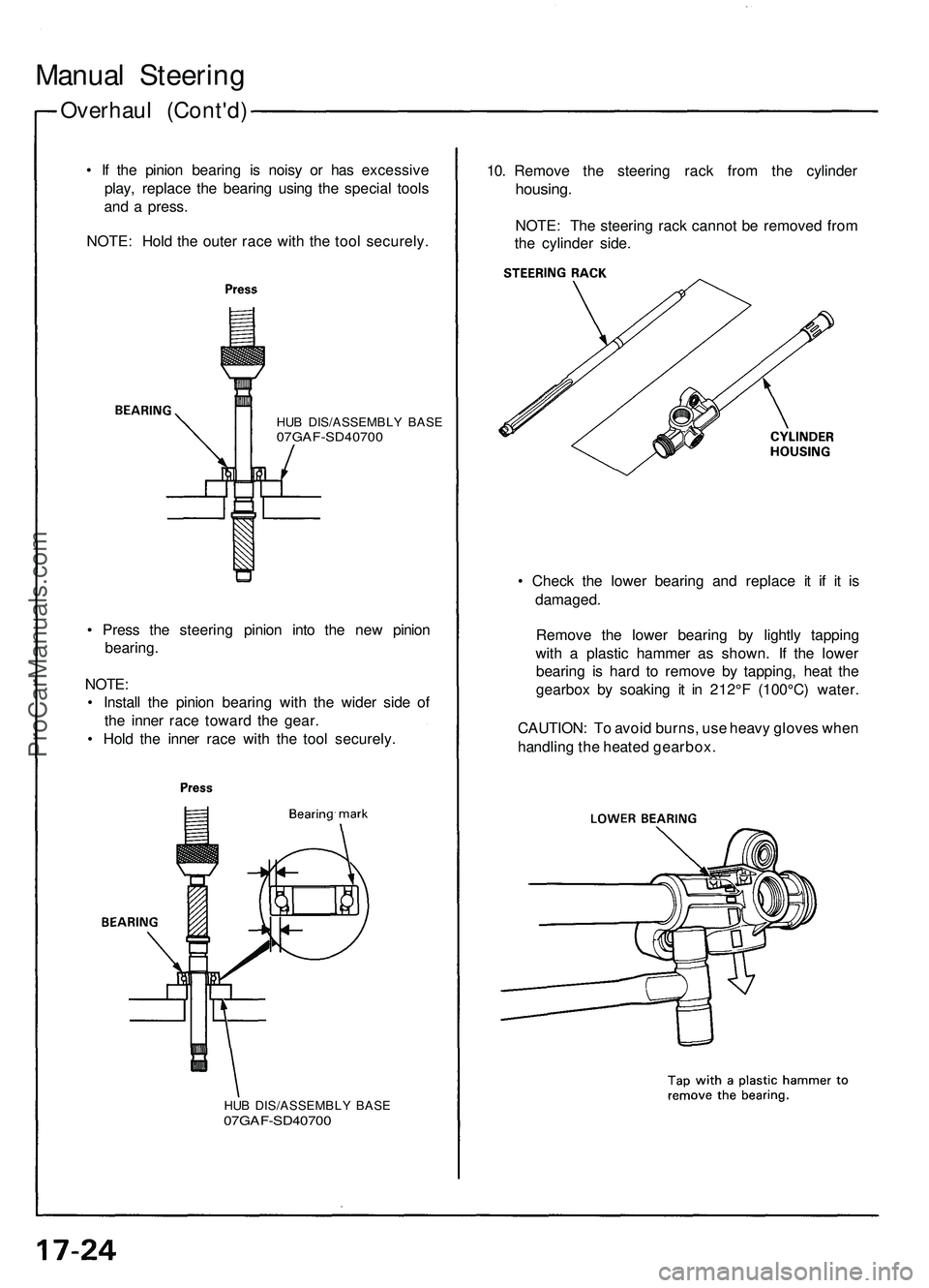
• I f th e pinio n bearin g i s nois y o r ha s excessiv e
play , replac e th e bearin g usin g th e specia l tool s
an d a press .
NOTE : Hol d th e oute r rac e wit h th e too l securely .10
. Remov e th e steerin g rac k fro m th e cylinde r
housing.
NOTE: Th e steerin g rac k canno t b e remove d fro m
th e cylinde r side .
HUB DIS/ASSEMBL Y BAS E07GAF-SD4070 0
• Chec k th e lowe r bearin g an d replac e i t i f i t i s
damaged .
Remov e th e lowe r bearin g b y lightl y tappin g
with a plasti c hamme r a s shown . I f th e lowe r
bearin g i s har d t o remov e b y tapping , hea t th e
gearbo x b y soakin g i t i n 212° F (100°C ) water .
CAUTION : T o avoi d burns , us e heav y glove s whe n
handlin g th e heate d gearbox .
•
Pres s th e steerin g pinio n int o th e ne w pinio n
bearing .
NOTE :
• Instal l th e pinio n bearin g wit h th e wide r sid e of
th e inne r rac e towar d th e gear .
• Hol d th e inne r rac e wit h th e too l securely .
HUB DIS/ASSEMBL Y BAS E07GAF-SD4070 0
ProCarManuals.com
Page 294 of 1503
29. Instal l th e ne w boo t band s o n th e boo t an d ben d bot h
set s o f lockin g tabs .
30 . Lightl y ta p o n th e double d portion s t o reduc e thei r
height .
NOTE : Afte r assembling , slid e th e rac k righ t an d lef t
t o b e certai n tha t th e boot s ar e no t deforme d o r
twisted .
32 . Instal l th e gearbo x o n th e fron t crossbea m (se e
pag e 17-20 ).
33 . Chec k th e whee l alignmen t an d adjus t i f necessar y
(se e sectio n 18 ).
31
. I f th e tie-ro d end s wer e removed , instal l th e tie -
rod s o n th e righ t an d lef t rac k end s an d scre w the m
i n unti l th e threade d sectio n i s 1 1 m m (0. 4 in ) i n
length .
ProCarManuals.com
Page 358 of 1503
Power Door Locks
Keyless Buzzer Test/Replacement
1. Open the hood.
2. Disconnect the 2P connector (A) from the keyless
buzzer (B).
3. Test the buzzer by connecting battery power to the
No. 2 terminal and grounding the No. 1 terminal.
You should hear a slight chirp.
4. If the buzzer fails to sound, remove the two mounting
screws, and replace the buzzer.ProCarManuals.com
Page 363 of 1503
Stereo Sound System
CD Changer Removal
1. Open the trunk lid.
2. Push the lock lever.
3. Remove the mounting bolt.
4. Remove the DIN cord from the CD changer.
CD CHANGER
5. Remove the CD changer bracket mounting nuts,
then remove the CD changer.
6. Install in the reverse order of removal.
NOTE: When you check a right taillight, perform bulb
check of a right taillight according to the following pro-
cedures.
1. Push the lock lever.
2. Loosing the mounting bolt.
3. Take down the CD changer.ProCarManuals.com
Page 366 of 1503
1-4
Example:
50ST (50 States) and CANADIAN
THIS VEHICLE CONFORMS TO U.S. EPA INTERIM
NON-TIER 2 BIN 9 REGULATIONS APPLICABLE TO 2005
MODEL YEAR NEW PASSENGER CARS AND CALIFORNIA
REGULATIONS APPLICABLE TO 2005 MODEL YEAR
NEW LEV I PASSENGER CARS.
Engine Family:
Model Year
5: 2005
Manufacturer
HNX: Honda
Type
V: Light Duty Vehicle/Passenger Car
Displacement
Sequence Characters
Evaporative Family:
Model Year
5: 2005
Manufacturer
HNX: Honda
Type
R: EVAP/ORVR
Canister Work Capacity (grams)
Sequence Characters
Under-hood Emissions Control Label
Emission Group Identification Engine and Evaporative Families
CJE03.2VHNX5
AAA0152RHNX5
PBY – A08
*03-NSX (61SW004)SEC01(01-04) 9/22/04 1:48 PM Page 1-4
ProCarManuals.com
Page 370 of 1503

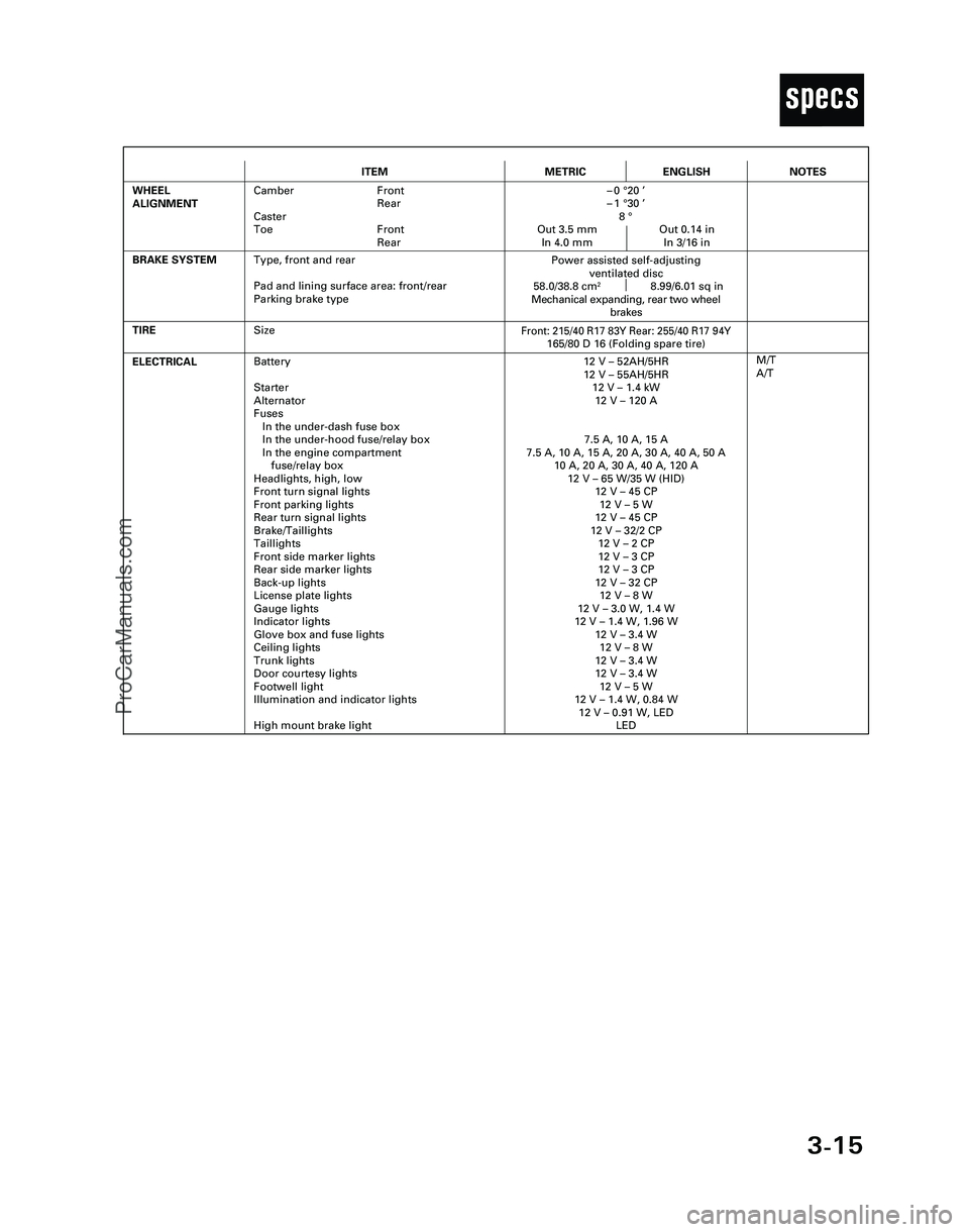
3-15
T
ITEMMETRICENGLISH
ELECTRICALBattery
Starter
Alternator
Fuses
In the under-dash fuse box
In the under-hood fuse/relay box
In the engine compartment
fuse/relay box
Headlights, high, low
Front turn signal lights
Front parking lights
Rear turn signal lights
Brake/Taillights
Taillights
Front side marker lights
Rear side marker lights
Back-up lights
License plate lights
Gauge lights
Indicator lights
Glove box and fuse lights
Ceiling lights
Trunk lights
Door courtesy lights
Footwell light
Illumination and indicator lights
High mount brake light12 V – 52AH/5HR
12 V – 55AH/5HR
12 V – 1.4 kW
12 V – 120 A
7.5 A, 10 A, 15 A
7.5 A, 10 A, 15 A, 20 A, 30 A, 40 A, 50 A
10 A, 20 A, 30 A, 40 A, 120 A
12 V – 65 W/35 W (HID)
12 V – 45 CP
12 V – 5 W
12 V – 45 CP
12 V – 32/2 CP
12 V – 2 CP
12 V – 3 CP
12 V – 3 CP
12 V – 32 CP
12 V – 8 W
12 V – 3.0 W, 1.4 W
12 V – 1.4 W, 1.96 W
12 V – 3.4 W
12 V – 8 W
12 V – 3.4 W
12 V – 3.4 W
12 V – 5 W
12 V – 1.4 W, 0.84 W
12 V – 0.91 W, LED
LED
TIRE
M/T
A/T
BRAKE SYSTEM
Front: 215/40 R17 83Y Rear: 255/40 R17 94Y165/80 D 16 (Folding spare tire)
Power assisted self-adjusting
ventilated disc
58.0/38.8 cm
28.99/6.01 sq in
Mechanical expanding, rear two wheel
brakes
WHEEL
ALIGNMENTCamber Front
Rear
Caster
Toe Front
Rear–0 °20 ’
–1 °30 ’
8 °
Out 3.5 mm Out 0.14 in
In 4.0 mm In 3/16 in
NOTES
Size
Type, front and rear
Pad and lining surface area: front/rear
Parking brake type
*04-NSX (61SW004)SEC03(01-16) 9/22/04 1:49 PM Page 3-15
ProCarManuals.com
Page 431 of 1503

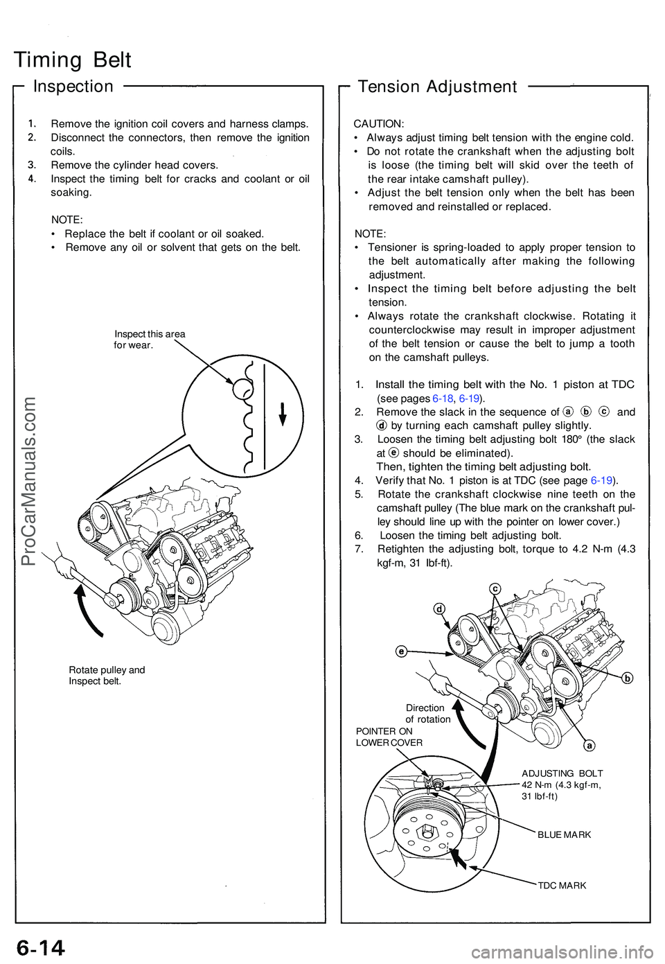
Timing Bel t
Inspectio n
Remove th e ignitio n coi l cover s an d harnes s clamps .
Disconnec t th e connectors , the n remov e th e ignitio n
coils .
Remov e th e cylinde r hea d covers .
Inspec t th e timin g bel t fo r crack s an d coolan t o r oi l
soaking .
NOTE:
• Replac e th e bel t i f coolan t o r oi l soaked .
• Remov e an y oi l o r solven t tha t get s o n th e belt .
Inspec t thi s are a
fo r wear .
Rotate pulle y an d
Inspec t belt .
Tensio n Adjustmen t
CAUTION:
• Alway s adjus t timin g bel t tensio n wit h th e engin e cold .
• D o no t rotat e th e crankshaf t whe n th e adjustin g bol t
i s loos e (th e timin g bel t wil l ski d ove r th e teet h o f
th e rea r intak e camshaf t pulley) .
• Adjus t th e bel t tensio n onl y whe n th e bel t ha s bee n
remove d an d reinstalle d o r replaced .
NOTE:
• Tensione r i s spring-loade d t o appl y prope r tensio n t o
th e bel t automaticall y afte r makin g th e followin g
adjustment .
• Inspec t th e timin g bel t befor e adjustin g th e bel t
tension .
• Alway s rotat e th e crankshaf t clockwise . Rotatin g i t
counterclockwis e ma y resul t i n imprope r adjustmen t
o f th e bel t tensio n o r caus e th e bel t t o jum p a toot h
o n th e camshaf t pulleys .
1. Instal l th e timin g bel t wit h th e No . 1 pisto n a t TD C
(see page s 6-18 , 6-19 ).
2 . Remov e th e slac k i n th e sequenc e o f an d
by turnin g eac h camshaf t pulle y slightly .
3 . Loose n th e timin g bel t adjustin g bol t 180 ° (th e slac k
at shoul d b e eliminated) .
Then, tighte n th e timin g bel t adjustin g bolt .
4. Verif y tha t No . 1 pisto n i s a t TD C (se e pag e 6-19 ).
5 . Rotat e th e crankshaf t clockwis e nin e teet h o n th e
camshaf t pulle y (Th e blu e mar k o n th e crankshaf t pul -
le y shoul d lin e u p wit h th e pointe r o n lowe r cover. )
6 . Loose n th e timin g bel t adjustin g bolt .
7 . Retighte n th e adjustin g bolt , torqu e t o 4. 2 N- m (4. 3
kgf-m , 3 1 Ibf-ft) .
Directio nof rotatio nPOINTE R O NLOWE R COVE R
ADJUSTING BOL T
42 N- m (4. 3 kgf-m ,
3 1 Ibf-ft )
BLUE MAR K
TDC MAR K
ProCarManuals.com
Page 450 of 1503
Rocker Arms and Lost Motion Assemblies
Inspection
NOTE: When reassembling the primary rocker arm, care-
fully apply air pressure to the oil passage of the rocker
arm.
PRIMARY ROCKER ARM
MID ROCKER ARM
SECONDARY
ROCKER ARM
PISTONS
1. Inspect the rocker arm pistons. Push them manually.
— If they do not move smoothly, replace the rocker
arm assembly.
PRIMARY
MID
SECONDARY
Check piston movement
NOTE:
• Apply oil to the pistons when reassembling.
• Bundle the rocker arms with rubber bands to
keep them together as sets.
2. Remove the lost motion assembly from the cylinder
head and inspect it. Pushing it gently with the finger
will cause it to sink slightly. Increasing the force on
it will cause it to sink deeper.
— If the lost motion assembly does not move
smoothly, replace it.
LOST MOTION ASSEMBLYProCarManuals.com