Page 1934 of 2890
OBD0212
L: DTC P0135
—FRONT OXYGEN SENSOR HEATER
CIRCUIT MALFUNCTION (FO2H)—
DTC DETECTING CONDITION:
�Two consecutive trips with fault
10L1Check DTC P0141 on display.
10L2Connect Subaru Select Monitor or the OBD-II
general scan tool, and read data.
10L3Check output signal from ECM. (Using voltage
meter.)
10L4Check power supply to front oxygen sensor.
10L5Check front oxygen sensor.
CAUTION:
After repair or replacement of faulty parts, conduct
CLEAR MEMORY and INSPECTION MODES.
�
�
�
�
166
2-7ON-BOARD DIAGNOSTICS II SYSTEM
10. Diagnostics Chart with Trouble Code
Page 1938 of 2890
 Turn ignition switch to OFF.
2) Connect Subaru Select Monitor or the OBD-II general
scan tool to data link")
OBD0145A
10L2CONNECT SUBARU SELECT MONITOR
OR THE OBD-II GENERAL SCAN TOOL,
AND READ DATA.
1) Turn ignition switch to OFF.
2) Connect Subaru Select Monitor or the OBD-II general
scan tool to data link connector.
3) Turn ignition switch to ON and Subaru Select Monitor or
OBD-II general scan tool switch to ON.
4) Start engine.
B2M0497
5) Read data on Subaru Select Monitor or OBD-II general
scan tool.
�Subaru Select Monitor
Designate mode using function key.
Function mode: F32
�F32: Front oxygen sensor heater current is indicated.
: Is the value more than 0.2 A in function
mode F32?
: Repair connector.
NOTE:
In this case, repair the following:
�Poor contact in front oxygen sensor connector
�Poor contact in ECM connector
: Go to step10L3.
�OBD-II scan tool
For detailed operation procedures, refer to the OBD-II Gen-
eral Scan Tool Instruction Manual.
B2M0548A
10L3CHECK OUTPUT SIGNAL FROM ECM.
(USING VOLTAGE METER.)
1) Start and idle the engine.
2) Measure voltage between ECM connector and chassis
ground.
: Connector & terminal
(B84) No. 38 (+)—Chassis ground (�):
Is the voltage less than 1.0 V?
: Go to step10L4.
: Go to next.
: Does the voltage change less than 1.0 V by
shaking harness and connector of ECM
while monitoring the value with voltage
meter?
: Repair poor contact in ECM connector.
: Go to next step 3).
170
2-7ON-BOARD DIAGNOSTICS II SYSTEM
10. Diagnostics Chart with Trouble Code
Page 1947 of 2890
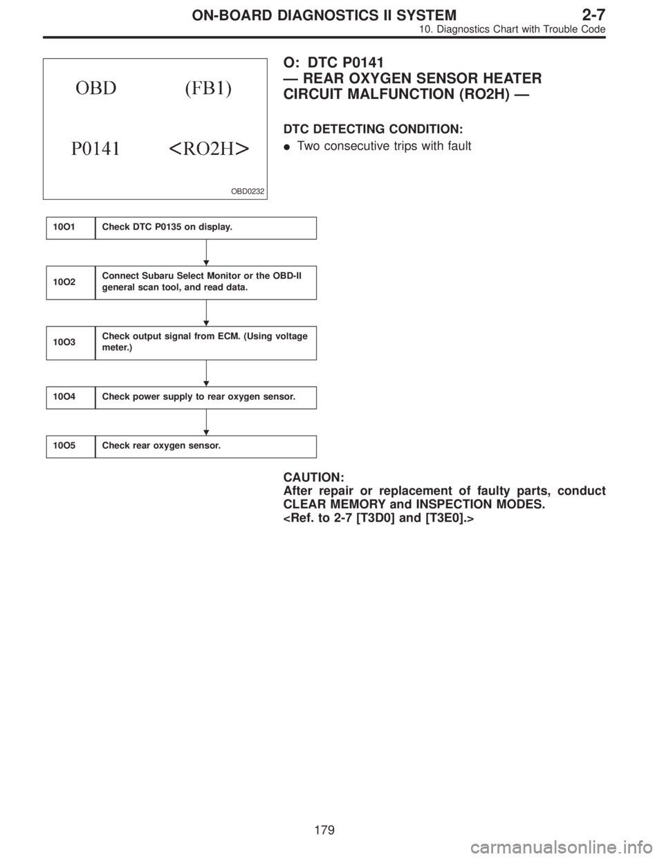
OBD0232
O: DTC P0141
—REAR OXYGEN SENSOR HEATER
CIRCUIT MALFUNCTION (RO2H)—
DTC DETECTING CONDITION:
�Two consecutive trips with fault
10O1Check DTC P0135 on display.
10O2Connect Subaru Select Monitor or the OBD-II
general scan tool, and read data.
10O3Check output signal from ECM. (Using voltage
meter.)
10O4Check power supply to rear oxygen sensor.
10O5Check rear oxygen sensor.
CAUTION:
After repair or replacement of faulty parts, conduct
CLEAR MEMORY and INSPECTION MODES.
�
�
�
�
179
2-7ON-BOARD DIAGNOSTICS II SYSTEM
10. Diagnostics Chart with Trouble Code
Page 1950 of 2890
 Turn ignition switch to OFF.
2) Disconnect connector from ECM.
3) Measure resistance of harness between ECM connec-
tor and chassis ground.
: Connector & terminal
(B84) No. 42—Chassis gr")
B2M0553A
1) Turn ignition switch to OFF.
2) Disconnect connector from ECM.
3) Measure resistance of harness between ECM connec-
tor and chassis ground.
: Connector & terminal
(B84) No. 42—Chassis ground:
Is the resistance less than 5Ω?
: Repair poor contact in ECM connector.
: Repair harness and connector.
NOTE:
In this case, repair the following:
�Open circuit in harness between ECM and coupling con-
nector (B22)
�Open circuit in harness between coupling connector
(B22) and engine grounding terminal
�Poor contact in rear oxygen sensor connector
�Poor contact in rear oxygen sensor connecting harness
connector (B19)
�Poor contact in coupling connector (B22)
OBD0145A
10O2CONNECT SUBARU SELECT MONITOR
OR THE OBD-II GENERAL SCAN TOOL,
AND READ DATA.
1) Turn ignition switch to OFF.
2) Connect Subaru Select Monitor or the OBD-II general
scan tool to data link connector.
3) Turn ignition switch to ON and Subaru Select Monitor or
OBD-II general scan tool switch to ON.
4) Start engine.
B2M0498
5) Read data on Subaru Select Monitor or OBD-II general
scan tool.
�Subaru Select Monitor
Designate mode using function key.
Function mode: F33
�F33: Rear oxygen sensor heater current is indicated.
: Is the value more than 0.2 A in function
mode F33?
: Repair connector.
NOTE:
In this case, repair the following:
�Poor contact in rear oxygen sensor connector
�Poor contact in rear oxygen sensor connecting harness
connector
�Poor contact in ECM connector
: Go to step10O3.
�OBD-II scan tool
For detailed operation procedures, refer to the OBD-II Gen-
eral Scan Tool Instruction Manual.
182
2-7ON-BOARD DIAGNOSTICS II SYSTEM
10. Diagnostics Chart with Trouble Code
Page 2227 of 2890

C: INSPECTION MODE
The on-board diagnosis system is designed to detect prob-
lems while the vehicle is being driven. If a problem is found,
the ABS and TCS warning light will illuminate to inform the
driver of the occurrence of a problem. When the warning
light is on, the ABS/TCS system will be inactive and the
normal braking function will work. It is possible for the most
recent trouble code and history of problem to be stored in
memory until cleared.
B4M0082C
D: TROUBLE CODES
When on-board diagnosis of the ABS/TCS control module
detects a problem, the information will be stored in the EEP
ROM as a trouble code. (Stored codes will stay in memory
until they are cleared.)
1. CALLING UP A TROUBLE CODE
1) Take out diagnosis connector from side of driver’s seat
heater unit.
2) Turn ignition switch OFF.
3) Connect diagnosis connector terminal No. 4 to diagno-
sis terminal.
4) Turn ignition switch ON.
5) TCS warning light is set in the diagnostic mode and
blinks to identify trouble code.
6) After the start code (11) is shown, the trouble codes will
be shown in order of the last information first.
NOTE:
When there are no trouble codes in memory, only the start
code (11) is shown.
B4M0383A
16
4-4bBRAKES
6. Diagnostics Chart for On-board Diagnosis System
Page 2352 of 2890

for at least one minute.
B4M0082D
D: TROUBL")
C: INSPECTION MODE
Reproduce the condition under which the problem has
occurred as much as possible.
Drive the vehicle at a speed more than 40 km/h (25 MPH)
for at least one minute.
B4M0082D
D: TROUBLE CODES
When on-board diagnosis of the ABS control module
detects a problem, the information (up to a maximum of
three) will be stored in the EEP ROM as a trouble code.
When there are more than three, the most recent three will
be stored. (Stored codes will stay in memory until they are
cleared.)
1. CALLING UP A TROUBLE CODE
1) Take out diagnosis connector from side of driver’s seat
heater unit.
2) Turn ignition switch OFF.
3) Connect diagnosis connector terminal 6 to diagnosis
terminal.
4) Turn ignition switch ON.
5) ABS warning light is set in the diagnostic mode and
blinks to identify trouble code.
6) After the start code (11) is shown, the trouble codes will
be shown in order of the last information first.
These repeat for a maximum of 5 minutes.
NOTE:
When there are no trouble codes in memory, only the start
code (11) is shown.
B4M0232A
12
4-4cBRAKES [ABS 5.3 TYPE]
6. Diagnostics Chart for On-board Diagnosis System
Page 2750 of 2890

MB-2 Power window circuit breaker
MB-3Engine control module
Fuel pump relay
Main relay
OBD-II service connector
MB-4 A/C relay holder
MB-5 He")
No. Load
MB-1Fuse holder (Rear power supply & seat
heater)
MB-2 Power window circuit breaker
MB-3Engine control module
Fuel pump relay
Main relay
OBD-II service connector
MB-4 A/C relay holder
MB-5 Headlight alarm relay (with security)
MB-6 Headlight LH
MB-7Daytime running light control module
Diode (Lighting)
Diode (Security)
Lighting switch
MB-8Combination meter
Front fog light switch
Headlight RH
Front fog light relay
MB-9Door lock timer
Headlight alarm relay
Interrupt relay
Radio
Security control module
Security indicator light
Spot light
Room light
Step light
Combination meter
Luggage room light
Trailer connector
Trunk room light
MB-10 A/C relay holder
SBF-6ABS relay box
TCS motor relay
SBF-7 TCS valve relay
ALT-1Combination meter
Daytime running light control module
Diode (TCS)
IG Headlight alarm relay
STCruise control module
Engine control module
Inhibitor switch (AT)
Interrupt relay
Starter interlock relay (MT)
FB-1Front washer motor
Rear washer motor
FB-2 Diode (A/C)
FB-3A/C relay holder
Sub fan motor
FB-4Engine control module
Fuel pump relay
Ignition coil
Transmission control module
FB-5 ABS relay boxNo. Load
FB-6Side marker light LH
Side marker light RH
FB-7 Door lock timer
FB-9 Hazard switch
FB-10AT shift lock control module
Key warning switch
Power antenna
FB-11 Radio
FB-12 Cigarette lighter socket
FB-13Mirror heater
Rear power supply relay
Remote control rearview mirror switch
Security control module
Vanity mirror illumination light
FB-14AT shift lock control module
Combination switch
Front wiper motor
Rear wiper motor
Rear wiper relay
FB-15ABS/TCS control module
Transmission control module
FB-16Rear defogger
Rear defogger condenser
Rear defogger switch
FB-17 Rear defogger switch
FB-18AT shift lock control module
Back-up light switch (MT)
Inhibitor switch (AT)
FB-19 Hazard switch
FB-20A/C switch
Combination meter
Mode control panel
TCS off switch
FB-21 Combination meter (Airbag)
FB-22Blower motor relay
Check connector
Daytime running light control module
Daytime running light relay
FRESH/RECIRC actuator
Hi-beam relay
Power window and sunroof relay
Seat belt timer
FB-23 Airbag control module
20
6-3WIRING DIAGRAM
6. Wiring Diagram
Page 2836 of 2890
36. SEAT HEATER SYSTEM
BU84-02
106
6-3WIRING DIAGRAM
6. Wiring Diagram