Page 1324 of 2890
 Under the ABS sequence control, after the hydraulic
unit solenoid valve is driven, the operation of the hydraulic
unit can be checked by means of the brake tester or pres-
s")
D: ABS SEQUENCE CONTROL
1) Under the ABS sequence control, after the hydraulic
unit solenoid valve is driven, the operation of the hydraulic
unit can be checked by means of the brake tester or pres-
sure gauge.
2) ABS sequence control can be started by diagnosis con-
nector or select monitor.
B4M0082D
1. OPERATIONAL GUIDELINES OF THE ABS
SEQUENCE CONTROL WITH DIAGNOSIS
CONNECTOR
1) Connect diagnosis terminals to terminals No. 3 and No.
6 of the diagnosis connector beside driver’s seat heater
unit.
2) Set the speed of all wheels at 4 km/h (2 MPH) or less.
3) Turn ignition switch OFF.
4) Within 0.5 seconds after the ABS warning light goes
out, depress the brake pedal and hold it immediately after
ignition switch is turned to ON.
CAUTION:
Do not depress the clutch pedal.
NOTE:
�When the ignition switch is set to on, the brake pedal
must not be depressed.
�Engine must not operate.
5) After completion of ABS sequence control, turn ignition
switch OFF.
2. OPERATIONAL GUIDELINES OF THE ABS
SEQUENCE CONTROL WITH SELECT MONITOR
1) Connect select monitor to data link connector beside
driver’s seat heater unit.
2) Turn ignition switch ON.
3) Put select monitor to ABS mode.
B4M0635
4) PressFD1ENTkey.
11 4
4-4SERVICE PROCEDURE
22. Hydraulic Unit for ABS System (ABS 5.3 Type)
Page 1355 of 2890
 or more ...
When 300 m
3(10,593 cu ft)/h�Mode
selector
switch:")
1. Heater System
A: SPECIFICATIONS
ItemSpecifications
Condition
LHD model RHD model
Heating capacity4.652 kW (4,000 kcal/h, 15,872 BTU/h) or more ...
When 300 m
3(10,593 cu ft)/h�Mode
selector
switch: HEAT
�Te m p .
control
lever: FULL HOT
�Temperature
difference
between
hot water
and inlet air:65°C
(149°F)
�Hot water
flow rate: 360�(95.1
US gal, 79.2
Imp gal)/h
Air flow rate 300 m
3(10,593 cu ft)/h 280 m3(9,887 cu ft)/hHeat mode (FRESH), FULL
HOT at 12.5 V
Max air flow rate 510 m
3(18,008 cu ft)/h 480 m3(16,949 cu ft)/h�Temperature
control
lever: FULL COLD
�Blower fan
speed: 4th position
�RECIRC
switch
position: RECIRC
Heater core size
(height x length x width x
thickness)193.5 x 152.0 x 25.0 x 0.9 mm
(7.62 x 5.98 x 0.984 x 0.035 in)159.5 x 180 x 32.0 x 1.0 mm
(6.28 x 7.09 x 1.26 x 0.039 in)—
Blower
motorType Magnet motor 230 W or less Magnet motor 220 W or less at 12 V
Fan type and size
(diameter x width)Sirocco fan type
150 x 75 mm (5.91 x 2.95 in)Sirocco fan type
140 x 65 mm (5.51 x 2.56 in)—
2
4-6SPECIFICATIONS AND SERVICE DATA
1. Heater System
Page 1356 of 2890
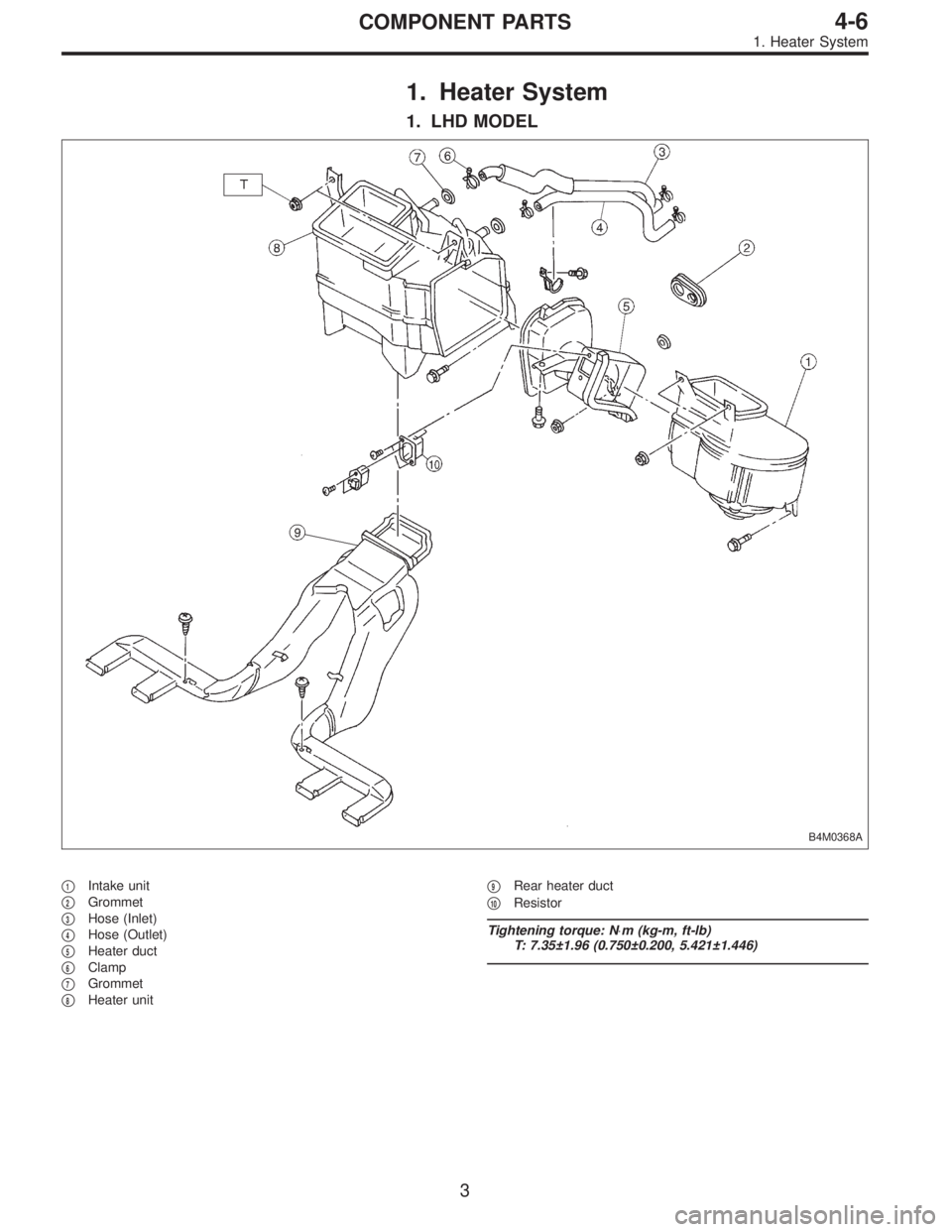
1. Heater System
1. LHD MODEL
B4M0368A
�1Intake unit
�
2Grommet
�
3Hose (Inlet)
�
4Hose (Outlet)
�
5Heater duct
�
6Clamp
�
7Grommet
�
8Heater unit�
9Rear heater duct
�
10Resistor
Tightening torque: N⋅m (kg-m, ft-lb)
T: 7.35±1.96 (0.750±0.200, 5.421±1.446)
3
4-6COMPONENT PARTS
1. Heater System
Page 1357 of 2890
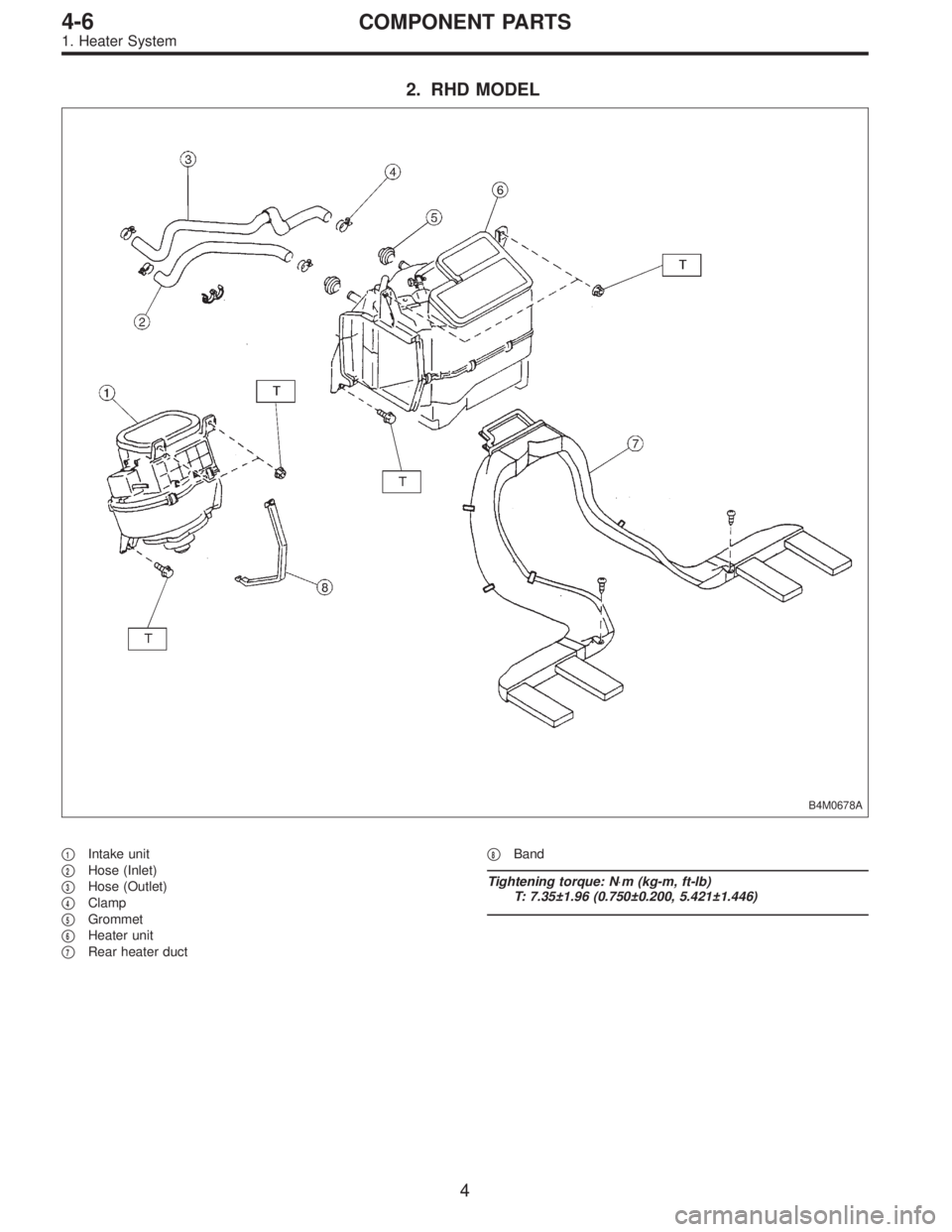
2. RHD MODEL
B4M0678A
�1Intake unit
�
2Hose (Inlet)
�
3Hose (Outlet)
�
4Clamp
�
5Grommet
�
6Heater unit
�
7Rear heater duct�
8Band
Tightening torque: N⋅m (kg-m, ft-lb)
T: 7.35±1.96 (0.750±0.200, 5.421±1.446)
4
4-6COMPONENT PARTS
1. Heater System
Page 1358 of 2890
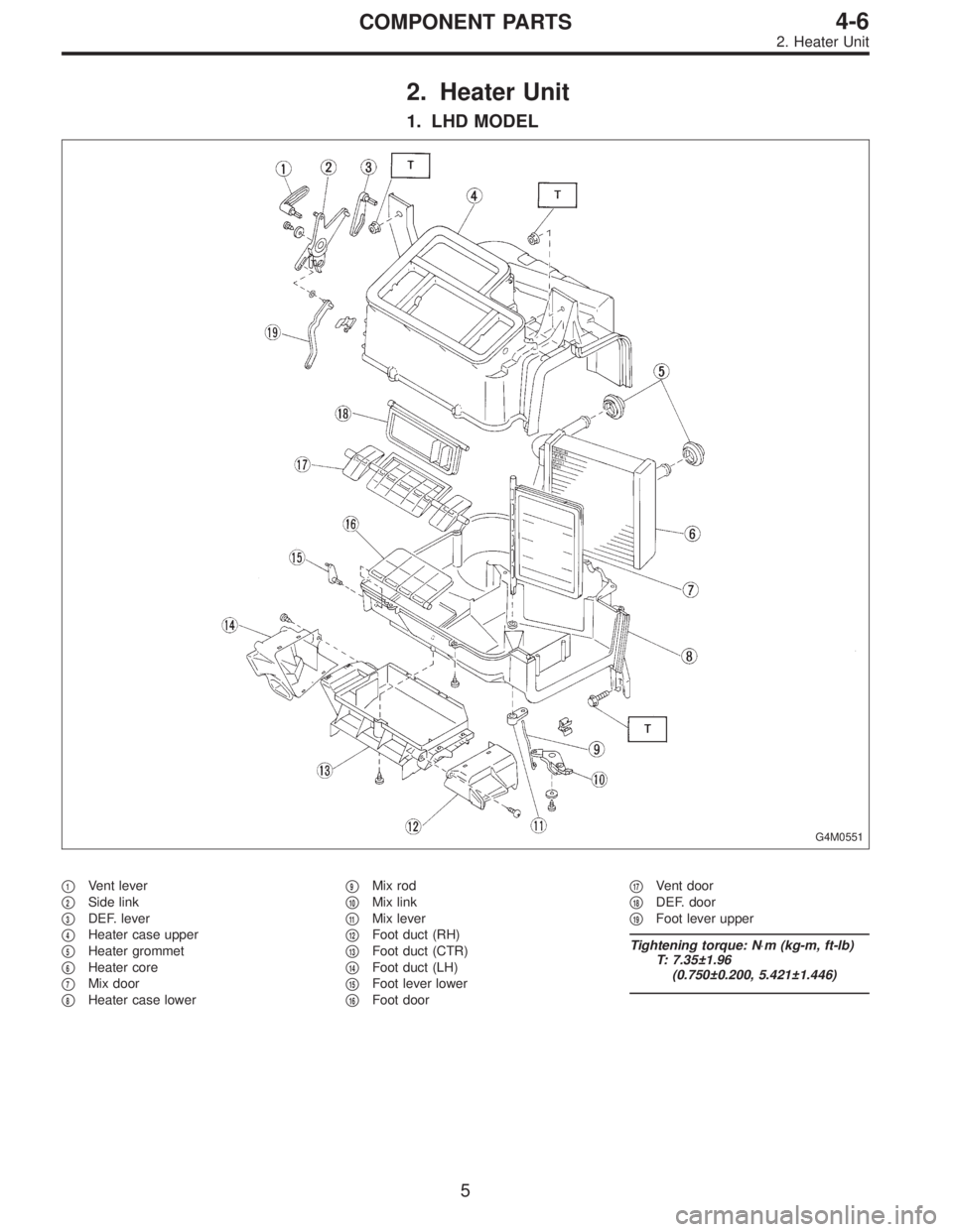
2. Heater Unit
1. LHD MODEL
G4M0551
�1Vent lever
�
2Side link
�
3DEF. lever
�
4Heater case upper
�
5Heater grommet
�
6Heater core
�
7Mix door
�
8Heater case lower�
9Mix rod
�
10Mix link
�
11Mix lever
�
12Foot duct (RH)
�
13Foot duct (CTR)
�
14Foot duct (LH)
�
15Foot lever lower
�
16Foot door�
17Vent door
�
18DEF. door
�
19Foot lever upper
Tightening torque: N⋅m (kg-m, ft-lb)
T: 7.35±1.96
(0.750±0.200, 5.421±1.446)
5
4-6COMPONENT PARTS
2. Heater Unit
Page 1359 of 2890
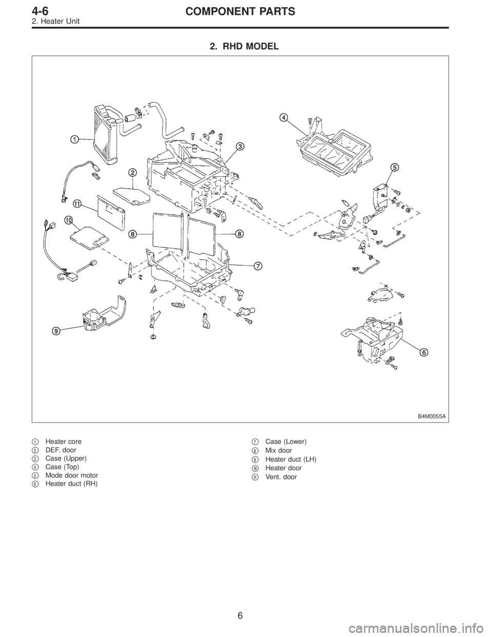
2. RHD MODEL
B4M0055A
�1Heater core
�
2DEF. door
�
3Case (Upper)
�
4Case (Top)
�
5Mode door motor
�
6Heater duct (RH)�
7Case (Lower)
�
8Mix door
�
9Heater duct (LH)
�
10Heater door
�
11Vent. door
6
4-6COMPONENT PARTS
2. Heater Unit
Page 1364 of 2890
1. Supplemental Restraint System
“Airbag”
Airbag system wiring harness is routed near the instrument
panel, heater unit, blower motor and control unit.
CAUTION:
�All Airbag system wiring harness and connectors
are colored yellow. Do not use electrical test equip-
ment on these circuit.
�Be careful not to damage Airbag system wiring har-
ness when servicing the instrument panel, heater unit,
blower motor and control unit.
2. Heater Unit
A: REMOVAL AND INSTALLATION
1) Disconnect GND cable from battery.
2) Remove heater hoses (inlet, outlet) in engine compart-
ment.
NOTE:
Drain as much coolant from heater unit as possible, and
plug disconnected hose with cloth.
3) Remove instrument panel.
4) Remove steering support beam.
5) Remove evaporator. (With A/C model)
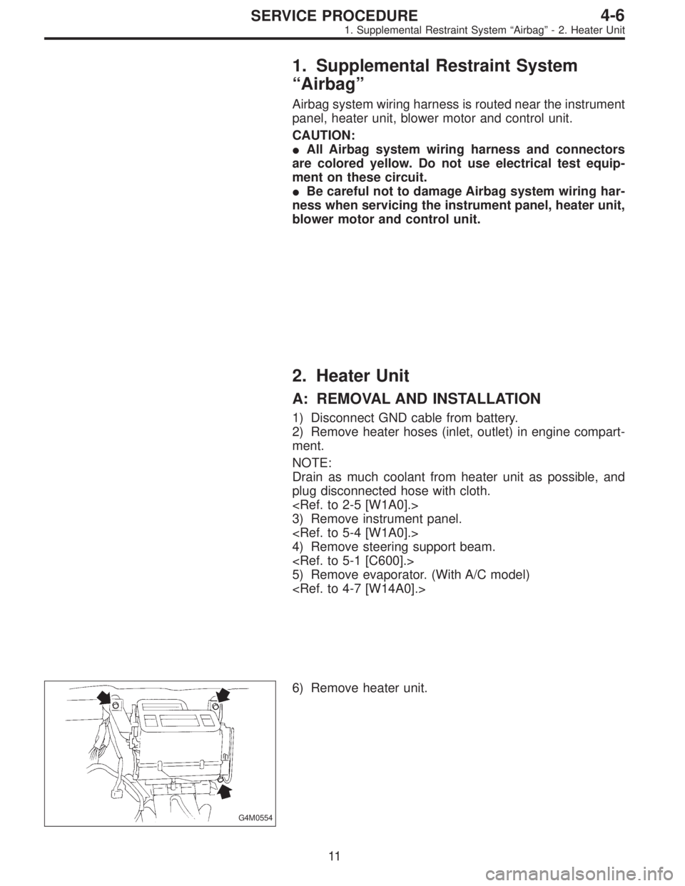
G4M0554
6) Remove heater unit.
11
4-6SERVICE PROCEDURE
1. Supplemental Restraint System“Airbag”- 2. Heater Unit
Page 1365 of 2890
1. Supplemental Restraint System
“Airbag”
Airbag system wiring harness is routed near the instrument
panel, heater unit, blower motor and control unit.
CAUTION:
�All Airbag system wiring harness and connectors
are colored yellow. Do not use electrical test equip-
ment on these circuit.
�Be careful not to damage Airbag system wiring har-
ness when servicing the instrument panel, heater unit,
blower motor and control unit.
2. Heater Unit
A: REMOVAL AND INSTALLATION
1) Disconnect GND cable from battery.
2) Remove heater hoses (inlet, outlet) in engine compart-
ment.
NOTE:
Drain as much coolant from heater unit as possible, and
plug disconnected hose with cloth.
3) Remove instrument panel.
4) Remove steering support beam.
5) Remove evaporator. (With A/C model)
G4M0554
6) Remove heater unit.
11
4-6SERVICE PROCEDURE
1. Supplemental Restraint System“Airbag”- 2. Heater Unit