Page 1366 of 2890
7) Installation is in the reverse order of removal.
Fitted length of heater hose over pipe:
25 — 30 mm (0.98 — 1.18 in)
8) Pour coolant.
B5M0025
3. Blower Motor Assembly
A: REMOVAL AND INSTALLATION
1) Disconnect GND cable from battery.
2) Remove glove box and pocket back panel.
[W1A0].>
3) Disconnect blower motor harness connector.
G4M0555
4) Disconnect aspirator pipe�1.
5) Remove blower motor mounting screw.
6) Remove blower motor assembly.
7) Installation is in the reverse order of removal.
12
4-6SERVICE PROCEDURE
2. Heater Unit - 3. Blower Motor Assembly
Page 1367 of 2890
7) Installation is in the reverse order of removal.
Fitted length of heater hose over pipe:
25 — 30 mm (0.98 — 1.18 in)
8) Pour coolant.
B5M0025
3. Blower Motor Assembly
A: REMOVAL AND INSTALLATION
1) Disconnect GND cable from battery.
2) Remove glove box and pocket back panel.
[W1A0].>
3) Disconnect blower motor harness connector.
G4M0555
4) Disconnect aspirator pipe�1.
5) Remove blower motor mounting screw.
6) Remove blower motor assembly.
7) Installation is in the reverse order of removal.
12
4-6SERVICE PROCEDURE
2. Heater Unit - 3. Blower Motor Assembly
Page 1368 of 2890
B5M0027
4. Control Unit
A: REMOVAL
1) Disconnect GND cable from battery.
2) Set temperature control lever to“FULL COLD”position.
3) Remove temperature control cable from heater unit.
NOTE:
Do not attempt to move link of heater unit during installa-
tion.
B4M0370
4) Remove cup holder.
5) Remove center panel and then disconnect connector.
B4M0059
6) Remove control unit assembly and disconnect connec-
tor.
B4M0060A
B: INSPECTION
1. FAN SWITCH
Check continuity between terminals at each switch posi-
tion.
LHD model
Switch
positionTerminals
123456
1��
�
2���
3���
4���
GND IGN
13
4-6SERVICE PROCEDURE
4. Control Unit
Page 1371 of 2890
B5M0025
5. Intake Door Motor
A: REMOVAL
1) Disconnect GND cable from battery.
2) Remove glove box and pocket back panel.
[W1A0].>
3) Remove heater duct or evaporator. (With A/C model).
G4M0561
4) Remove intake unit from the vehicle.
G4M0562
5) Remove screws which secure intake door motor to
intake unit.
NOTE:
Ensure that RECIRC switch is set to“ON”.
B4M0294A
B: INSPECTION
1) When approx. 12 V is applied to the intake door motor
terminals, intake door motor operates as follows:
LHD model
Intake
door motor
positionTerminal
Intake door motor operation
��
FRESH
32 Door motor moved to FRESH position.
RECIRC 1 Door motor moved to RECIRC position.
RHD model
Intake
door motor
positionTerminal
Intake door motor operation
��
FRESH
21 Door motor moved to FRESH position.
RECIRC 3 Door motor moved to RECIRC position.
16
4-6SERVICE PROCEDURE
5. Intake Door Motor
Page 1477 of 2890

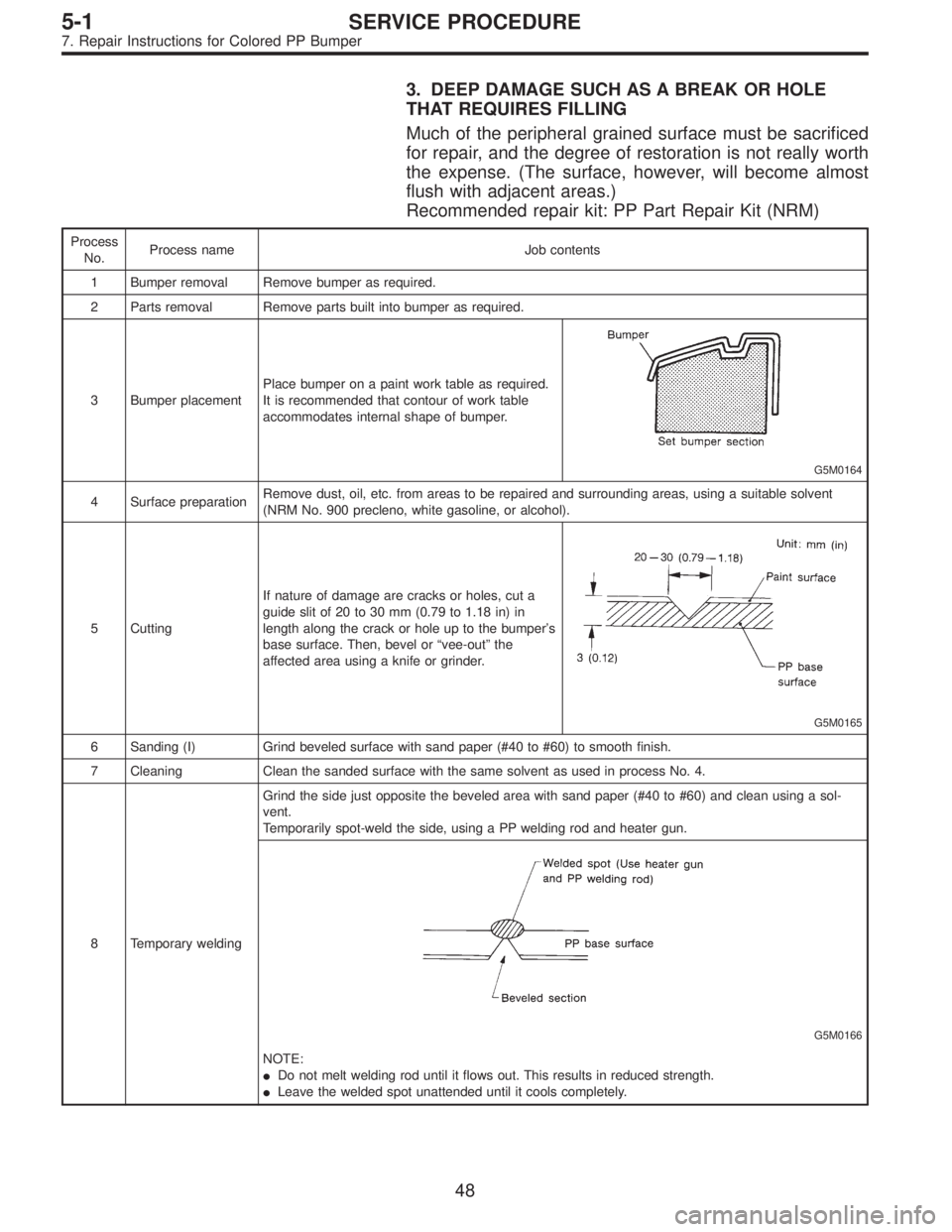
3. DEEP DAMAGE SUCH AS A BREAK OR HOLE
THAT REQUIRES FILLING
Much of the peripheral grained surface must be sacrificed
for repair, and the degree of restoration is not really worth
the expense. (The surface, however, will become almost
flush with adjacent areas.)
Recommended repair kit: PP Part Repair Kit (NRM)
Process
No.Process name Job contents
1 Bumper removal Remove bumper as required.
2 Parts removal Remove parts built into bumper as required.
3 Bumper placementPlace bumper on a paint work table as required.
It is recommended that contour of work table
accommodates internal shape of bumper.
G5M0164
4 Surface preparationRemove dust, oil, etc. from areas to be repaired and surrounding areas, using a suitable solvent
(NRM No. 900 precleno, white gasoline, or alcohol).
5 CuttingIf nature of damage are cracks or holes, cut a
guide slit of 20 to 30 mm (0.79 to 1.18 in) in
length along the crack or hole up to the bumper’s
base surface. Then, bevel or“vee-out”the
affected area using a knife or grinder.
G5M0165
6 Sanding (I) Grind beveled surface with sand paper (#40 to #60) to smooth finish.
7 Cleaning Clean the sanded surface with the same solvent as used in process No. 4.
8 Temporary weldingGrind the side just opposite the beveled area with sand paper (#40 to #60) and clean using a sol-
vent.
Temporarily spot-weld the side, using a PP welding rod and heater gun.
G5M0166
NOTE:
�Do not melt welding rod until it flows out. This results in reduced strength.
�Leave the welded spot unattended until it cools completely.
48
5-1SERVICE PROCEDURE
7. Repair Instructions for Colored PP Bumper
Page 1478 of 2890

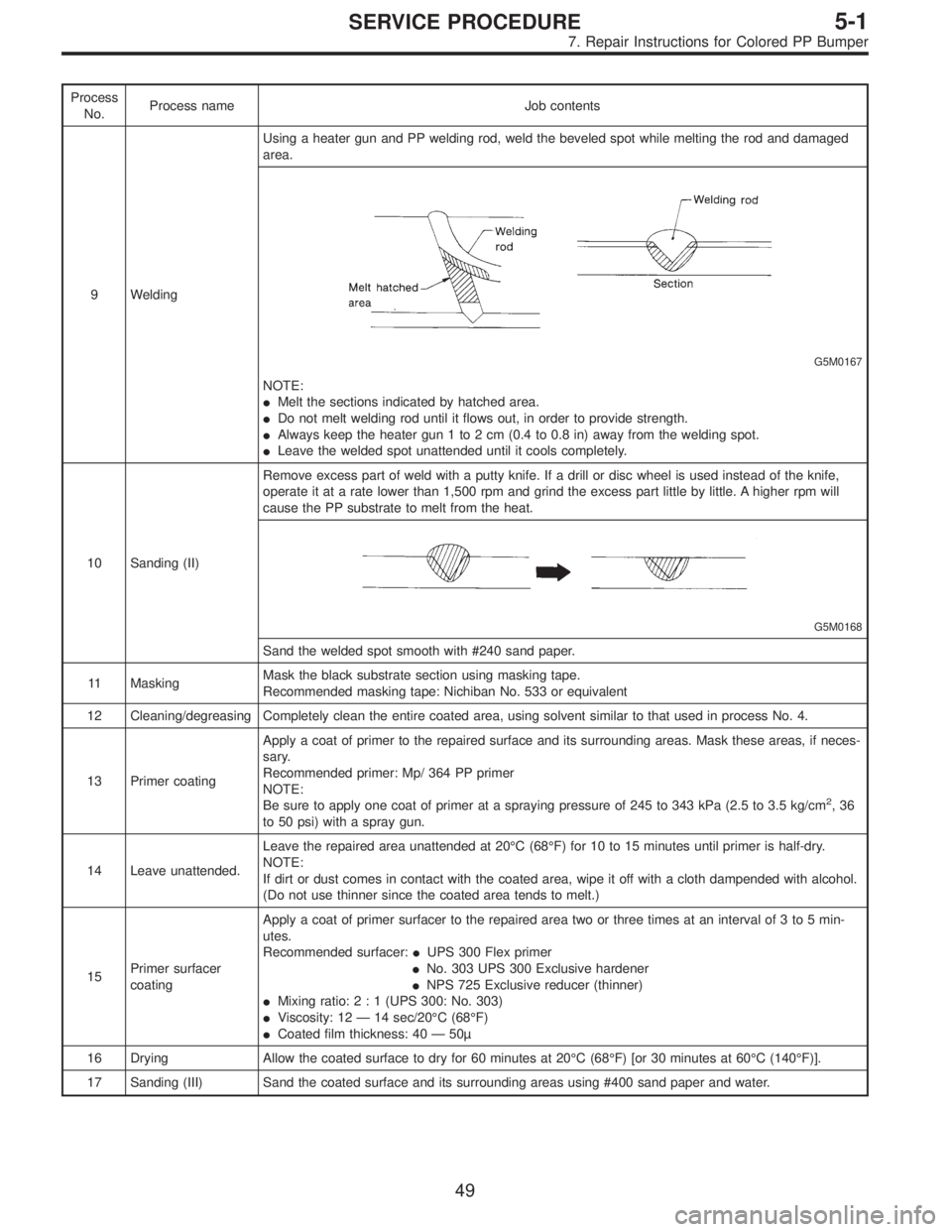
Process
No.Process name Job contents
9 WeldingUsing a heater gun and PP welding rod, weld the beveled spot while melting the rod and damaged
area.
G5M0167
NOTE:
�Melt the sections indicated by hatched area.
�Do not melt welding rod until it flows out, in order to provide strength.
�Always keep the heater gun 1 to 2 cm (0.4 to 0.8 in) away from the welding spot.
�Leave the welded spot unattended until it cools completely.
10 Sanding (II)Remove excess part of weld with a putty knife. If a drill or disc wheel is used instead of the knife,
operate it at a rate lower than 1,500 rpm and grind the excess part little by little. A higher rpm will
cause the PP substrate to melt from the heat.
G5M0168
Sand the welded spot smooth with #240 sand paper.
11 MaskingMask the black substrate section using masking tape.
Recommended masking tape: Nichiban No. 533 or equivalent
12 Cleaning/degreasing Completely clean the entire coated area, using solvent similar to that used in process No. 4.
13 Primer coatingApply a coat of primer to the repaired surface and its surrounding areas. Mask these areas, if neces-
sary.
Recommended primer: Mp/ 364 PP primer
NOTE:
Be sure to apply one coat of primer at a spraying pressure of 245 to 343 kPa (2.5 to 3.5 kg/cm
2,36
to 50 psi) with a spray gun.
14 Leave unattended.Leave the repaired area unattended at 20°C (68°F) for 10 to 15 minutes until primer is half-dry.
NOTE:
If dirt or dust comes in contact with the coated area, wipe it off with a cloth dampended with alcohol.
(Do not use thinner since the coated area tends to melt.)
15Primer surfacer
coatingApply a coat of primer surfacer to the repaired area two or three times at an interval of 3 to 5 min-
utes.
Recommended surfacer:�UPS 300 Flex primer
�No. 303 UPS 300 Exclusive hardener
�NPS 725 Exclusive reducer (thinner)
�Mixing ratio:2:1(UPS 300: No. 303)
�Viscosity: 12—14 sec/20°C (68°F)
�Coated film thickness: 40—50µ
16 Drying Allow the coated surface to dry for 60 minutes at 20°C (68°F) [or 30 minutes at 60°C (140°F)].
17 Sanding (III) Sand the coated surface and its surrounding areas using #400 sand paper and water.
49
5-1SERVICE PROCEDURE
7. Repair Instructions for Colored PP Bumper
Page 1562 of 2890
1) Remove front seats.
2) Remove rear seat cushion.
3) Remove console box.
4) Remove front pillar lower trim panel.
5) Remove center pillar lower trim panel.
6) Remove side sill cover.
7) Remove fuel opener cover.
G5M0368
8) Remove clip under front seat.
9) Remove clip in toe board area.
NOTE:
When pulling out edge, do not pull mat alone; pull mat
together with edge.
Pry off two steel clips on side sill front cover and one on
side sill rear cover using screwdriver.
10) Remove mat hook.
11) Remove mat from toe board area.
12) Remove mat from heater module.
13) Roll mat, and take it out of opened rear door.
14) Installation is in the reverse order of removal.
NOTE:
�Secure mat firmly with hook and velcro tape.
�Insert mat edge firmly into the groove of side sill cover.
16
5-3SERVICE PROCEDURE
5. Inner Trim Panel
Page 1567 of 2890
B5M0026
7) Remove cover back panel.
G5M0278
8) Remove two bolts and lower steering column.
B5M0027
9) Set temperature control lever to Max. COLD position,
and then disconnect temperature control cable from link of
heater module.
NOTE:
Do not move lever and link when installing.
B5M0028
10) Remove bolt cover and bolt of both side.
B5M0029A
11) Remove front side sill cover RH and then disconnect
airbag connector (AB9) and (AB10) (Airbag model).
to 5-5 [M2-6].>
6
5-4SERVICE PROCEDURE
1. Instrument Panel