Page 737 of 2890
11) Install front exhaust pipe and center exhaust pipe.
12) Connect hoses, connectors and cables.
(1) Connect the following hoses.
�Fuel delivery hose, return hose and evaporation
hose
�Heater inlet and outlet hoses
�Brake booster vacuum hose
(2) Connect the following connectors.
�Engine ground terminal
�Engine harness connectors
�Front oxygen sensor connector
�Rear oxygen sensor connector
�Alternator connector and terminal
�A/C compressor connectors (With A/C)
(3) Connect the following cables.
�Accelerator cable
�Cruise control cables (With cruise control)
�Clutch cable
�Clutch release spring
CAUTION:
After connecting each cable, adjust them.
G2M0271
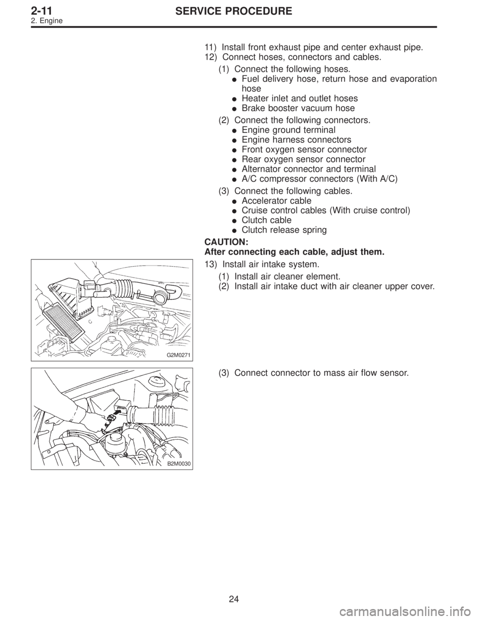
13) Install air intake system.
(1) Install air cleaner element.
(2) Install air intake duct with air cleaner upper cover.
B2M0030
(3) Connect connector to mass air flow sensor.
24
2-11SERVICE PROCEDURE
2. Engine
Page 1282 of 2890
2. CHECKING THE HYDRAULIC UNIT OPERATION BY
PRESSURE GAUGE
1) Remove the FL and FR pipes from the hydraulic unit.
G4M0460
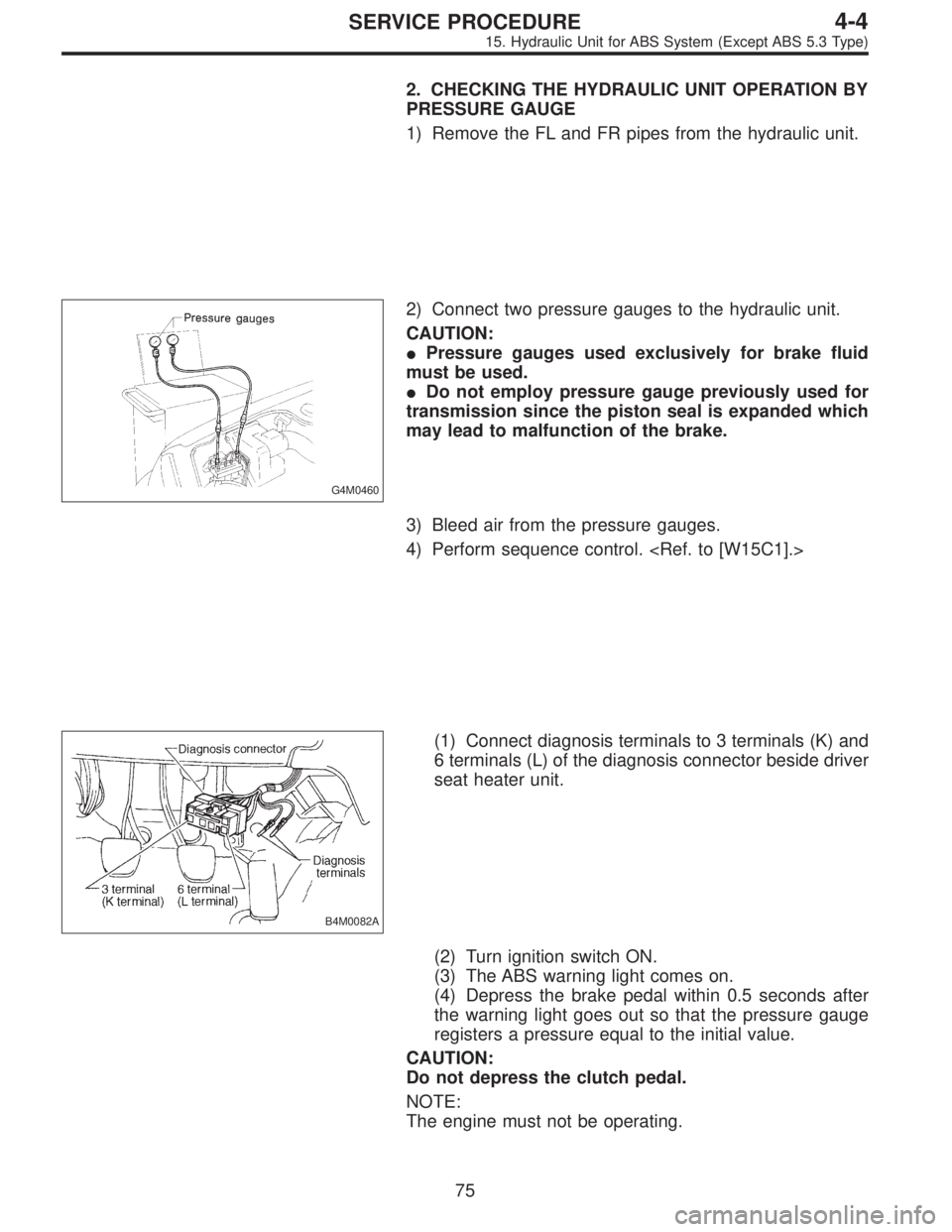
2) Connect two pressure gauges to the hydraulic unit.
CAUTION:
�Pressure gauges used exclusively for brake fluid
must be used.
�Do not employ pressure gauge previously used for
transmission since the piston seal is expanded which
may lead to malfunction of the brake.
3) Bleed air from the pressure gauges.
4) Perform sequence control.
B4M0082A
(1) Connect diagnosis terminals to 3 terminals (K) and
6 terminals (L) of the diagnosis connector beside driver
seat heater unit.
(2) Turn ignition switch ON.
(3) The ABS warning light comes on.
(4) Depress the brake pedal within 0.5 seconds after
the warning light goes out so that the pressure gauge
registers a pressure equal to the initial value.
CAUTION:
Do not depress the clutch pedal.
NOTE:
The engine must not be operating.
75
4-4SERVICE PROCEDURE
15. Hydraulic Unit for ABS System (Except ABS 5.3 Type)
Page 1284 of 2890
 In the case of AWD vehicles, install a spare fuse with
the FWD connector in the engine compartment to simulate
FWD vehicles.
B4M0082A
2) Con")
G4M0462
3. CHECKING THE HYDRAULIC UNIT WITH BRAKE
TESTER
1) In the case of AWD vehicles, install a spare fuse with
the FWD connector in the engine compartment to simulate
FWD vehicles.
B4M0082A
2) Connect diagnosis terminals to 3 terminals (K) and 6
terminals (L) of the diagnosis connector beside driver seat
heater unit.
G4M0464
3) Set the front wheels or rear wheels on the brake tester
and set the select lever’s position at“neutral”.
4) Operate the brake tester.
5) Perform sequence control.
(1) Turn ignition switch ON.
(2) The ABS warning light comes on.
(3) Depress the brake pedal within 0.5 seconds after
the warning light goes out so that the brake tester reg-
isters a pressure equal to the initial value.
CAUTION:
Do not depress the clutch pedal.
NOTE:
The engine must not be operating.
6) Hydraulic unit begins to work; and check the following
working sequence.
(1) The left front wheel performs decompression,
holding, and compression in sequence, and subse-
quently the right front wheel repeats the cycle.
(2) Simultaneously both right and left rear wheel per-
form decompression, holding, and compression in
sequence.
77
4-4SERVICE PROCEDURE
15. Hydraulic Unit for ABS System (Except ABS 5.3 Type)
Page 1285 of 2890
 Read values indicated on the brake tester and check if
the fluctuation of values, when decompressed and
compressed, meet the standard values.
Initial value When decompressed When compressed
Front w")
7) Read values indicated on the brake tester and check if
the fluctuation of values, when decompressed and
compressed, meet the standard values.
Initial value When decompressed When compressed
Front wheel 1,961 N (200 kg, 441 lb) 245 N (25 kg, 55 lb) 1,961 N (200 kg, 441 lb)
Rear wheel 686 N (70 kg, 154 lb) 245 N (25 kg, 55 lb) 686 N (70 kg, 154 lb)
�In case of hydraulic unit plunger piston malfunction:
Initial value When decompressed When compressed
Rear right wheel 686 N (70 kg, 154 lb) 245 N (25 kg, 55 lb) 686 N (70 kg, 154 lb)
Rear left wheel 686 N (70 kg, 154 lb) 686 N (70 kg, 154 lb) 686 N (70 kg, 154 lb)
8) After checking, also check if any irregular brake pedal
tightness is felt.
9) In case of AWD vehicles, remove the spare fuse from
the FWD connector in the engine compartment to return to
the original AWD state.
C: SEQUENCE CONTROL
Under the sequence control, after the hydraulic unit sole-
noid valve is driven, the operation of the hydraulic unit can
be checked by means of the brake tester or pressure
gauge.
B4M0082A
1. OPERATIONAL GUIDELINES OF THE SEQUENCE
CONTROL
1) Connect diagnosis terminals to 3 terminals (K) and 6
terminals (L) of the diagnosis connector beside driver seat
heater unit.
2) Set the speed of all wheels at 4 km/h (2 MPH) or less.
3) Within 0.5 seconds after the ABS warning lamp goes
out, immediately after the ignition switch is turned to on,
depress the brake pedal and hold.
CAUTION:
Do not depress the clutch pedal.
NOTE:
�When the ignition switch is set to on, the brake pedal
must not be depressed.
�Engine must not operate.
78
4-4SERVICE PROCEDURE
15. Hydraulic Unit for ABS System (Except ABS 5.3 Type)
Page 1299 of 2890

3. CONDITIONS FOR COMPLETION OF AIR
BLEEDING CONTROL
When any of the following conditions occurs, ABS and TCS
warning lights illuminate. Air bleeding control stops, while
the ABS and TCS function will then stop. The brake sys-
tem functions as a conventional brake system.
1) When the speed of at least one wheel reaches 10 km/h
(6 MPH).
2) When terminal No. 4 is separated from diagnosis termi-
nal. (When select monitor is not used.)
3) When pump motor remains ON for two minutes.
4) When TCS valve remains open for two minutes.
5) When outlet valve remains closed for two minutes.
6) When malfunction is detected.
NOTE:
When a malfunction is detected the air bleeding operation
stops and the trouble codes are stored in memory.
B4M0082C
C: AIR BLEEDING CONTROL WITH
DIAGNOSIS CONNECTOR
1) Connect diagnosis terminals to terminal No. 4 of the
diagnosis connector beside driver’s seat heater unit.
B4M0621A
2) Start the engine while pushing TCS OFF switch.
NOTE:
Keep the TCS OFF switch depressed even after the engine
has started.
3) After ABS and TCS warning lights go out, depress
brake pedal within 0.5 seconds.
4) After ensuring TCS ON indicator illuminates, release
TCS OFF switch and brake pedal.
5) Air bleeding control operation starts.
90
4-4SERVICE PROCEDURE
19. Air Bleeding (With TCS model)
Page 1306 of 2890
 Under the ABS sequence control, after the hydraulic
unit solenoid valve is driven, the operation of the hydraulic
unit can be checked by means of the brake tester or pres-
s")
D: ABS SEQUENCE CONTROL
1) Under the ABS sequence control, after the hydraulic
unit solenoid valve is driven, the operation of the hydraulic
unit can be checked by means of the brake tester or pres-
sure gauge.
2) ABS sequence control can be started by diagnosis con-
nector or select monitor.
B4M0082C
1. OPERATIONAL GUIDELINES OF THE ABS
SEQUENCE CONTROL WITH DIAGNOSIS
CONNECTOR
1) Connect diagnosis terminals to terminal No. 4 of the
diagnosis connector beside driver’s seat heater unit.
2) Ignition switch is turned to ON.
3) Make sure only the start code (code 11) is shown in
normal condition.
NOTE:
When trouble codes are stored in memory, repair the faulty
parts.
4) Set the speed of all wheels at 10 km/h (6 MPH) or less.
5) Turn ignition switch OFF.
6) Within 0.5 seconds after the ABS and TCS warning
lights go out, depress the brake pedal and hold it immedi-
ately after engine starts.
NOTE:
�When the ignition switch is set to on, the brake pedal
must not be depressed.
�Engine must operate.
�If brake pedal is not depressed within 0.5 seconds after
ABS and TCS warning lights go out, the trouble code mode
comes on.
7) After completion of ABS sequence control, turn ignition
switch OFF.
2. OPERATIONAL GUIDELINES OF THE ABS
SEQUENCE CONTROL WITH SELECT MONITOR
1) Connect select monitor to data link connector beside
driver’s seat heater unit.
2) Engine starts.
3) Put select monitor to TCS mode.
4) put select monitor to FBI mode. Make sure code 11 is
indicated.
NOTE:
When trouble codes are stored in memory, repair the faulty
parts.
97
4-4SERVICE PROCEDURE
20. Hydraulic Unit for ABS/TCS System
Page 1312 of 2890
 Under the TCS sequence control, after the hydraulic
unit solenoid valve is driven, the operation of the hydraulic
unit can be checked by means of the brake tester or pres-
s")
F: TCS SEQUENCE CONTROL
1) Under the TCS sequence control, after the hydraulic
unit solenoid valve is driven, the operation of the hydraulic
unit can be checked by means of the brake tester or pres-
sure gauge.
2) TCS sequence control can be started by diagnosis con-
nector or select monitor.
B4M0082C
1. OPERATIONAL GUIDELINES OF THE TCS
SEQUENCE CONTROL WITH DIAGNOSIS
CONNECTOR
1) Connect diagnosis terminals to terminal No. 4 of the
diagnosis connector beside driver seat heater unit.
2) Ignition switch is turned to ON.
3) Make sure only the start code (code 11) is shown in
normal condition.
NOTE:
When trouble codes are stored in memory, repair the faulty
parts.
4) Set the speed of all wheels at 10 km/h (6 MPH) or less.
5) Turn ignition switch OFF.
6) Start engine, and within 0.5 seconds after the ABS
warning light and TCS warning light go out, press TCS OFF
switch. Within 1.0 second thereafter, release and press the
switch again. Then, keep the switch pressed.
NOTE:
�When the TCS sequence control is set to on, the brake
pedal must not be depressed.
�Engine must operate.
�When TCS OFF switch is not depressed within 0.5 sec-
onds after ABS and TCS warning lights turn off, the trouble
code mode comes on.
7) After completion of TCS sequence control, turn ignition
switch OFF.
103
4-4SERVICE PROCEDURE
20. Hydraulic Unit for ABS/TCS System
Page 1313 of 2890
2. OPERATIONAL GUIDELINES OF THE TCS
SEQUENCE CONTROL WITH SELECT MONITOR
1) Connect select monitor to data link connector beside
driver’s seat heater unit.
2) Engine starts.
3) Put select monitor to TCS mode.
4) Put select monitor to FBI mode. Make sure code 11 is
indicated.
NOTE:
When trouble codes are stored in memory, repair the faulty
parts.
B4M0639
5) Press FD2 ENT key.
B4M0624
6) When the message shown in the figure is displayed,
press ENT key.
7) Checked portions will be displayed on select monitor.
B4M0627
8) When TCS sequence control cannot be started (by sys-
tem malfunction, etc.), the message shown in the figure will
be displayed.
NOTE:
Read the trouble codes. Repair faulty parts.
104
4-4SERVICE PROCEDURE
20. Hydraulic Unit for ABS/TCS System
![SUBARU LEGACY 1996 Service Repair Manual 2. OPERATIONAL GUIDELINES OF THE TCS
SEQUENCE CONTROL WITH SELECT MONITOR
1) Connect select monitor to data link connector beside
driver’s seat heater unit. <Ref. to [W19D0] step 1).>
2) Engine star](/manual-img/17/57433/w960_57433-1312.png "SUBARU LEGACY 1996 Service Repair Manual 2. OPERATIONAL GUIDELINES OF THE TCS
SEQUENCE CONTROL WITH SELECT MONITOR
1) Connect select monitor to data link connector beside
driver’s seat heater unit. <Ref. to [W19D0] step 1).>
2) Engine star")