Page 1630 of 2890
G2M0090
5) Remove bolts which install generator onto bracket.
G2M0090
6) Installation is in the reverse order of removal.
CAUTION:
Check and adjust V-belt tension.
B6M0476A
B: DISASSEMBLY
1) Heat the portion�Aof rear cover to 50°C (122°F) with
heater drier.
G6M0065
2) Remove the four through bolts. Then insert the tip of a
flat-head screwdriver into the gap between the stator core
and front bracket. Pry then apart to disassemble.
G6M0066
3) Hold rotor with a vise and remove pulley nut.
16
6-1SERVICE PROCEDURE
2. Generator
Page 1635 of 2890
2) Check operation as shown in chart below.
No.Switch operation
Value of
voltage meterLamp operation
Remarks
123 12
1 ON OFF OFF 12 V DIM ONCheck initial
excitation.
2 ON ON OFF 12 VON
or
BLINKOFF Check total excitation.
3 ON ON OFF 16 VOFF
or
DIM-BLINKOFFWhen value of voltage
meter is between 12
V and 16 V.
4 OFF ON OFF 12 VON
or
BLINKONCheck connection for
S and B terminals.
5 OFF ON ON 18 V ON ONCheck for over
loading of voltage.
G6M0077
D: ASSEMBLY
Assembly is in the reverse order of disassembly proce-
dures.
CAUTION:
�When disassembling generator, replace rear ball
bearing.
�When soldering starter coil to diode, do not touch
lead wire with solder for more than 5 seconds.
B6M0492
�Before installing rear cover, insert pin from outside
of rear cover so that holds brush. After installing rear
cover, remove pin.
B6M0476A
�When installing rear cover, heat portion�Ato 50°C
(122°F) with heater drier.
21
6-1SERVICE PROCEDURE
2. Generator
Page 1726 of 2890
23. Seat Heater
A: REMOVAL AND INSTALLATION
1. SEAT HEATER
Refer to 5-3 [W1A0] as for removal of seat (including
heater system).
B6M0150A
2. SEAT HEATER SWITCH
1) Remove screws which secure rear console cover, and
then remove rear console cover.
2) Remove seat heater switch from console cover.
B6M0151A
B: INSPECTION
1. SEAT HEATER
Check continuity between terminals of seat heater connec-
tor.
�Between terminals No. 1 and No. 3
�Between terminals No. 1 and No. 4
�Between terminals No. 3 and No. 4
B6M0152
2. SEAT HEATER SWITCH
Set switch to each position and check continuity between
terminals as indicated in table below:
Terminal
Switch562 34 1
OFF�
���
LO������
HI
��
��
�
���
62
6-2SERVICE PROCEDURE
23. Seat Heater
Page 1805 of 2890

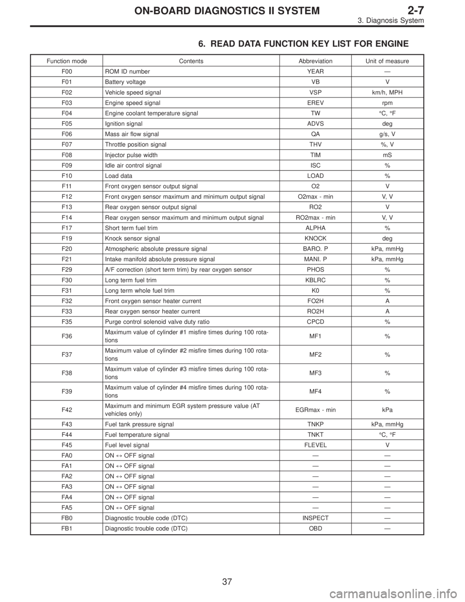
6. READ DATA FUNCTION KEY LIST FOR ENGINE
Function mode Contents Abbreviation Unit of measure
F00 ROM ID number YEAR—
F01 Battery voltage VB V
F02 Vehicle speed signal VSP km/h, MPH
F03 Engine speed signal EREV rpm
F04 Engine coolant temperature signal TW°C,°F
F05 Ignition signal ADVS deg
F06 Mass air flow signal QA g/s, V
F07 Throttle position signal THV %, V
F08 Injector pulse width TIM mS
F09 Idle air control signal ISC %
F10 Load data LOAD %
F11 Front oxygen sensor output signal O2 V
F12 Front oxygen sensor maximum and minimum output signal O2max - min V, V
F13 Rear oxygen sensor output signal RO2 V
F14 Rear oxygen sensor maximum and minimum output signal RO2max - min V, V
F17 Short term fuel trim ALPHA %
F19 Knock sensor signal KNOCK deg
F20 Atmospheric absolute pressure signal BARO. P kPa, mmHg
F21 Intake manifold absolute pressure signal MANI. P kPa, mmHg
F29 A/F correction (short term trim) by rear oxygen sensor PHOS %
F30 Long term fuel trim KBLRC %
F31 Long term whole fuel trim K0 %
F32 Front oxygen sensor heater current FO2H A
F33 Rear oxygen sensor heater current RO2H A
F35 Purge control solenoid valve duty ratio CPCD %
F36Maximum value of cylinder #1 misfire times during 100 rota-
tionsMF1 %
F37Maximum value of cylinder #2 misfire times during 100 rota-
tionsMF2 %
F38Maximum value of cylinder #3 misfire times during 100 rota-
tionsMF3 %
F39Maximum value of cylinder #4 misfire times during 100 rota-
tionsMF4 %
F42Maximum and minimum EGR system pressure value (AT
vehicles only)EGRmax - min kPa
F43 Fuel tank pressure signal TNKP kPa, mmHg
F44 Fuel temperature signal TNKT°C,°F
F45 Fuel level signal FLEVEL V
FA 0 O N)OFF signal——
FA 1 O N)OFF signal——
FA 2 O N)OFF signal——
FA 3 O N)OFF signal——
FA 4 O N)OFF signal——
FA 5 O N)OFF signal——
FB0 Diagnostic trouble code (DTC) INSPECT—
FB1 Diagnostic trouble code (DTC) OBD—
37
2-7ON-BOARD DIAGNOSTICS II SYSTEM
3. Diagnosis System
Page 1812 of 2890
B2M0497
29. FUNCTION MODE: F32
—FRONT OXYGEN SENSOR HEATER CURRENT
(FO2H)—
B2M0498
30. FUNCTION MODE: F33
—REAR OXYGEN SENSOR HEATER CURRENT
(RO2H)—
H2M1325
31. FUNCTION MODE: F35
—PURGE CONTROL SOLENOID VALVE DUTY RATIO
(CPCD)—
B2M0499
32. FUNCTION MODE: F36
—MAXIMUM VALUE OF CYLINDER #1 MISFIRE RATE
DURING 100 ROTATIONS (MF1)—
B2M0500
33. FUNCTION MODE: F37
—MAXIMUM VALUE OF CYLINDER #2 MISFIRE RATE
DURING 100 ROTATIONS (MF2)—
44
2-7ON-BOARD DIAGNOSTICS II SYSTEM
3. Diagnosis System
Page 1839 of 2890

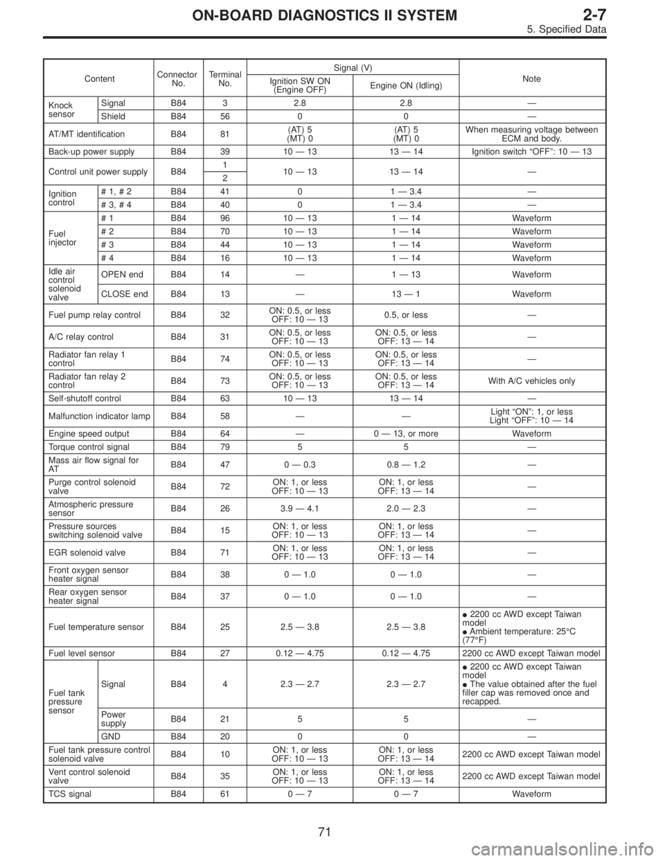
ContentConnector
No.Terminal
No.Signal (V)
Note
Ignition SW ON
(Engine OFF)Engine ON (Idling)
Knock
sensorSignal B84 3 2.8 2.8—
Shield B84 56 0 0—
AT/MT identification B84 81(AT) 5
(MT) 0(AT) 5
(MT) 0When measuring voltage between
ECM and body.
Back-up power supply B84 39 10—13 13—14 Ignition switch“OFF”:10—13
Control unit power supply B841
10—13 13—14—
2
Ignition
control#1,#2 B84 41 0 1—3.4—
#3,#4 B84 40 0 1—3.4—
Fuel
injector# 1 B84 96 10—13 1—14 Waveform
# 2 B84 70 10—13 1—14 Waveform
# 3 B84 44 10—13 1—14 Waveform
# 4 B84 16 10—13 1—14 Waveform
Idle air
control
solenoid
valveOPEN end B84 14—1—13 Waveform
CLOSE end B84 13—13—1 Waveform
Fuel pump relay control B84 32ON: 0.5, or less
OFF: 10—130.5, or less—
A/C relay control B84 31ON: 0.5, or less
OFF: 10—13ON: 0.5, or less
OFF: 13—14—
Radiator fan relay 1
controlB84 74ON: 0.5, or less
OFF: 10—13ON: 0.5, or less
OFF: 13—14—
Radiator fan relay 2
controlB84 73ON: 0.5, or less
OFF: 10—13ON: 0.5, or less
OFF: 13—14With A/C vehicles only
Self-shutoff control B84 63 10—13 13—14—
Malfunction indicator lamp B84 58——Light“ON”:1,orless
Light“OFF”:10—14
Engine speed output B84 64—0—13, or more Waveform
Torque control signal B84 79 5 5—
Mass air flow signal for
ATB84 47 0—0.3 0.8—1.2—
Purge control solenoid
valveB84 72ON: 1, or less
OFF: 10—13ON: 1, or less
OFF: 13—14—
Atmospheric pressure
sensorB84 26 3.9—4.1 2.0—2.3—
Pressure sources
switching solenoid valveB84 15ON: 1, or less
OFF: 10—13ON: 1, or less
OFF: 13—14—
EGR solenoid valve B84 71ON: 1, or less
OFF: 10—13ON: 1, or less
OFF: 13—14—
Front oxygen sensor
heater signalB84 38 0—1.0 0—1.0—
Rear oxygen sensor
heater signalB84 37 0—1.0 0—1.0—
Fuel temperature sensor B84 25 2.5—3.8 2.5—3.8�2200 cc AWD except Taiwan
model
�Ambient temperature: 25°C
(77°F)
Fuel level sensor B84 27 0.12—4.75 0.12—4.75 2200 cc AWD except Taiwan model
Fuel tank
pressure
sensorSignal B84 4 2.3—2.7 2.3—2.7�2200 cc AWD except Taiwan
model
�The value obtained after the fuel
filler cap was removed once and
recapped.
Power
supplyB84 21 5 5—
GND B84 20 0 0—
Fuel tank pressure control
solenoid valveB84 10ON: 1, or less
OFF: 10—13ON: 1, or less
OFF: 13—142200 cc AWD except Taiwan model
Vent control solenoid
valveB84 35ON: 1, or less
OFF: 10—13ON: 1, or less
OFF: 13—142200 cc AWD except Taiwan model
TCS signal B84 61 0—70—7 Waveform
71
2-7ON-BOARD DIAGNOSTICS II SYSTEM
5. Specified Data
Page 1840 of 2890
ContentConnector
No.Terminal
No.Signal (V)
Note
Ignition SW ON
(Engine OFF)Engine ON (Idling)
AT diagnosis input signal B84 80Less than 1)More
than 4Less than 1)More
than 4Waveform
GND (sensors) B84 20 0 0—
GND (injectors) B8469
00—
95
GND (ignition system) B84 94 0 0—
GND (power supply) B8419
00—
46
GND (control systems) B8417
00—
18
GND (oxygen sensor
heater)B84 42 0 0—
2. ENGINE CONDITION DATA
Content Model Specified data
Mass air flow2200 cc1.7—3.3 (g/sec): Idling
7.1—14.2 (g/sec): 2,500 rpm racing
2500 cc2.2—4.2 (g/sec): Idling
8.6—14.5 (g/sec): 2,500 rpm racing
Engine load2200 cc1.6—2.9 (%): Idling
6.4—12.8 (%): 2,500 rpm racing
2500 cc1.9—3.5 (%): Idling
7.2—12.1 (%): 2,500 rpm racing
Measuring condition:
�After warm-up the engine.
�Gear position is in“N”or“P”position.
�A/C is turned OFF.
�All accessory switches are turned OFF.
72
2-7ON-BOARD DIAGNOSTICS II SYSTEM
5. Specified Data
Page 1891 of 2890

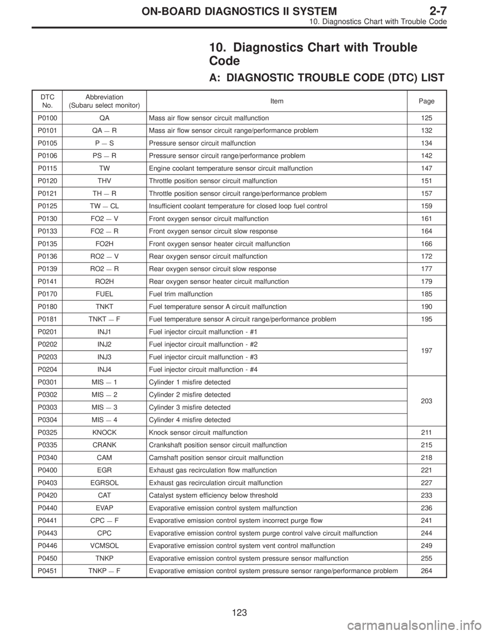
10. Diagnostics Chart with Trouble
Code
A: DIAGNOSTIC TROUBLE CODE (DTC) LIST
DTC
No.Abbreviation
(Subaru select monitor)Item Page
P0100 QA Mass air flow sensor circuit malfunction 125
P0101 QA
—R Mass air flow sensor circuit range/performance problem 132
P0105 P
—S Pressure sensor circuit malfunction 134
P0106 PS
—R Pressure sensor circuit range/performance problem 142
P0115 TW Engine coolant temperature sensor circuit malfunction 147
P0120 THV Throttle position sensor circuit malfunction 151
P0121 TH
—R Throttle position sensor circuit range/performance problem 157
P0125 TW
—CL Insufficient coolant temperature for closed loop fuel control 159
P0130 FO2
—V Front oxygen sensor circuit malfunction 161
P0133 FO2
—R Front oxygen sensor circuit slow response 164
P0135 FO2H Front oxygen sensor heater circuit malfunction 166
P0136 RO2
—V Rear oxygen sensor circuit malfunction 172
P0139 RO2
—R Rear oxygen sensor circuit slow response 177
P0141 RO2H Rear oxygen sensor heater circuit malfunction 179
P0170 FUEL Fuel trim malfunction 185
P0180 TNKT Fuel temperature sensor A circuit malfunction 190
P0181 TNKT
—F Fuel temperature sensor A circuit range/performance problem 195
P0201 INJ1 Fuel injector circuit malfunction - #1
197 P0202 INJ2 Fuel injector circuit malfunction - #2
P0203 INJ3 Fuel injector circuit malfunction - #3
P0204 INJ4 Fuel injector circuit malfunction - #4
P0301 MIS
—1 Cylinder 1 misfire detected
203 P0302 MIS
—2 Cylinder 2 misfire detected
P0303 MIS
—3 Cylinder 3 misfire detected
P0304 MIS
—4 Cylinder 4 misfire detected
P0325 KNOCK Knock sensor circuit malfunction 211
P0335 CRANK Crankshaft position sensor circuit malfunction 215
P0340 CAM Camshaft position sensor circuit malfunction 218
P0400 EGR Exhaust gas recirculation flow malfunction 221
P0403 EGRSOL Exhaust gas recirculation circuit malfunction 227
P0420 CAT Catalyst system efficiency below threshold 233
P0440 EVAP Evaporative emission control system malfunction 236
P0441 CPC
—F Evaporative emission control system incorrect purge flow 241
P0443 CPC Evaporative emission control system purge control valve circuit malfunction 244
P0446 VCMSOL Evaporative emission control system vent control malfunction 249
P0450 TNKP Evaporative emission control system pressure sensor malfunction 255
P0451 TNKP
—F Evaporative emission control system pressure sensor range/performance problem 264
123
2-7ON-BOARD DIAGNOSTICS II SYSTEM
10. Diagnostics Chart with Trouble Code