Page 1852 of 2890
.
1) Turn ignition switch to OFF.
2) Disconnect test mode connector.
3) Turn ignition switch to ON.
: Does the MIL come on?")
B2M0470C
7C1CHECK OPERATION OF CHECK ENGINE
MALFUNCTION INDICATOR LAMP (MIL).
1) Turn ignition switch to OFF.
2) Disconnect test mode connector.
3) Turn ignition switch to ON.
: Does the MIL come on?
: Go to step7C2.
: Repair the MIL circuit.
B2M0512A
7C2
CHECK OUTPUT SIGNAL FROM ECM.
Measure voltage between test mode connector and chas-
sis ground.
: Connector & terminal
(B75) No.1 (+)—Chassis ground (�):
Is voltage less than 1 V?
: Go to step7C3.
: Go to step7C4.
B2M0513A
7C3CHECK HARNESS BETWEEN ECM AND
TEST MODE CONNECTOR.
1) Turn ignition switch to OFF.
2) Disconnect connector from ECM.
3) Measure resistance of harness between ECM and test
mode connector.
: Connector & terminal
(B84) No.84—(B75) No.1:
Is resistance less than 1Ω?
: Go to next.
: Repair open circuit in harness between ECM and
test mode connector.
: Is there poor contact in ECM connector?
: Repair poor contact in ECM connector.
: Replace ECM.
84
2-7ON-BOARD DIAGNOSTICS II SYSTEM
7. Diagnostics for CHECK ENGINE Malfunction Indicator Lamp (MIL)
Page 1859 of 2890
 Turn ignition switch to OFF.
2) Disconnect connector from starter motor.
3) Turn ignition switch to ST.
OBD0100A
4) Measure power supply voltage bet")
OBD0724
8B1CHECK INPUT SIGNAL FOR STARTER
MOTOR.
1) Turn ignition switch to OFF.
2) Disconnect connector from starter motor.
3) Turn ignition switch to ST.
OBD0100A
4) Measure power supply voltage between starter motor
connector terminal and engine ground.
: Connector & terminal
(B14) No. 1 (+)—Engine ground (�):
Is the voltage more than 10 V?
NOTE:
�On AT vehicles, place the selector lever in the“P”or“N”
position.
�On MT vehicles, depress the clutch pedal.
: Go to step8B2.
: Go to step8B3.
OBD0725
8B2CHECK GROUND CIRCUIT OF STARTER
MOTOR.
1) Turn ignition switch to OFF.
2) Disconnect terminal from starter motor.
3) Measure resistance of ground cable between ground
cable terminal and engine ground.
: Is resistance less than 5Ω?
: Check starter motor.
: Repair open circuit of ground cable.
8B3CHECK HARNESS BETWEEN BATTERY
AND IGNITION SWITCH CONNECTOR.
1) Turn ignition switch to OFF.
2) Remove SBF No. 4 from main fuse box.
3) Measure resistance of fuse.
: Is resistance less than 1Ω?
: Replace SBF No. 4.
: Go to next step 4).
91
2-7ON-BOARD DIAGNOSTICS II SYSTEM
8. Diagnostics for Engine Starting Failure
Page 1870 of 2890
?
: Repair poor contact in coupling connector.
: Repair harness between ignition coil and ignitor
connector.
OBD0728
B2M0224A
8D5
CHECK INPUT SIGNAL")
: Is there poor contact in coupling connector
(B22)?
: Repair poor contact in coupling connector.
: Repair harness between ignition coil and ignitor
connector.
OBD0728
B2M0224A
8D5
CHECK INPUT SIGNAL FOR IGNITOR.
Check if voltage varies synchronously with engine speed
when cranking, while monitoring voltage between ignitor
connector and engine ground.
: Connector & terminal:
(B13) No. 1 (+)—Engine ground (�):
Is the voltage more than 10 V?
: Go to next.
: Replace ignitor.
: Connector & terminal:
(B13) No. 2 (+)—Engine ground (�):
Is the voltage more than 10 V?
: Go to step8D6.
: Replace ignitor.
OBD0128A
8D6CHECK HARNESS OF IGNITOR GROUND
CIRCUIT.
1) Turn ignition switch to OFF.
2) Measure resistance between ignitor and engine ground.
: Connector & terminal
(B13) No. 3—Engine ground:
Is the resistance less than 5Ω?
: Go to step8D7.
: Repair harness between ignitor connector and
engine grounding terminal.
102
2-7ON-BOARD DIAGNOSTICS II SYSTEM
8. Diagnostics for Engine Starting Failure
Page 1886 of 2890

Throttle position sensor
Crankshaft position sensor & Camshaft po")
9. General Diagnostics Table
1. FOR ENGINE
12345678910111213
Problem parts
Mass air flow sensor
Engine coolant temperature sensor (*1)
Throttle position sensor
Crankshaft position sensor & Camshaft position sensor (*2)
Idle air control solenoid valve
Knock sensor
Purge control solenoid valve
EGR valve
Fuel injection parts (*3)
Ignition parts (*4)
Fuel pump and relay
A/C switch and A/C cut relay
Engine torque control signal circuitSymptom
1 Engine stalls during idling.�� � � ���
2 Rough idling�� � � � �
3 Engine does not return to idle.���
4 Poor acceleration�� � � ���
5Engine stalls or engine sags or hesi-
tates at acceleration.�� � � ��� �
6 Surge�� � �� �
7 Spark knock����
8 After burning in exhaust system�� � �
*1: The mark,�, indicates the symptom occurring only in cold temperatures.
*2: For items with the mark,�, ensure the secure installation of crankshaft position sensor and camshaft position sensor. Replacement is
not necessary.
*3: Check fuel injector, fuel pressure regulator and fuel filter.
*4: Check ignitor, ignition coil and spark plug.
NOTE:
Malfunction of parts other than the above is also possible. Refer to 1. Engine Trouble in General [K100] in Repair Section 2-3 or 2-3b of
the Service Manual.
11 8
2-7ON-BOARD DIAGNOSTICS II SYSTEM
9. General Diagnostics Table
Page 1890 of 2890

One-way clutch (3-")
Overrunning clutch
Drive pinion
Crown gear
Axle shaft
Differential gear
Final gear
Seal pipe
Oil pump
High clutch
Band brake
Low & reverse clutch
Reverse clutch
One-way clutch (1-2)
One-way clutch (3-4)
Double oil seal
Input shaft
Output shaft
Planetary gear
Reduction gear
Drive plate
Torque converter one-way clutch
Lock-up facing
Lock-up damper
ATF deterioration
ATF level too high or too low
Differential gear oil level too high or too low
Engine performance
Engine speed signal
Parking brake mechanism
Problem parts
30 31 32 33 34 35 36 37 38 39 40 41 42 43 44 45 46 47 48 49 50 51 52 53 54 55 56 57 58 Symptom
�Engine brake is not effected when select
lever is in“3”or“2”range.
�Engine brake is not effected when select
lever is in“1”range.
Shift characteristics are erroneous.
��No lock-up occurs.
Vehicle cannot be set in“D”range power
mode.
“D”range power mode cannot be released.
�Parking brake is not effected.
�Shift lever cannot be moved or is hard to
move from“P”range.
Select lever is hard to move.
Select lever is too light to move (unreason-
able resistance).
�ATF spurts out.
�Differential oil spurts out.
��Differential oil level changes excessively.
� ���� � �Odor is produced from oil supply pipe.
���Shock occurs when select lever is moved
from“1”to“2”range.
�Slippage occurs when select lever is moved
from“1”to“2”range.
�� � �Shock occurs when select lever is moved
from“2”to“3”range.
��Slippage occurs when select lever is moved
from“2”to“3”range.
�� ��Shock occurs when select lever is moved
from“3”to“4”range.
�Slippage occurs when select lever is moved
from“3”to“4”range.
�� �Shock occurs when select lever is moved
from“3”to“2”range.
�Shock occurs when select lever is moved
from“D”to“1”range.
��Shock occurs when select lever is moved
from“2”to“1”range.
��Shock occurs when accelerator pedal is
released at medium speeds.
��Vibration occurs during straight-forward
operation.
Select lever slips out of position during
acceleration or while driving on rough terrain.
�Vibration occurs during turns (tight corner
“braking”phenomenon).
Front wheel slippage occurs during standing
starts.
Vehicle is not set in FWD mode.
30 31 32 33 34 35 36 37 38 39 40 41 42 43 44 45 46 47 48 49 50 51 52 53 54 55 56 57 58
122
2-7ON-BOARD DIAGNOSTICS II SYSTEM
9. General Diagnostics Table
Page 1897 of 2890

Measure voltage between ECM connector and chassis
ground while engine is idling.
: Connector & terminal
(B84)")
B2M0532A
10B2CHECK INPUT SIGNAL FOR ECM.
(USING VOLTAGE METER AND SUBARU
SELECT MONITOR.)
Measure voltage between ECM connector and chassis
ground while engine is idling.
: Connector & terminal
(B84) No. 5 (+)—Chassis ground (�):
Is the voltage less than 0.3 V?
: Go to step10B3.
: Go to next.
B2M0481
: Does the voltage change more than 0.3 V by
shaking harness and connector of ECM
while monitoring the value with Subaru
select monitor?
: Repair poor contact in ECM connector.
: Replace ECM.
B2M0645A
10B3CHECK POWER SUPPLY TO MASS AIR
FLOW SENSOR.
1) Turn ignition switch to OFF.
2) Disconnect connector from mass air flow sensor.
3) Turn ignition switch to ON.
4) Measure voltage between mass air flow sensor connec-
tor and engine ground.
: Connector & terminal
(B3) No. 1 (+)—Engine ground (�):
Is the voltage more than 10 V?
: Go to step10B4.
: Repair open circuit in harness between main relay
and mass air flow sensor connector.
129
2-7ON-BOARD DIAGNOSTICS II SYSTEM
10. Diagnostics Chart with Trouble Code
Page 1905 of 2890
 Turn ignition switch to OFF.
2) Connect Subaru Select Monitor or the OBD-II general
scan tool to data link")
OBD0145A
10D1CONNECT SUBARU SELECT MONITOR
OR THE OBD-II GENERAL SCAN TOOL,
AND READ DATA.
1) Turn ignition switch to OFF.
2) Connect Subaru Select Monitor or the OBD-II general
scan tool to data link connector.
3) Turn ignition switch to ON and Subaru Select Monitor or
the OBD-II general scan tool switch to ON.
4) Start engine.
B2M0756
5) Read the data on Subaru Select Monitor or the OBD-II
general scan tool.
�Subaru Select Monitor
Designate mode using function key.
Function mode: F21
�F21: Display shows pressure signal value sent from
pressure sensor.
: Is the value less than 0 kPa in function
mode F21?
: Go to step10D2.
: Go to next.
B2M0756
: Is the value more than 140 kPa in function
mode F21?
: Go to step10D4.
: Repair harness and connector.
NOTE:
In this case, repair the following:
�Open or short circuit in harness between pressure sen-
sor and ECM connector
�Poor contact in pressure sensor
�Poor contact in ECM connector
�OBD-II general scan tool
For detailed operation procedures, refer to the OBD-II Gen-
eral Scan Tool Instruction Manual.
137
2-7ON-BOARD DIAGNOSTICS II SYSTEM
10. Diagnostics Chart with Trouble Code
Page 1907 of 2890
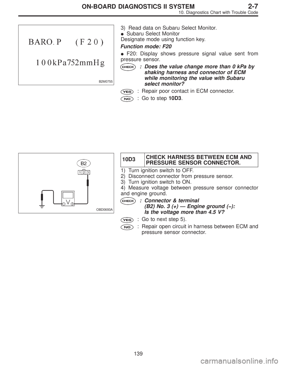
B2M0755
3) Read data on Subaru Select Monitor.
�Subaru Select Monitor
Designate mode using function key.
Function mode: F20
�F20: Display shows pressure signal value sent from
pressure sensor.
: Does the value change more than 0 kPa by
shaking harness and connector of ECM
while monitoring the value with Subaru
select monitor?
: Repair poor contact in ECM connector.
: Go to step10D3.
OBD0693A
10D3CHECK HARNESS BETWEEN ECM AND
PRESSURE SENSOR CONNECTOR.
1) Turn ignition switch to OFF.
2) Disconnect connector from pressure sensor.
3) Turn ignition switch to ON.
4) Measure voltage between pressure sensor connector
and engine ground.
: Connector & terminal
(B2) No. 3 (+)—Engine ground (�):
Is the voltage more than 4.5 V?
: Go to next step 5).
: Repair open circuit in harness between ECM and
pressure sensor connector.
139
2-7ON-BOARD DIAGNOSTICS II SYSTEM
10. Diagnostics Chart with Trouble Code