Page 1814 of 2890
—
40. FA MODE FOR ENGINE
Function
modeLED No. Contents Display LED“ON”requirements
FA 03 Neutral switch NT When neutral position signa")
H2M1327
39. FUNCTION MODE: F45
—FUEL LEVEL SIGNAL (FLEVEL)—
40. FA MODE FOR ENGINE
Function
modeLED No. Contents Display LED“ON”requirements
FA 03 Neutral switch NT When neutral position signal is entered.
7 Test mode connector UD When test mode connector is connected.
8 AT/MT identification signal AT When AT identification signal is entered.
9 Ignition switch IG When ignition switch is turned ON.
FA 11 Radiator fan relay 2 R2 When radiator fan relay 2 is in function.
2 Knock signal KS When knock signal is entered.
3 Purge control solenoid valve CN When purge control solenoid valve is in function.
4 Fuel pump relay FP When fuel pump relay is in function.
6 Radiator fan relay 1 R1 When radiator fan relay 1 is in function.
7 Air conditioner relay AR When air conditioner relay is in function.
8 Air conditioner switch AC When air conditioner switch is turned ON.
FA 22 AEC signal EC When AEC signal is entered.
3 EAM signal AM When EAM signal is gone out.
4 AEB signal EB When AEB signal is entered.
6 AET signal ET When AET signal is entered.
7 Engine torque control signal TR When engine torque control signal is entered.
FA3 7 Pressure sources switching solenoid valve BRWhen pressure sources switching solenoid valve
is in function.
FA 41 Catalyst CA When diagnosis of catalyzer is finished.
2 EGR system E1 When diagnosis of EGR system is finished.
3 California model identification signal FCWhen California model identification signal is
entered.
8 Rear oxygen sensor signal OR When rear oxygen sensor mixture ratio is rich.
9 Front oxygen sensor signal O2 When front oxygen sensor mixture ratio is rich.
FA 56 Vent control solenoid valve AL When vent control solenoid valve is in function.
7 EGR solenoid valve ER When EGR solenoid valve is in function.
8 Pressure control solenoid valve PCWhen pressure control solenoid valve is in
function.
46
2-7ON-BOARD DIAGNOSTICS II SYSTEM
3. Diagnosis System
Page 1815 of 2890

LED No. Signal name Display
1——
2——
3 Neutral switch NT
4——
5——
6——
7 Test mode connector UD
8 Identification of AT model AT
9 Ignition switch IG
0——
——NT——
—UD AT IG—
1
2345
67890
41. FUNCTION MODE: FA0
—ON↔OFF SIGNAL—
Requirement for LED“ON”.
LED No. 3�On MT model, gear position is in neutral.
�On AT model, shift position is in“P”or“N”.
LED No. 7 Test mode connector is connected.
LED No. 8 Vehicle is AT model.
LED No. 9 Ignition switch is turned ON.
LED No. Signal name Display
1 Radiator fan relay 2 R2
2 Knock signal KS
3Purge control solenoid
valveCN
4 Fuel pump relay FP
5——
6 Radiator fan relay 1 R1
7 A/C relay AR
8 A/C switch AC
9——
0——
R2 KS CN FP—
R1 AR AC——
1
2345
67890
42. FUNCTION MODE: FA1
—ON↔OFF SIGNAL—
Requirement for LED“ON”.
LED No. 1 Radiator fan relay 2 is turned ON.
LED No. 2 Engine is knocking.
LED No. 3 Purge control solenoid valve is in function.
LED No. 4 Fuel pump relay is turned ON.
LED No. 6 Radiator fan relay 1 is turned ON.
LED No. 7 A/C relay is turned ON.
LED No. 8 A/C switch is turned ON.
NOTE:
�When LED No. 1, 3, 4, 6 and 7 blinks with the test mode
connector connected and the ignition switch turned to ON,
the corresponding part is functioning properly.
�When LED No. 4 illuminates for only 2 seconds after the
ignition switch is turned to ON, (and then goes out), the
corresponding part is functioning properly.
47
2-7ON-BOARD DIAGNOSTICS II SYSTEM
3. Diagnosis System
Page 1816 of 2890

LED No. Signal name Display
1——
2 AEC signal EC
3 EAM signal AM
4 AEB signal EB
5——
6 AET signal ET
7Engine torque control
signalTR
8——
9——
0——
—EC AM EB—
ET TR———
1
2345
67890
43. FUNCTION MODE: FA2
—ON↔OFF SIGNAL—
Requirement for LED“ON”.
LED No. 2 ECM entered the AEC signal emitted from
TCS C/M.
LED No. 3 EAM signal goes out.
LED No. 4 ECM entered the AEB signal emitted from
TCS C/M.
LED No. 6 ECM entered the AET signal emitted from
TCS C/M.
LED No. 7 ECM entered the torque control signal emit-
ted from TCM.
LED No. Signal name Display
1——
2——
3——
4——
5——
6——
7Pressure sources switching
solenoid valveBR
8——
9——
0——
—————
—BR———
1
2345
67890
44. FUNCTION MODE: FA3
—ON↔OFF SIGNAL—
Requirement for LED“ON”.
LED No. 7 Pressure sources switching solenoid valve is
in function.
NOTE:
When LED No. 7 blinks with the test mode connector con-
nected and the ignition switch turned to ON, the corre-
sponding part is functioning properly.
48
2-7ON-BOARD DIAGNOSTICS II SYSTEM
3. Diagnosis System
Page 1817 of 2890

LED No. Signal name Display
1 Catalyst CA
2 EGR system E1
3California model
identification signalFC
4——
5——
6——
7——
8 Rear oxygen sensor signal OR
9 Front oxygen sensor signal O2
0——
CA E1 FC——
——OR O2—
1
2345
67890
45. FUNCTION MODE: FA4
—ON↔OFF SIGNAL—
Requirement for LED“ON”.
LED No. 1 Diagnosis of catalyzer is finished.
LED No. 2 Diagnosis of EGR system is finished.
LED No. 3 Vehicle is except California model.
LED No. 8 Rear oxygen sensor mixture ratio is rich.
LED No. 9 Front oxygen sensor mixture ratio is rich.
LED No. Signal name Display
1——
2——
3——
4——
5——
6 Vent control solenoid valve AL
7 EGR solenoid valve ER
8Pressure control solenoid
valvePC
9——
0——
—————
AL ER PC——
1
2345
67890
46. FUNCTION MODE: FA5
—ON↔OFF SIGNAL—
Requirement for LED“ON”.
LED No. 6 Vent control solenoid valve is in function.
LED No. 7 EGR solenoid valve is in function.
LED No. 8 Pressure control solenoid valve is in func-
tion.
NOTE:
When LED No. 6, 7 and 8 blinks with the test mode con-
nector connected and the ignition switch turned to ON, the
corresponding part is functioning properly.
49
2-7ON-BOARD DIAGNOSTICS II SYSTEM
3. Diagnosis System
Page 1824 of 2890

LED No. Signal name Display
1 FWD switch FF
2 Kick-down switch KD
3——
4——
5 Brake switch BR
6 ABS switch AB
7 Cruise control set CR
8 Power switch PW
9——
10——
FF KD——BR
AB CR PW——
1
2345
678910
64. FUNCTION MODE: FA0
—ON↔OFF SIGNAL—
Requirement for LED“ON”.
LED No. 1 Fuse is installed in FWD switch.
LED No. 2 Kick-down switch is turned ON. (Europe and
General models only)
LED No. 5 Brake pedal is depressed.
LED No. 6 ABS signal is entered.
LED No. 7 Cruise control is set.
LED No. 8 Power switch is turned ON. (Europe and
General models only)
LED No. Signal name Display
1 N/P range switch NP
2 R range switch RR
3 D range switch RD
4 3 range switch R3
5 2 range switch R2
6 1 range switch R1
7 Diagnosis switch SS
8——
9——
10——
NP RR RD R3 R2
R1 SS———
1
2345
678910
65. FUNCTION MODE: FA1
—ON↔OFF SIGNAL—
Requirement for LED“ON”.
LED No. 1“N”or“P”range is selected.
LED No. 2“R”range is selected.
LED No. 3“D”range is selected.
LED No. 4“3”range is selected.
LED No. 5“2”range is selected.
LED No. 6“1”range is selected.
LED No. 7 Diagnosis connector is connected.
56
2-7ON-BOARD DIAGNOSTICS II SYSTEM
3. Diagnosis System
Page 1840 of 2890
ContentConnector
No.Terminal
No.Signal (V)
Note
Ignition SW ON
(Engine OFF)Engine ON (Idling)
AT diagnosis input signal B84 80Less than 1)More
than 4Less than 1)More
than 4Waveform
GND (sensors) B84 20 0 0—
GND (injectors) B8469
00—
95
GND (ignition system) B84 94 0 0—
GND (power supply) B8419
00—
46
GND (control systems) B8417
00—
18
GND (oxygen sensor
heater)B84 42 0 0—
2. ENGINE CONDITION DATA
Content Model Specified data
Mass air flow2200 cc1.7—3.3 (g/sec): Idling
7.1—14.2 (g/sec): 2,500 rpm racing
2500 cc2.2—4.2 (g/sec): Idling
8.6—14.5 (g/sec): 2,500 rpm racing
Engine load2200 cc1.6—2.9 (%): Idling
6.4—12.8 (%): 2,500 rpm racing
2500 cc1.9—3.5 (%): Idling
7.2—12.1 (%): 2,500 rpm racing
Measuring condition:
�After warm-up the engine.
�Gear position is in“N”or“P”position.
�A/C is turned OFF.
�All accessory switches are turned OFF.
72
2-7ON-BOARD DIAGNOSTICS II SYSTEM
5. Specified Data
Page 1847 of 2890
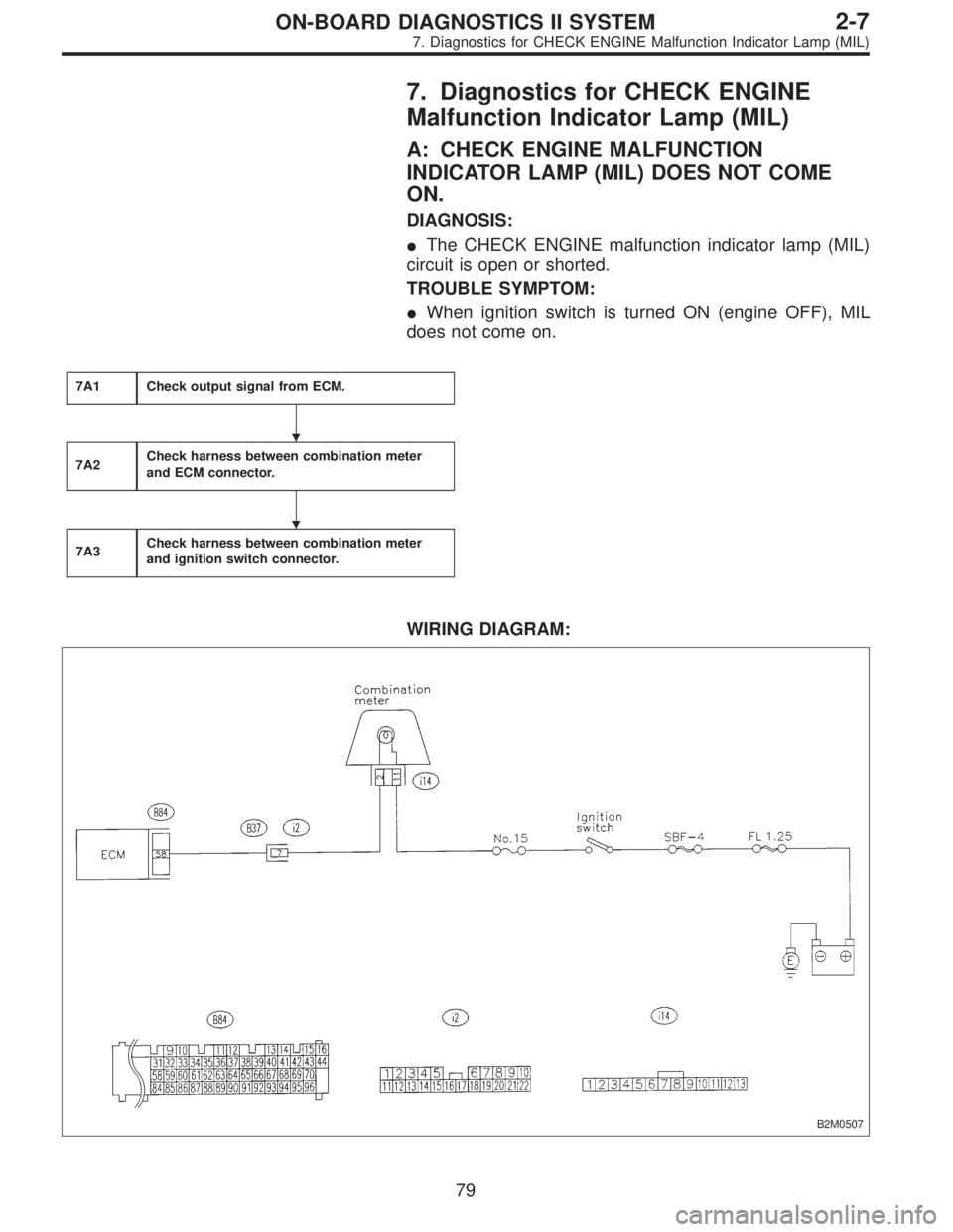
7. Diagnostics for CHECK ENGINE
Malfunction Indicator Lamp (MIL)
A: CHECK ENGINE MALFUNCTION
INDICATOR LAMP (MIL) DOES NOT COME
ON.
DIAGNOSIS:
�The CHECK ENGINE malfunction indicator lamp (MIL)
circuit is open or shorted.
TROUBLE SYMPTOM:
�When ignition switch is turned ON (engine OFF), MIL
does not come on.
7A1Check output signal from ECM.
7A2Check harness between combination meter
and ECM connector.
7A3Check harness between combination meter
and ignition switch connector.
WIRING DIAGRAM:
B2M0507
�
�
79
2-7ON-BOARD DIAGNOSTICS II SYSTEM
7. Diagnostics for CHECK ENGINE Malfunction Indicator Lamp (MIL)
Page 1848 of 2890
 Turn ignition switch to ON.
2) Measure voltage between ECM connector and chassis
ground.
: Connector & terminal
(B84) No. 58 (+) — Chassis ground (�):
I")
B2M0508A
7A1
CHECK OUTPUT SIGNAL FROM ECM.
1) Turn ignition switch to ON.
2) Measure voltage between ECM connector and chassis
ground.
: Connector & terminal
(B84) No. 58 (+) — Chassis ground (�):
Is the voltage less than 1 V?
: Go to step7A2.
: Go to next.
: Does the MIL come on when shaking or
pulling ECM connector and harness?
: Repair poor contact in ECM connector.
: Go to next.
: Is ECM connector correctly connected?
: Replace ECM.
: Repair connection of ECM connector.
B2M0763A
7A2CHECK HARNESS BETWEEN COMBINA-
TION METER AND ECM CONNECTOR.
1) Turn ignition switch to OFF.
2) Remove combination meter.
3) Disconnect connector from ECM and combination
meter.
4) Measure resistance of harness between ECM and com-
bination meter connector.
: Connector & terminal
(B84) No. 58 — (i14) No. 2:
Is resistance less than 1Ω?
: Go to next.
: Repair harness and connector.
NOTE:
In this case, repair the following:
�Open circuit in harness between ECM and combination
meter connector
�Poor contact in coupling connector (B37)
: Is there poor contact in combination meter
connector?
: Repair poor contact in combination meter connec-
tor.
: Go to step7A3.
80
2-7ON-BOARD DIAGNOSTICS II SYSTEM
7. Diagnostics for CHECK ENGINE Malfunction Indicator Lamp (MIL)

Note
Ignition SW ON
(Engine OFF)Engine ON (Idling)
AT diagnosis input signal B84 80Less than 1)More
than 4Less than 1)More
than 4Waveform
GND (sensors) B84 2")