Page 1695 of 2890
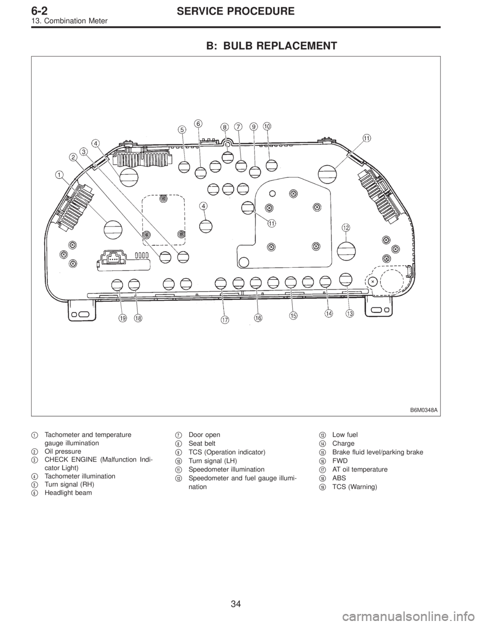
B: BULB REPLACEMENT
B6M0348A
�1Tachometer and temperature
gauge illumination
�
2Oil pressure
�
3CHECK ENGINE (Malfunction Indi-
cator Light)
�
4Tachometer illumination
�
5Turn signal (RH)
�
6Headlight beam�
7Door open
�
8Seat belt
�
9TCS (Operation indicator)
�
10Turn signal (LH)
�
11Speedometer illumination
�
12Speedometer and fuel gauge illumi-
nation�
13Low fuel
�
14Charge
�
15Brake fluid level/parking brake
�
16FWD
�
17AT oil temperature
�
18ABS
�
19TCS (Warning)
34
6-2SERVICE PROCEDURE
13. Combination Meter
Page 1738 of 2890
B3M0289
1) Disconnect connector from vehicle speed sensor 2.
2) Measure resistance between terminals of vehicle speed
sensor 2.
Terminals / Specified resistance:
No. 1—No. 2 / 350—450Ω
B3M0256
WARNING:
Be careful not to be caught up by the running wheels.
3) Set the vehicle on free roller, or lift-up the vehicle and
support with safety stands.
4) Drive the vehicle at speed greater than 20 km/h (12
MPH).
5) Measure voltage between terminals of vehicle speed
sensor 2.
Terminals / Specified voltage:
No. 1—No.2/5V,min. (AC range)
B3M0257
�Using an oscilloscope:
(1) Turn ignition switch to OFF.
(2) Set oscilloscope to vehicle speed sensor 2.
(3) Drive the vehicle at speed greater than 20 km/h (12
MPH).
(4) Measure signal voltage.
Specified voltage (V): 5 V, min.
B3M0254A
74
6-2DIAGNOSTICS
3. Combination Meter
Page 1751 of 2890

Door lock/unlock switch1
(INPUT)�Battery voltage is present when all doors")
C: CONTROL MODULE I/O SIGNAL
B6M0405
Content Terminal No.Measuring conditions and I/O signals
(Ignition switch ACC position)
Door lock/unlock switch1
(INPUT)�Battery voltage is present when all doors and rear gate (WAGON) are locked.
�“0”volt is present when one of the doors or rear gate (WAGON) is unlocked.
Key cylinder lock switch2
(INPUT)�“0”volt is present when key cylinder is turned to LOCK position.
�Battery voltage is present when key cylinder is in positions other than LOCK.
Tamper switch3
(INPUT)�Battery voltage is present when key cylinder switch is installed to key cylinder.
�“0”volt is present when key cylinder switch is removed from key cylinder.
Door switch4
(INPUT)�Battery voltage is present when all doors are closed.
�“0”volt is present when one of the doors is open.
Starter interrupt relay5
(OUTPUT)�Battery voltage is present when ignition switch is turned ACC or ON.
�“0”volt is present when security system is in alarm state.
Ignition switch (ACC)6
(INPUT)�Battery voltage is present when ignition switch is turned ACC or ON.
�“0”volt is present when ignition switch is turned OFF.
Security indicator light7
(OUTPUT)�Battery voltage is present when indicator light goes off.
�“0”volt is present when indicator light illuminates.
Power supply (back-up) 8 Battery voltage is constantly present.
Ground 9—
Engine hood switch10
(INPUT)�Battery voltage is present when engine hood is closed.
�“0”volt is present when engine hood is open.
Trunk lid switch (SEDAN)
Rear gate switch (WAGON)11
(INPUT)�Battery voltage is present when trunk lid or rear gate is closed.
�“0”volt is present when trunk lid or rear gate is open.
Headlight alarm relay12
(OUTPUT)�Battery voltage is present when ignition switch is turned ACC or ON.
�“0”volt and battery voltage repeats in alarm state. (Headlights flash intermittently
at 0.2 sec. ON and 0.6 sec. OFF intervals).
Horn relay13
(OUTPUT)�Battery voltage is present when ignition switch is turned ACC or ON.
�“0”volt and battery voltage repeats in alarm state. (Horn sounds intermittently at
0.2 sec. ON and 0.6 sec. OFF intervals.)
Key cylinder unlock switch14
(INPUT)�“0”volt is present when key cylinder is turned to UNLOCK position.
�Battery voltage is present when key cylinder is in positions other than UNLOCK.
Trunk lid key cylinder unlock
switch (SEDAN)15
(INPUT)�“0”volt is present when trunk lid key cylinder is turned to UNLOCK position.
�Battery voltage is present when trunk lid key cylinder is in positions other than
UNLOCK.
87
6-2DIAGNOSTICS
6. Security System
Page 1752 of 2890

D: BASIC DIAGNOSTICS PROCEDURE
Start security system check.
Fully open all door windows and turn ignition switch OFF.
Take key out of ignition, exit vehicle and lock driver’s door.
Indicator light illuminates.
OK The light flashes.
� The light does not
illuminate.
Check indicator harness.
Check security indicator light.
Check driver’s door key cylinder lock/unlock switch.
Check security control module.
Check whether switch input signal remains UNLOCK.
Check wiring harness.
Check switch input signals.
(Harnesses and switches separately)
(Tamper, door, hood, trunk and rear gate
switch)Check security control module.
Wait for 30 seconds.
Indicator light flashes at long intervals (0.2 sec. ON and 2.4 sec.
OFF).
OK
� Not OK
Check security control module.
Unlock driver’s door using the inside lock knob and open door.
The horn sounds and headlights flash intermittently at 0.2 sec. ON
and 0.6 sec. OFF intervals.
The engine will not start even if the ignition switch is turned to
START. Indicator lamp goes out.
OK Starter motor runs.
� All are not OK.
Check driver’s door switch.
Check wiring harness.
Check security control module.
� Horn is not OK.
Check horn
operation by
pushing horn pad
on steering wheel.
OK
� Not OK
Check horn.
Check horn relay.
Check security control module.
Check harness between horn relay and security control module.
� Headlights are not
OK.
Check headlights
operation by
turning light switch
ON/OFF.
OK
� Not OK
Check headlight
bulbs.
Check combination
switch.
Check headlight
relay.
Check starter interrupt relay.
Check wiring harness.
Check security control module.Check headlight alarm relay.
Check security control module.
Check wiring harness.
The alarm system continues to operate for 150 seconds.
OK Not OK
The horn and
headlights turn off.
The starter motor
does not run.
OK
� Not OK
Check security
control module.
Unlock the driver’s door using ignition key.
Continues to next step.
�
�
�
�
�
�
�
�
�
��
�
��
�
�
88
6-2DIAGNOSTICS
6. Security System
Page 1758 of 2890
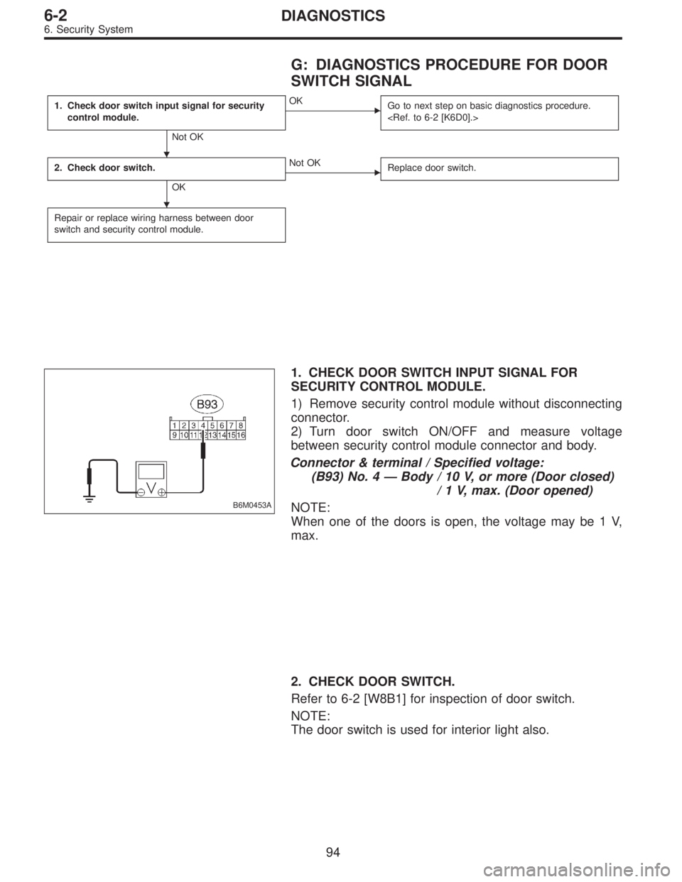
G: DIAGNOSTICS PROCEDURE FOR DOOR
SWITCH SIGNAL
1. Check door switch input signal for security
control module.
Not OK
�OK
Go to next step on basic diagnostics procedure.
2. Check door switch.
OK
�Not OK
Replace door switch.
Repair or replace wiring harness between door
switch and security control module.
B6M0453A
1. CHECK DOOR SWITCH INPUT SIGNAL FOR
SECURITY CONTROL MODULE.
1) Remove security control module without disconnecting
connector.
2) Turn door switch ON/OFF and measure voltage
between security control module connector and body.
Connector & terminal / Specified voltage:
(B93) No. 4—Body / 10 V, or more (Door closed)
/ 1 V, max. (Door opened)
NOTE:
When one of the doors is open, the voltage may be 1 V,
max.
2. CHECK DOOR SWITCH.
Refer to 6-2 [W8B1] for inspection of door switch.
NOTE:
The door switch is used for interior light also.
�
�
94
6-2DIAGNOSTICS
6. Security System
Page 1759 of 2890
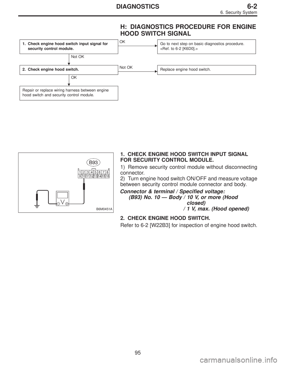
H: DIAGNOSTICS PROCEDURE FOR ENGINE
HOOD SWITCH SIGNAL
1. Check engine hood switch input signal for
security control module.
Not OK
�OK
Go to next step on basic diagnostics procedure.
2. Check engine hood switch.
OK
�Not OK
Replace engine hood switch.
Repair or replace wiring harness between engine
hood switch and security control module.
B6M0451A
1. CHECK ENGINE HOOD SWITCH INPUT SIGNAL
FOR SECURITY CONTROL MODULE.
1) Remove security control module without disconnecting
connector.
2) Turn engine hood switch ON/OFF and measure voltage
between security control module connector and body.
Connector & terminal / Specified voltage:
(B93) No. 10—Body / 10 V, or more (Hood
closed)
/ 1 V, max. (Hood opened)
2. CHECK ENGINE HOOD SWITCH.
Refer to 6-2 [W22B3] for inspection of engine hood switch.
�
�
95
6-2DIAGNOSTICS
6. Security System
Page 1760 of 2890
 OR REAR GATE
SWITCH (WAGON) SIGNAL
1. Check trunk lid switch (SEDAN) or rear gate
switch (WAGON) input signal for security
control module.
Not OK")
I: DIAGNOSTICS PROCEDURE FOR TRUNK
LID SWITCH (SEDAN) OR REAR GATE
SWITCH (WAGON) SIGNAL
1. Check trunk lid switch (SEDAN) or rear gate
switch (WAGON) input signal for security
control module.
Not OK
�OK
Go to next step on basic diagnostics procedure.
2. Check trunk lid switch (SEDAN) or rear gate
switch (WAGON).
OK
�Not OK
Replace trunk lid switch (or rear gate switch).
Repair or replace wiring harness between trunk lid
switch (or rear gate switch) and security control
module.
B6M0450A
1. CHECK TRUNK LID SWITCH (SEDAN) OR REAR
GATE SWITCH (WAGON) INPUT SIGNAL FOR
SECURITY CONTROL MODULE.
1) Remove security control module without disconnecting
connector.
2) Turn trunk lid switch (or rear gate switch) ON/OFF and
measure voltage between security control module connec-
tor and body.
Connector & terminal / Specified voltage:
(B93) No. 11—Body / 10 V, or more
(Lid or gate closed)
/ 1 V, max.
(Lid or gate opened)
2. CHECK TRUNK LID SWITCH (SEDAN) OR REAR
GATE SWITCH (WAGON).
Refer to 6-2 [W8B2], [W8B3] for inspection of trunk lid
switch/rear gate switch.
NOTE:
The trunk lid switch/rear gate switch is used for both trunk
room light/luggage room light.
�
�
96
6-2DIAGNOSTICS
6. Security System
Page 1762 of 2890

K: DIAGNOSTICS PROCEDURE FOR KEY
CYLINDER LOCK/UNLOCK SWITCH AND
TAMPER SWITCH SIGNAL
NOTE:
Key cylinder lock switch, key cylinder unlock switch and
tamper switch are combined as a unit.
1. Check key cylinder switch input signal for
security control module.
Not OK
�OK
Go to next step on basic diagnostics procedure.
2. Check key cylinder switch.
OK
�Not OK
Replace key cylinder switch.
Repair or replace wiring harness between key
cylinder switch and security control module.
B6M0499A
1. CHECK KEY CYLINDER SWITCH INPUT SIGNAL
FOR SECURITY CONTROL MODULE.
1) Remove security control module without disconnecting
connector.
2) Measure voltage between security control module con-
nector and body while turning each key cylinder with igni-
tion key.
Doors (RH and LH), and rear gate (WAGON)
Connector & terminal / Specified voltage:
(B93) No. 2—Body/1V,max. (LOCK position)
/ 10 V, or more (other than
LOCK position)
B6M0447A
(B93) No. 14—Body/1V,max. (UNLOCK position)
/ 10 V, or more (other than
UNLOCK position)
�
�
98
6-2DIAGNOSTICS
6. Security System
 Disconnect connector from vehicle speed sensor 2.
2) Measure resistance between terminals of vehicle speed
sensor 2.
Terminals / Specified resistance:
No. 1—No. 2 / 350—450Ω
B3M0256
W")