1996 SUBARU LEGACY turn signal
[x] Cancel search: turn signalPage 42 of 2890

ON-BOARD
DIAGNOSTICS
II
SYSTEM
ITscas1
2-7
3
.
Diagnosis
System
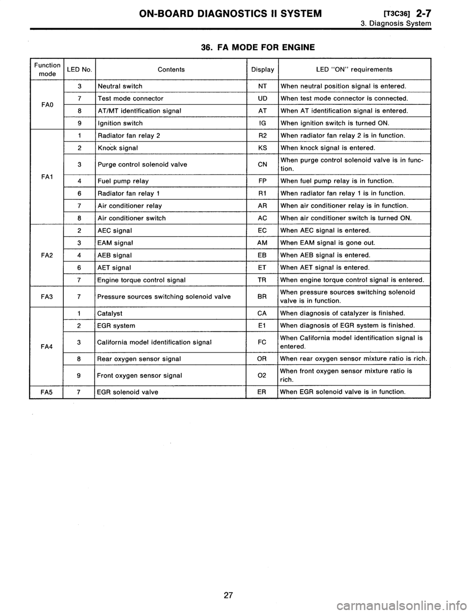
36
.
FA
MODE
FOR
ENGINE
Function
mode
LED
No
.
Contents
Display
LED
"ON"
requirements
3Neutral
switch
NT
When
neutralposition
signal
is
entered
.
7Test
mode
connector
UD
When
test
mode
connector
is
connected
.
FAO
8
AT/MT
identification
signal
AT
When
AT
identification
signal
is
entered
.
9
Ignition
switchIG
When
ignition
switch
is
turned
ON
.
1
Radiator
fan
relay
2
R2
When
radiator
fanrelay2
isin
function
.
2
Knock
signal
KS
When
knock
signal
is
entered
.
3
Purge
control
solenoid
valve
CNWhen
purge
control
solenoid
valve
is
in
func-
tion
.
FA1
4Fuel
pump
relay
FP
When
fuel
pump
relay
isin
function
.
6
Radiator
fanrelay
1
R1
When
radiator
fanrelay
1
isin
function
.
7
Air
conditioner
relay
ARWhen
air
conditioner
relay
isin
function
.
8
Air
conditioner
switch
ACWhen
air
conditioner
switch
is
turned
ON
.
2
AEC
signal
ECWhen
AEC
signal
is
entered
.
3
EAM
signal
AM
When
EAM
signal
is
gone
out
.
FA2
4
AEB
signal
EB
When
AEB
signal
is
entered
.
6
AET
signal
ET
When
AET
signal
is
entered
.
7
Engine
torque
control
signal
TR
When
engine
torque
control
signal
is
entered
.
FA3
7
Pressure
sources
switching
solenoid
valve
BR
When
pressure
sources
switching
solenoid
valve
is
in
function
.
1
Catalyst
CA
When
diagnosis
of
catalyzer
is
finished
.
2
EGR
system
E1
When
diagnosis
of
EGR
system
is
finished
.
FA4
3
California
model
identification
signal
FC
When
California
model
identification
signal
is
entered
.
8
Rear
oxygen
sensor
signal
OR
When
rear
oxygen
sensor
mixture
ratio
is
rich
.
9Front
oxygen
sensor
signal
02
When
front
oxygen
sensor
mixture
ratio
is
rich
.
FA5
7
EGR
solenoid
valve
ER
When
EGR
solenoid
valve
is
in
function
.
27
Page 43 of 2890
![SUBARU LEGACY 1996 Service Repair Manual
Z-T
[T3C37]
ON-BOARD
DIAGNOSTICS
II
SYSTEM
3
.
Diagnosis
System
LED
No
.
Signal
name
Display
1
-
-
2
-
-
3Neutralswitch
NT
4
--
5
--
s
--
7
Test
mode
connector
LID
8
Identification
of
AT
mo SUBARU LEGACY 1996 Service Repair Manual
Z-T
[T3C37]
ON-BOARD
DIAGNOSTICS
II
SYSTEM
3
.
Diagnosis
System
LED
No
.
Signal
name
Display
1
-
-
2
-
-
3Neutralswitch
NT
4
--
5
--
s
--
7
Test
mode
connector
LID
8
Identification
of
AT
mo](/manual-img/17/57433/w960_57433-42.png)
Z-T
[T3C37]
ON-BOARD
DIAGNOSTICS
II
SYSTEM
3
.
Diagnosis
System
LED
No
.
Signal
name
Display
1
-
-
2
-
-
3Neutralswitch
NT
4
--
5
--
s
--
7
Test
mode
connector
LID
8
Identification
of
AT
model
AT
9
Ignition
switchIG
r
0
-
-
NT
--
-
LID
AT
IG
-
ooooa
LEDNo
.
Signal
name
Display
1
Radiator
fan
relay
2
R2
2
Knock
signal
KS
Purge
control
solenoid
valve
CN
4
Fuel
pump
relay
FP
5
-
-
6
Radiator
fan
relay
1
R1
7
A/C
relay
AR
8
A/C
switch
AC
9
--
o
--
R2
KSCN
FP
-
R1
ARAC
--
37
.
FUNCTION
MODE
:
FAO
-
ON
H
OFF
SIGNAL
-
Requirement
for
LED
"ON"
.
LED
No
.
3
Shift
position
is
in
"P"or
"N"
.
LED
No
.
7
Test
mode
connector
is
connected
.
LED
No
.
8
Vehicle
is
AT
model
.
LED
No
.
9
Ignition
switch
is
turned
ON
.
38
.
FUNCTION
MODE
:
FA1
-
ON
H
OFF
SIGNAL
-
Requirement
for
LED
"ON"
.
LEDNo
.
1
Radiator
fan
relay
2
is
turned
ON
.
LEDNo
.
2
Engine
is
knocking
.
LED
No
.
3
Purge
control
solenoid
valve
is
in
function
.
LED
No
.
4
Fuel
pump
relay
is
turned
ON
.
LED
No
.
6
Radiator
fan
relay
1
is
turned
ON
.
LED
No
.
7
A/C
relay
is
turned
ON
.
LED
No
.
8
A/C
switch
is
turned
ON
.
NOTE
:
9
When
LED
No
.
1,3,
4,
6
and
7
blinks
with
the
test
mode
connector
connected
and
the
ignition
switch
turned
to
ON,
the
corresponding
part
is
functioning
properly
.
e
When
LED
No
.
4
illuminates
for
only
2
seconds
after
the
ignition
switch
is
turned
to
ON,
(and
then
goes
out),
the
corresponding
part
is
functioningproperly
.
28
Page 44 of 2890

ON-BOARD
DIAGNOSTICS
II
SYSTEM
[rscaoi
2-7
3
.
Diagnosis
System
LEDNo
.
Signal
name
Display
--
2
AEC
signal
EC
3
EAM
signal
AM
4
AEB
signal
EB
5
-
-
6
AET
signal
ET
Engine
torque
control
signal
TR
a
-
-
9
--
0~
--
-
EC
AM
EB
-
ET
TR
---
LED
No
.
Signal
name
Display
1
--
2
--
3
-
-
4
-
-
5
--
s
--
Pressure
sources
switching
solenoid
valve
8
--
9
--
0
-
-
-
BR
-
-
-
mmmmm
39
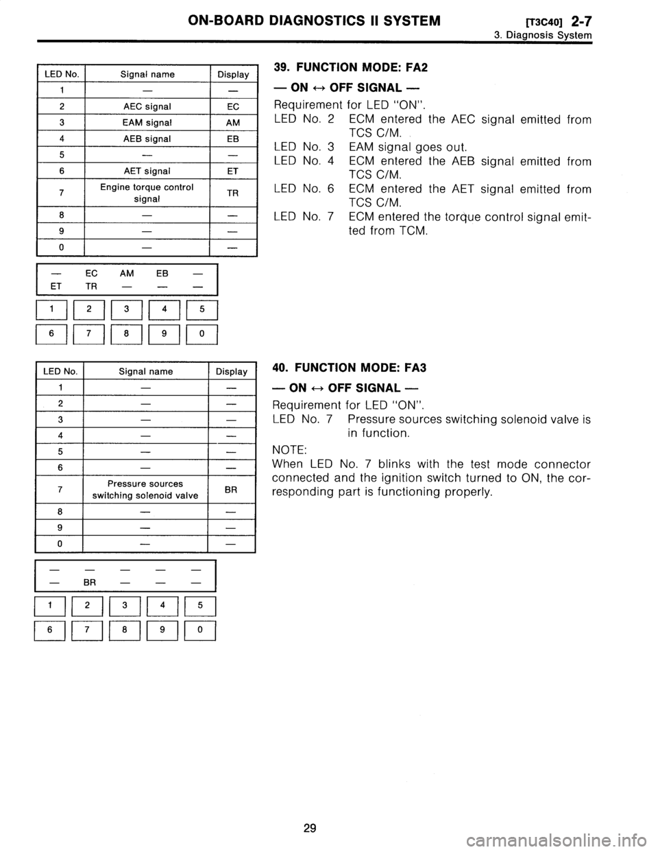
.
FUNCTION
MODE
:
FA2
-
ON
H
OFF
SIGNAL
-
Requirement
for
LED
"ON"
.
LED
No
.
2
ECM
entered
the
AEC
signal
emitted
from
TCS
C/M
.
LED
No
.
3
EAM
signal
goes
out
.
LED
No
.
4
ECM
entered
the
AEB
signal
emitted
from
TCS
C/M
.
LED
No
.
6
ECM
entered
the
AET
signal
emitted
from
TCS
C/M
.
LEDNo
.
7
ECM
entered
the
torque
control
signal
emit-
ted
from
TCM
.
40
.
FUNCTION
MODE
:
FA3
-
ON
H
OFF
SIGNAL
-
Requirement
for
LED
"ON"
.
LEDNo
.
7
Pressure
sources
switchingsolenoid
valve
is
in
function
.
NOTE
:
When
LED
No
.
7
blinks
with
the
test
mode
connector
connected
and
the
ignition
switch
turned
to
ON,
the
cor-
responding
part
is
functioning
properly
.
29
Page 45 of 2890
![SUBARU LEGACY 1996 Service Repair Manual 2-7
[T3C41]
ON-BOARD
DIAGNOSTICS
II
SYSTEM
3
.
Diagnosis
System
LED
No
.
Signal
name
Display
1
Catalyst
CA
2
EGR
system
E1
California
model
identification
signal
FC
4
--
5
--
s
--
--
8
Rear
SUBARU LEGACY 1996 Service Repair Manual 2-7
[T3C41]
ON-BOARD
DIAGNOSTICS
II
SYSTEM
3
.
Diagnosis
System
LED
No
.
Signal
name
Display
1
Catalyst
CA
2
EGR
system
E1
California
model
identification
signal
FC
4
--
5
--
s
--
--
8
Rear](/manual-img/17/57433/w960_57433-44.png)
2-7
[T3C41]
ON-BOARD
DIAGNOSTICS
II
SYSTEM
3
.
Diagnosis
System
LED
No
.
Signal
name
Display
1
Catalyst
CA
2
EGR
system
E1
California
model
identification
signal
FC
4
--
5
--
s
--
--
8
Rear
oxygen
sensor
signal
OR
9Front
oxygen
sensor
signal
02
o
-
1
CA
E1
FC
--
--
OR
02
-
LEDNo
.
Signal
name
Display
1
--
2
--
3
--
4
--
5
--
s
--
7
EGR
solenoid
valve
ER
8
--
9
--
~1
-
I
-
1
-
ER
--
-
ooaoo
00000
41
.
FUNCTION
MODE
:
FA4
-
ON
<-->
OFF
SIGNAL
-
Requirement
for
LED
"ON"
.
LED
No
.
1
Diagnosis
of
catalyzer
is
finished
.
LED
No
.
2Diagnosis
of
EGR
system
is
finished
.
LED
No
.
3
Vehicle
is
except
California
model
.
LED
No
.
8
Rear
oxygen
sensor
mixture
ratio
is
rich
.
LED
No
.
9
Front
oxygen
sensor
mixture
ratio
is
rich
.
42
.
FUNCTION
MODE
:
FA5
-
ON
H
OFF
SIGNAL
-
Requirement
for
LED
"ON"
.
LED
No
.
7
EGR
solenoid
valve
is
in
function
.
NOTE
:
When
LEDNo
.
7
blinks
with
the
test
mode
connector
connected
and
the
ignition
switch
turned
to
ON,
the
cor-
responding
part
is
functioning
properly
.
30
Page 52 of 2890
![SUBARU LEGACY 1996 Service Repair Manual
ON-BOARD
DIAGNOSTICS
II
SYSTEM
[T3C61]
2-7
3
.
Diagnosis
System
LED
No
.
Signal
name
Display
1
FWD
switch
FF
2
Kick-down
switch
KD
3
-
-
4
-
-
5
Brake
switch
BR
6
ABS
switch
AB
7
Cruise
cont SUBARU LEGACY 1996 Service Repair Manual
ON-BOARD
DIAGNOSTICS
II
SYSTEM
[T3C61]
2-7
3
.
Diagnosis
System
LED
No
.
Signal
name
Display
1
FWD
switch
FF
2
Kick-down
switch
KD
3
-
-
4
-
-
5
Brake
switch
BR
6
ABS
switch
AB
7
Cruise
cont](/manual-img/17/57433/w960_57433-51.png)
ON-BOARD
DIAGNOSTICS
II
SYSTEM
[T3C61]
2-7
3
.
Diagnosis
System
LED
No
.
Signal
name
Display
1
FWD
switch
FF
2
Kick-down
switch
KD
3
-
-
4
-
-
5
Brake
switch
BR
6
ABS
switch
AB
7
Cruise
control
set
CR
8
Power
switch
PW
9
--
-
I
10
-
I
-
FF
KD
--
BR
ABCR
PW
--
10
LEDNo
.
Signal
name
Display
1
N/P
range
switch
NP
2
R
range
switch
RR
3
D
range
switch
RD
43
range
switch
R3
52
range
switch
R2
6
1
range
switch
R1
7
Diagnosis
switch
SS
s
--
s
-
-
10
-
-
NPRRRDR3
R2
R1
SS
---
oaaoo
0000
,o
60
.
FUNCTION
MODE
:
FAO
-
ON
H
OFF
SIGNAL
-
Requirement
for
LED
"ON"
.
LED
No
.
1
Fuse
is
installed
in
FWD
switch
.
LED
No
.
2
Kick-down
switch
is
turned
ON
.
(Not
equipped)
LED
No
.
5
Brake
pedal
is
depressed
.
LED
No
.
6
ABS
signal
is
entered
.
LED
No
.
7
Cruise
control
is
set
.
LED
No
.
8
Power
switch
is
turned
ON
.
(Not
equipped)
61
.
FUNCTION
MODE
:
FA1
-
ON
H
OFF
SIGNAL
-
Requirement
for
LED
"ON"
.
LED
No
.
1
"N"
or
"P"
range
is
selected
.
LED
No
.
2"R"
range
is
selected
.
LED
No
.
3
"D"
range
is
selected
.
LEDNo
.
4
"3"
range
is
selected
.
LEDNo
.
5
"2"
range
is
selected
.
LEDNo
.
6
"1"
range
is
selected
.
LEDNo
.
7
Diagnosis
connector
is
connected
.
37
Page 60 of 2890

2-7
tT5o21
ON-BOARD
DIAGNOSTICS
II
SYSTEM
5
.
Specified
Data
CT
il
Signal
(V)
Content
onnector
erm
na
I9nition
SW
ON
Note
No
.
No
.
(Engine
OFF)Engine
ON
(Idling)
Rear
oxygen
sensor
B84
37
0-1
.0
0-1
.0
-
heater
signal
AT
diagnosis
input
B84
80
Less
than
1
.-
.
More
Less
than
1
+-+
MoreWaveform
signal
than4
than
4
GND
(sensors)
B84
200
0
-
i
B
469
GND
(
njectors)
80
0
-
95
GND
(ignition
system)
B84
940
0
-
ND
l
B
4
19
(powersupp
y)
G
800
-
46
17
GND
(control
systems)
B84
00
-
18
GND
(oxygen
sensor
B84
4200
heater)
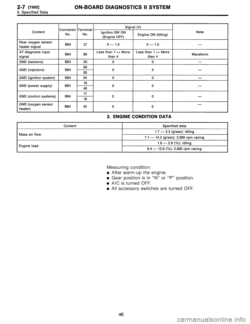
2
.
ENGINECONDITION
DATA
Content
Specified
data
i
fl
M
1.7
-
3
.3
(g/sec)
:
Idling
r
ass
a
ow
7
.1
-
14
.2
(g/sec)
:
2,500
rpm
racing
E
il
d
1.6
-
2
.9
(%)
:
Idling
ng
neoa
6
.4
-
12
.8
(%)
:
2,500
rpm
racing
Measuring
condition
:
"
After
warm-up
theengine
.
"
Gear
position
is
in
"N"
or
"P"
position
.
"
A/C
is
turned
OFF
.
All
accessory
switches
are
turned
OFF
.
46
Page 176 of 2890

6-3
[0602
WIRING
DIAGRAM
6
.
Wiring
Diagram
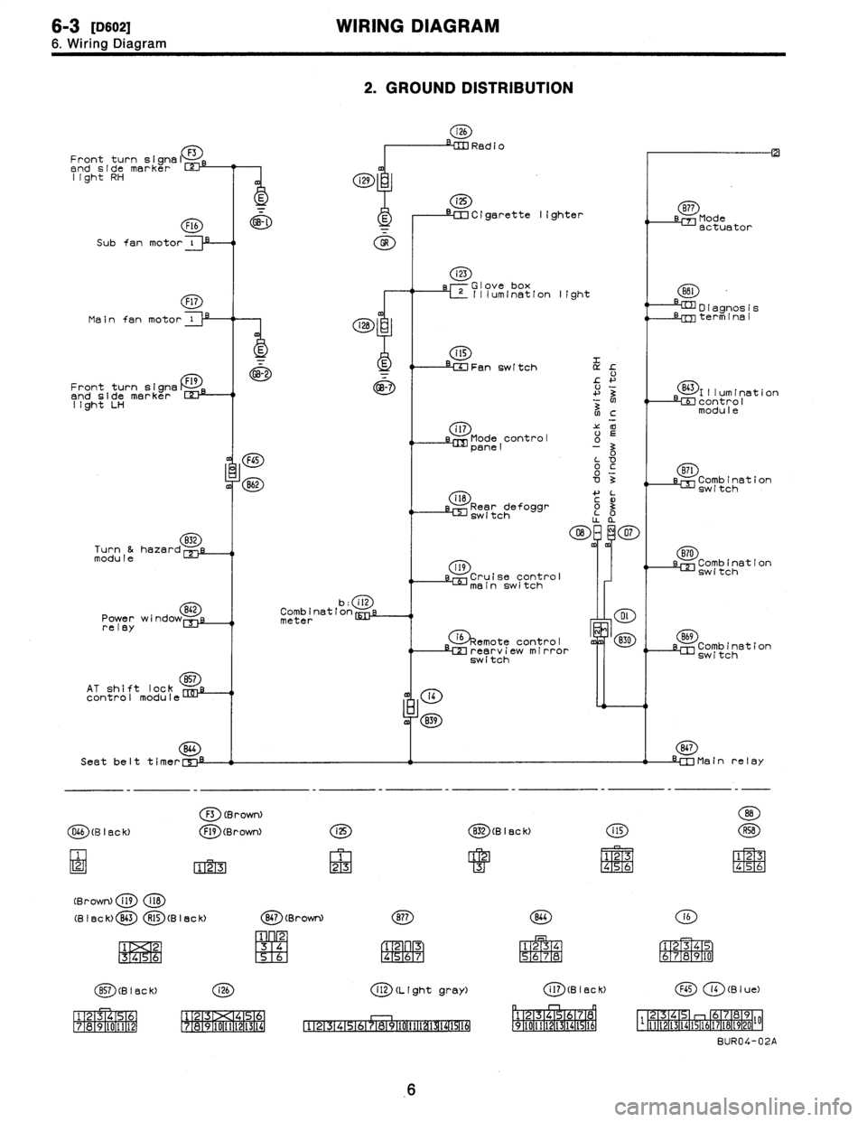
2
.
GROUND
DISTRIBUTION
i26
RedioFront
turn
signal
F3
end
side
marker
rm
light
RH
i
i29
i25
~~--
--
a
--~~
Cigarette
lighter
sB77
Mode
F16
~-~
E
I
actuator
Subfan
motor
i
O
Main
fan
motor
Front
turn
signs
Dend
side
marker
123-1
light
LH
832
Turn
&hazardmodule
Power
wi
relay
AT
shift
lock
857
control
module
(28
:
E
GB-2
FGS
B62
b
:
ill
Combination
meter
(4
m
839
Seat
belt
t
i
mer
C',"-i
F3
(BrowN
O66
(B
I
BC
k)
F19
(Brown)
123
(Brown)
fig
118
(B
I
ac
k)
B43
R15
(B
I
ec
k)
1
2
1
3
1
4
151
6
i
25
1
23
i23
rGlove
box
L~
Illum(nation
light
Fan
switch
L
!-
+'
3
N
NC
i
l7'Z
00
Mode
control
o
panel
0o
~c
'0o
3
il8
4-
L
3
Rear
defoggr
~
o3
switch
O
~m~
07
m
119
Cruise
control
mainswitch
G)§emote
ontro
I
c
LM
rearv
i
e
irror
switch
(g)
(B
I
ec
k)
CD
1
23
4
M
S6
(g)(Brown)
(~D
1
23
[96
R4
;6R7
(~D(BISCK)
(~D
ff~
1516-111
12131><14151
111213
171a191101111121
1718191101111121131141
CD
(L
(ght
gray)
4
'
:F
151617
P911011111~~
D
I
agnos
1
s
Lrm
term
1
na
I
(E~)l
II
um
I
nat
1
on
LEE
contro
I
modu
I
e
(ED
LM
Combination
switch
870
sl=
Combination
switch
B69
Combination
switch
867
-IM
Main
relay
141516
(E)
(a)
1
234
S6JR8
161
r
1
E319
1101
(aD
(B
I
ac
K)
(B
I
u
e)
p
r-1
n
~1
1
F2-1[3
1
f41516
1
7a
0
1
2-
F
-
1q,
[3
46
112-2TI-3114115116117118119120
I'F
BUR04-02A
6
Page 195 of 2890
![SUBARU LEGACY 1996 Service Repair Manual
AUTOMATIC
TRANSMISSION
AND
DIFFERENTIAL
[T7H3]
3-2
7
.
Diagnostic
Chart
with
Trouble
Code
B54
123456
7
8
9
01112
D
L
.0
Q
0>
B3M02248
B54
161514
3
H87
1211
10
9
D
_E)VSj
83M0222B
Data
link SUBARU LEGACY 1996 Service Repair Manual
AUTOMATIC
TRANSMISSION
AND
DIFFERENTIAL
[T7H3]
3-2
7
.
Diagnostic
Chart
with
Trouble
Code
B54
123456
7
8
9
01112
D
L
.0
Q
0>
B3M02248
B54
161514
3
H87
1211
10
9
D
_E)VSj
83M0222B
Data
link](/manual-img/17/57433/w960_57433-194.png)
AUTOMATIC
TRANSMISSION
AND
DIFFERENTIAL
[T7H3]
3-2
7
.
Diagnostic
Chart
with
Trouble
Code
B54
123456
7
8
9
01112
D
L
.0
Q
0>
B3M02248
B54
161514
3
H87
1211
10
9
D
_E)VSj
83M0222B
Data
link
connector
(for
Subaru
select
monitor
and
OBD-II
general
scan
tool)
/
'
/
i
Data
link
connector
(for
Subaru
select
monitor
\
,only)
ls%y~
x~/
OBD0145A
I
AFM
(F15)
0
.6V
B3M0370
2
.
CHECK
HARNESS
CONNECTOR
BETWEEN
TCM
AND
ECM
.
1)
Turn
ignition
switch
to
OFF
.
2)
Disconnect
connectors
from
TCM
and
ECM
.
3)
Measure
resistance
of
harness
connector
between
TCM
and
ECM
.
Connector
&
terminal
I
Specifiedresistance
:
(B54)
No
.
9
-
(B84)
No
.
47
l
1
S2,
orless
4)
Measure
resistance
of
harness
connector
between
TCM
and
body
to
make
sure
that
circuit
does
not
short
.
Connector
&
terminal
/
Specified
resistance
:
(854)
No
.
9
-
Body
11
MSZ,
or
more
3
.
CHECK
INPUT
SIGNAL
FOR
TCM
.
1)
Connect
connectors
to
TCM
and
ECM
.
2)
Start
the
engine
.
(engine
idling
after
warm-up)
3)
Measure
signal
voltage
between
TCM
connector
termi-
nal
and
body
.
Connector
&
terminal
/
Specified
voltage
:
Engine
warm-up
;
(B54)
No
.
9
-
Body
l
0
.5
-
1
.22
V
9
Using
Subaru
select
monitor
:
(1)
Connect
connectors
to
TCM
and
ECM
.
(2)
Turn
ignition
switch
to
OFF
.
(3)
Connect
the
Subaru
select
monitor
to
data
link
connector
.
(4)
Turn
ignition
switch
to
ON
and
Subaru
select
monitor
switch
to
ON
.
(5)
Start
andwarm-up
the
engine
.
(6)
Read
data
onSubaru
select
monitor
.
(7)
Designate
mode
using
function
key
.
Function
mode
:
F15
SPECIFIED
DATA
:
0
.5
-
1
.22
V
(Engine
warm-up)
5