Page 2013 of 2890
WIRING DIAGRAM:
�LHD Model
B2M0569
WIRING DIAGRAM:
�RHD Model
B2M0795
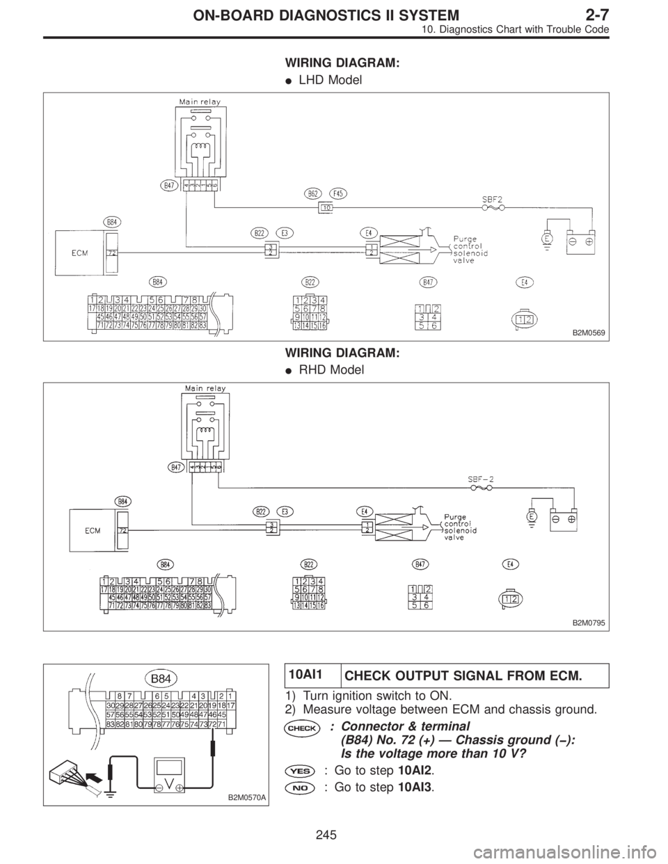
B2M0570A
10AI1
CHECK OUTPUT SIGNAL FROM ECM.
1) Turn ignition switch to ON.
2) Measure voltage between ECM and chassis ground.
: Connector & terminal
(B84) No. 72 (+)—Chassis ground (�):
Is the voltage more than 10 V?
: Go to step10AI2.
: Go to step10AI3.
245
2-7ON-BOARD DIAGNOSTICS II SYSTEM
10. Diagnostics Chart with Trouble Code
Page 2020 of 2890
 Turn ignition switch to ON.
2) Measure voltage between ECM and chassis ground.
: Connector & terminal
(B84) No. 35 (+)—Chassis ground (�):
Is the volt")
H2M1370B
10AJ1
CHECK OUTPUT SIGNAL FROM ECM.
1) Turn ignition switch to ON.
2) Measure voltage between ECM and chassis ground.
: Connector & terminal
(B84) No. 35 (+)—Chassis ground (�):
Is the voltage more than 10 V?
: Go to step10AJ2.
: Go to step10AJ3.
H2M1370B
10AJ2CHECK HARNESS BETWEEN VENT
CONTROL SOLENOID VALVE AND ECM
CONNECTOR.
1) Turn ignition switch to OFF.
2) Disconnect connector from vent control solenoid valve.
3) Turn ignition switch to ON.
4) Measure voltage between ECM and chassis ground.
: Connector & terminal
(B84) No. 35 (+)—Chassis ground (�):
Is the voltage more than 10 V?
: Repair short circuit in harness and replace ECM.
NOTE:
The harness between ECM and vent control solenoid valve
is in short circuit.
: Go to next step 5).
H2M1238A
5) Turn ignition switch to OFF.
6) Measure resistance between vent control solenoid
valve terminals.
: Terminals
No. 1—No. 2:
Is the resistance less than 1Ω?
: Replace vent control solenoid valve and ECM.
: Go to next.
: Is there poor contact in ECM connector?
: Repair poor contact in ECM connector.
: Replace ECM.
252
2-7ON-BOARD DIAGNOSTICS II SYSTEM
10. Diagnostics Chart with Trouble Code
Page 2026 of 2890
 Turn ignition switch to OFF.
2) Remove fuel filler cap.
3) Install fuel filler cap.
4) Connect Subaru Sel")
OBD0145A
10AK1CONNECT SUBARU SELECT MONITOR
OR THE OBD-II GENERAL SCAN TOOL,
AND READ DATA.
1) Turn ignition switch to OFF.
2) Remove fuel filler cap.
3) Install fuel filler cap.
4) Connect Subaru Select Monitor or the OBD-II general
scan tool to data link connector.
5) Turn ignition switch to ON and Subaru Select Monitor or
the OBD-II general scan tool switch to ON.
H2M1326
6) Read the data on Subaru Select Monitor or the OBD-II
general scan tool.
�Subaru Select Monitor
Designate mode using function key.
Function mode: F43
�F43: Display shows pressure signal value sent from fuel
tank pressure sensor.
: Is the value less than�2.8 kPa in function
mode F43?
: Go to step10AK2.
: Go to next.
H2M1326
: Is the value more than 2.8 kPa in function
mode F43?
: Go to step10AK4.
: Repair harness and connector.
NOTE:
In this case, repair the following:
�Open or short circuit in harness between fuel tank pres-
sure sensor and ECM connector
�Poor contact in coupling connectors (B97, and B98 (LHD
only))
�Poor contact in fuel tank pressure sensor
�Poor contact in ECM connector
�OBD-II general scan tool
For detailed operation procedures, refer to the OBD-II Gen-
eral Scan Tool Instruction Manual.
258
2-7ON-BOARD DIAGNOSTICS II SYSTEM
10. Diagnostics Chart with Trouble Code
Page 2039 of 2890
 Turn ignition switch to ON.
2) Start engine, and idle it.
: Is there a fault in air intake system?
NOTE:
Check the following items.
�Loose installation of intake mani")
10AN1
CHECK AIR INTAKE SYSTEM.
1) Turn ignition switch to ON.
2) Start engine, and idle it.
: Is there a fault in air intake system?
NOTE:
Check the following items.
�Loose installation of intake manifold, idle air control sole-
noid valve and throttle body
�Cracks of intake manifold gasket, idle air control sole-
noid valve gasket and throttle body gasket
�Loose connections and cracks of idle air control solenoid
valve by-pass hoses
�Disconnections of vacuum hoses
: Repair or replace air intake system.
: Go to step10AN2.
B2M0576A
10AN2
CHECK OUTPUT SIGNAL FROM ECM.
1) Turn ignition switch to ON.
2) Measure voltage between ECM and chassis ground.
: Connector & terminal
(B84) No. 13 (+)—Chassis ground (�):
Is the voltage more than 3 V?
: Go to next.
: Go to step10AN4.
: Connector & terminal
(B84) No. 14 (+)—Chassis ground (�):
Is the voltage more than 3 V?
: Go to next step 3).
: Go to step10AN4.
271
2-7ON-BOARD DIAGNOSTICS II SYSTEM
10. Diagnostics Chart with Trouble Code
Page 2059 of 2890
 No. 6—No. 4
�Is the resistance less than 1Ωin“2”
position?
�Is the resistance more than 1 MΩin other
positions?
: Go to next.
:Goto.
: Connector & terminal
(T3) N")
: Connector & terminal
(T3) No. 6—No. 4
�Is the resistance less than 1Ωin“2”
position?
�Is the resistance more than 1 MΩin other
positions?
: Go to next.
:Goto.
: Connector & terminal
(T3) No. 5—No. 4
�Is the resistance less than 1Ωin“1”
position?
�Is the resistance more than 1 MΩin other
positions?
: Go to step10AT3.
:Goto.
: Is there faulty connection in the selector
cable?
: Repair connection of selector cable.
: Replace inhibitor switch.
OBD0595A
10AT3
CHECK INPUT SIGNAL FOR TCM.
1) Turn ignition switch to OFF.
2) Connect connector to TCM and transmission.
3) Turn ignition switch to ON.
4) Measure voltage between TCM and chassis ground.
: Connector & terminal
(B56) No. 9 (+)—Chassis ground (�):
�Is the voltage less than1Vin“P”and
“N”positions?
�Is the voltage more than8Vinother
positions?
: Go to next.
:Goto.
: Connector & terminal
(B56) No. 10 (+)—Chassis ground (�):
�Is the voltage less than1Vin“R”posi-
tion?
�Is the voltage more than6Vinother
positions?
: Go to next.
:Goto.
: Connector & terminal
(B56) No. 8 (+)—Chassis ground (�):
�Is the voltage less than1Vin“N”and
“P”positions?
�Is the voltage more than8Vinother
positions?
: Go to next.
:Goto.
291
2-7ON-BOARD DIAGNOSTICS II SYSTEM
10. Diagnostics Chart with Trouble Code
Page 2084 of 2890
 Turn ignition switch to ON.
2) Measure voltage between ECM and chassis ground.
: Connector & terminal
(B84) No. 82 (+)—Chassis ground (�):
Is the voltag")
B2M0589A
10BJ1
CHECK INPUT SIGNAL FOR ECM.
1) Turn ignition switch to ON.
2) Measure voltage between ECM and chassis ground.
: Connector & terminal
(B84) No. 82 (+)—Chassis ground (�):
Is the voltage between 4.5 and 5.5 V in neu-
tral position?
: Go to next.
: Go to step10BJ2.
B2M0589A
: Connector & terminal
(B84) No. 82 (+)—Chassis ground (�):
Is the voltage less than1Vinother posi-
tions?
: Go to next.
: Go to step10BJ2.
: Is there poor contact in ECM connector?
: Repair poor contact in ECM connector.
: Replace ECM.
OBD0469A
10BJ2
CHECK NEUTRAL POSITION SWITCH.
1) Turn ignition switch to OFF.
2) Disconnect connector from transmission harness.
3) Measure resistance between transmission harness and
connector terminals.
: Connector & terminal
(T2) No. 1—No. 2:
Is the resistance more than 1 MΩin neutral
position?
: Go to next.
: Repair short circuit in transmission harness or
replace neutral position switch.
: Connector & terminal
(T2) No. 1—No. 2:
Is the resistance less than 1Ωin other posi-
tions?
: Go to step10BJ3.
: Repair open circuit in transmission harness or
replace neutral position switch.
316
2-7ON-BOARD DIAGNOSTICS II SYSTEM
10. Diagnostics Chart with Trouble Code
Page 2087 of 2890
WIRING DIAGRAM:
B2M0592
B2M0593A
10BK1
CHECK INPUT SIGNAL FOR ECM.
1) Turn ignition switch to ON.
2) Measure voltage between ECM and chassis ground.
: Connector & terminal
(B84) No. 82 (+)—Chassis ground (�):
Is the voltage less than1Vin“N”and“P”
positions?
: Go to next.
: Go to step10BK2.
B2M0593A
: Connector & terminal
(B84) No. 82 (+)—Chassis ground (�):
Is the voltage between 4.5 and 5.5 V in other
positions?
: Go to next.
: Go to step10BK2.
: Is there poor contact in ECM connector?
: Repair poor contact in ECM connector.
: Replace ECM.
319
2-7ON-BOARD DIAGNOSTICS II SYSTEM
10. Diagnostics Chart with Trouble Code
Page 2092 of 2890
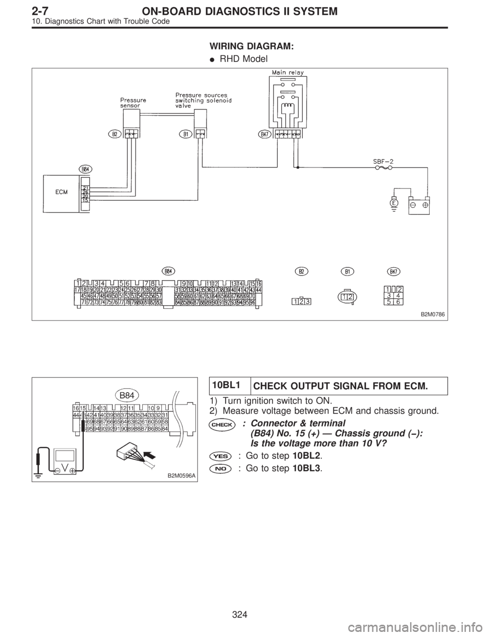
WIRING DIAGRAM:
�RHD Model
B2M0786
B2M0596A
10BL1
CHECK OUTPUT SIGNAL FROM ECM.
1) Turn ignition switch to ON.
2) Measure voltage between ECM and chassis ground.
: Connector & terminal
(B84) No. 15 (+)—Chassis ground (�):
Is the voltage more than 10 V?
: Go to step10BL2.
: Go to step10BL3.
324
2-7ON-BOARD DIAGNOSTICS II SYSTEM
10. Diagnostics Chart with Trouble Code
 Turn ignition switch to ON.
2) Measure voltage between ECM and chassis ground.
: Connector & terminal
(B84) No. 82 (+)—Chassis g")