Page 1024 of 2890
 Check for oil leakage.
2) Move the piston rod up and down to")
C: INSPECTION
Check the disassembled parts for cracks, damage and
wear, and replace with new parts if defective.
G4M0508
1. DAMPER STRUT
1) Check for oil leakage.
2) Move the piston rod up and down to check its operates
smoothly without any binding.
3) Play of piston rod
Measure the play as follows:
Fix outer shell and fully extend the rod. Set a dial gauge at
the end of the rod: L [10 mm (0.39 in)], then apply a force
of W [20 N (2 kg, 4 lb)] to threaded portion. With the force
of 20 N (2 kg, 4 lb) applied, read dial gauge indication: P
1.
Apply a force of 20 N (2 kg, 4 lb) in the opposite direction
of“W”, then read dial gauge indication: P
2. The free play
is determined by the following equation:
Play = P
1,P2
Limit of play:
Less than 0.8 mm (0.031 in)
If the play is greater, replace the strut with new one.
2. STRUT MOUNT
Check rubber part for wear, cracks and deterioration, and
replace it with new one if defective.
3. DUST COVER
If any cracks or damage are found, replace it with new one.
4. COIL SPRING
When vehicle posture is uneven, although there are no
considerable reasons like tire puncture, uneven loading,
etc., check coil spring and spring seats for cracks,
deformation, etc., and replace it with a new one if defective.
5. HELPER
Replace it with new one if cracked or damaged.
23
4-1SERVICE PROCEDURE
4. Front Strut
Page 1025 of 2890
 Before installing coil spring, strut mount, etc., on the
strut, check for the presence of air in the dampening force
generating mechanism of the strut since air prevents
proper dampenin")
D: ASSEMBLY
1) Before installing coil spring, strut mount, etc., on the
strut, check for the presence of air in the dampening force
generating mechanism of the strut since air prevents
proper dampening force from being produced.
2) Checking for the presence of air
(1) Place the strut vertically with the piston rod facing
upward.
(2) Move the piston rod to the center of its entire
stroke.
(3) While holding the piston rod end with finger-tips,
move the rod up and down.
(4) If the piston rod moves at least 10 mm (0.39 in) in
step (3), purge air from the strut.
3) Air purging procedure
(1) Place the strut vertically with the piston rod facing
upward.
(2) Fully extend the piston rod.
(3) With the piston rod fully extended, place the piston
rod side down. The strut must stand vertically.
(4) Fully contract the piston rod.
(5) Repeat 3 or 4 times steps (1) through (4) above.
NOTE:
After completely purging air from the strut, be sure to place
the strut with the piston rod facing upward. If it is laid down,
check for entry of air in the strut as outlined under item 2)
above.
B4M0568A
4) Using a coil spring compressor, compress the coil
spring.
NOTE:
Make sure that the vertical installing direction of coil spring
is as shown in figure.
G4M0510
5) Set the coil spring correctly so that its end face fits well
into the spring seat as shown.
6) Install helper and dust cover to the piston rod.
24
4-1SERVICE PROCEDURE
4. Front Strut
Page 1026 of 2890
 Pull the piston rod fully upward, and install rubber seat
and spring seat.
NOTE:
Ensure that upper spring seat is positioned with“OUT”
mark facing outward.
8) Install strut mount to the")
G4M0511
7) Pull the piston rod fully upward, and install rubber seat
and spring seat.
NOTE:
Ensure that upper spring seat is positioned with“OUT”
mark facing outward.
8) Install strut mount to the piston rod, and tighten the
self-locking nut temporarily.
CAUTION:
Be sure to use a new self-locking nut.
G4M0507
9) Using hexagon wrench to prevent strut rod from turning,
tighten self-locking nut with ST.
Tightening torque:
54±5 N⋅m (5.5±0.5 kg-m, 39.8±3.6 ft-lb)
ST 927760000 STRUT MOUNT SOCKET
10) Loosen the coil spring carefully.
E: INSTALLATION
1) Install strut mount at upper side of strut to body and
tighten with nuts.
Tightening torque:
20±6 N⋅m (2.0±0.6 kg-m, 14.5±4.3 ft-lb)
2) Connect housing to lower side of strut.
3) Position aligning mark on camber adjusting bolt with
aligning mark on lower side bracket of strut.
CAUTION:
�While holding head of adjusting bolt, tighten self-
locking nut.
�Be sure to use new self-locking nut.
Tightening torque:
152±20 N⋅m (15.5±2.0 kg-m, 112±14 ft-lb)
4) Install A.B.S. sensor harness to strut. (A.B.S. equipped
models.)
Tightening torque:
152±20 N⋅m (15.5±2.0 kg-m, 112±14 ft-lb)
5) Install brake hose at lower side of strut with clamp.
G4M0503
6) Install union bolts which secure brake caliper to brake
hose.
Tightening torque:
18±3 N⋅m (1.8±0.3 kg-m, 13.0±2.2 ft-lb)
CAUTION:
Be sure to bleed air from brake system.
7) Install wheels.
NOTE:
Check wheel alignment and adjust if necessary.
25
4-1SERVICE PROCEDURE
4. Front Strut
Page 1041 of 2890
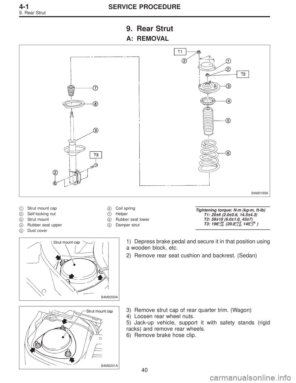
9. Rear Strut
A: REMOVAL
B4M0199A
�1Strut mount cap
�
2Self-locking nut
�
3Strut mount
�
4Rubber seat upper
�
5Dust cover�
6Coil spring
�
7Helper
�
8Rubber seat lower
�
9Damper strut
Tightening torque: N⋅m (kg-m, ft-lb)
T1: 20±6 (2.0±0.6, 14.5±4.3)
T2: 59±10 (6.0±1.0, 43±7)
T3: 196
+39
�10(20.0+4.0
�1.0, 145+29
�7)
B4M0200A
1) Depress brake pedal and secure it in that position using
a wooden block, etc.
2) Remove rear seat cushion and backrest. (Sedan)
B4M0201A
3) Remove strut cap of rear quarter trim. (Wagon)
4) Loosen rear wheel nuts.
5) Jack-up vehicle, support it with safety stands (rigid
racks) and remove rear wheels.
6) Remove brake hose clip.
40
4-1SERVICE PROCEDURE
9. Rear Strut
Page 1048 of 2890
 Permanent distortion or breakage of coil spring Replace.
(2) Unsmooth operation of damper st")
1. Suspension
1. IMPROPER VEHICLE POSTURE OR IMPROPER
WHEEL ARCH HEIGHT
Possible causes Countermeasures
(1) Permanent distortion or breakage of coil spring Replace.
(2) Unsmooth operation of damper strut Replace.
(3) Installation of wrong strut Replace with proper parts.
(4) Installation of wrong coil spring Replace with proper parts.
2. POOR RIDE COMFORT
1) Large rebound shock
2) Rocking of vehicle continues too long after running over
bump and/or hump.
3) Large shock in bumping
Possible causes Countermeasures
(1) Breakage of coil spring Replace.
(2) Over-inflation pressure of tire Adjust.
(3) Improper wheel arch height Adjust or replace coil springs with new ones.
(4) Fault in operation of damper strut Replace.
(5) Damage or deformation of strut mount Replace.
(6) Unsuitability of maximum and/or minimum length of
damper strutReplace with proper parts.
(7) Deformation or loss of bushing Replace.
(8) Deformation or damage of helper in strut assembly Replace.
(9) Oil leakage of damper strut Replace.
3. NOISE
Possible causes Countermeasures
(1) Wear or damage of damper strut component parts Replace.
(2) Loosening of suspension link installing bolt and/or nut Retighten to the specified torque.
(3) Deformation or loss of bushing Replace.
(4) Unsuitability of maximum and/or minimum length of
damper strutReplace with proper parts.
(5) Breakage of coil spring Replace.
(6) Wear or damage of ball joint Replace.
(7) Deformation of stabilizer clamp Replace.
47
4-1DIAGNOSTICS
1. Suspension
Page 1404 of 2890
11. Compressor
Compressor is a swash plate type. When trouble occurs,
replace compressor as a single unit.
B4M0090
A: COMPRESSOR CLUTCH INSPECTION
Compressor clutch trouble is often caused by clutch slip-
page and noise. Check and take corrective measures, as
required.
1) Remove belt cover.
2) Check that clearance between drive plate and pulley
over the entire perimeter is within specifications.
Clearance:
0.3 — 0.6 mm (0.012 — 0.024 in)
B4M0091
3) Check that voltage applied to magnetic coil is at least
10.5 volts.
4) When noise is noted, check that it originates in either
compressor or pulley bearing.
30
4-7SERVICE PROCEDURE
11. Compressor
Page 1615 of 2890

1. Engine Electrical
A: SPECIFICATIONS
Item Designation
StarterType Reduction type
ModelMT
TN128000-8311AT
TN128000-8321
Manufacturer NIPPONDENSO TENNESSEE
Voltage and output 12 V — 1.0 kW 12 V — 1.4 kW
Direction of rotation Counterclockwise (when observed from pinion)
Number of pinion teeth 8 9
No-load
characteristicsVoltage 11 V
Current 90 A or less
Rotating
speed3,000 rpm or more 2,900 rpm or more
Load
characteristicsVoltage 8 V
Current 280 A or less 370 A or less
Torque 9.8 N⋅m (1.0 kg-m, 7.2 ft-lb) 13.7 N⋅m (1.4 kg-m, 10.1 ft-lb)
Rotating
speed900 rpm or more 880 rpm or more
Lock
characteristicsVoltage 5 V
Current 800 A or less 1,050 A or less
Torque 27.5 N⋅m (2.8 kg-m, 20.3 ft-lb) or more
GeneratorType Rotating-field three-phase type, Voltage regulator built-in type
Model LR185-701H
Manufacturer HITACHI AUTOMOTIVE PRODUCTS
Voltage and output 12 V — 85 A
Polarity on ground side Negative
Rotating direction Clockwise (when observed from pulley side)
Armature connection 3-phase Y-type
Output current1,500 rpm — 35 A or more
2,500 rpm — 62 A or more
5,000 rpm — 82 A or more
Regulated voltage 14.5
+0.3
�0.4V [20°C (68°F)]
Ignition
coilModel F-569-01R
Manufacturer Diamond
Primary coil resistance 0.69Ω±10%
Secondary coil resistance 21.0 kΩ±15%
Insulation resistance between
primary terminal and caseMore than 10 MΩ
Spark
plugType and manufacturerRC10YC4 .......... CHAMPION
Alternate
(BKR6E-11 .......... NGK
K20PR-U11 .......... NIPPONDENSO)
Thread size mm 14, P = 1.25
Spark gap mm (in) 1.0 — 1.1 (0.039 — 0.043)
2
6-1SPECIFICATIONS AND SERVICE DATA
1. Engine Electrical
Page 1618 of 2890
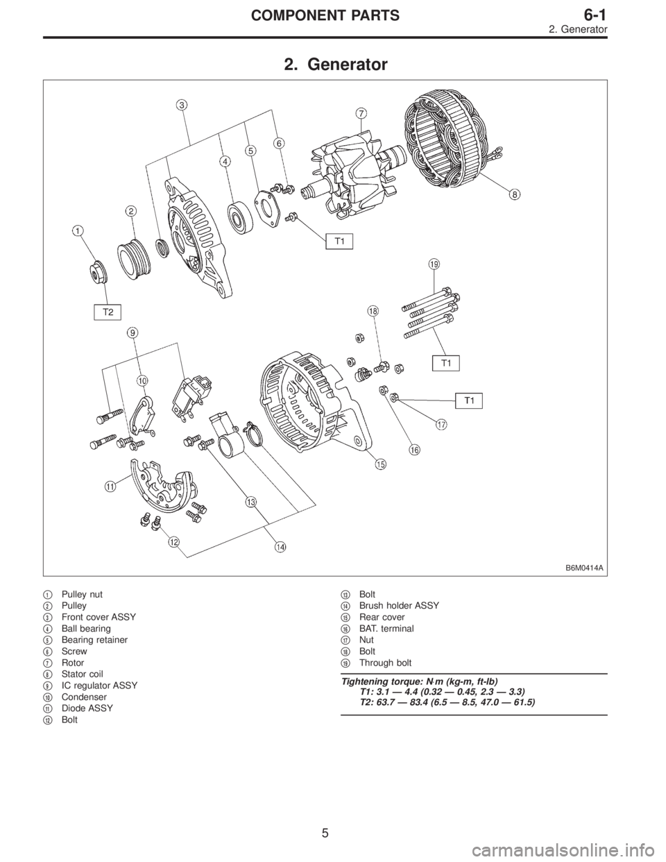
2. Generator
B6M0414A
�1Pulley nut
�
2Pulley
�
3Front cover ASSY
�
4Ball bearing
�
5Bearing retainer
�
6Screw
�
7Rotor
�
8Stator coil
�
9IC regulator ASSY
�
10Condenser
�
11Diode ASSY
�
12Bolt�
13Bolt
�
14Brush holder ASSY
�
15Rear cover
�
16BAT. terminal
�
17Nut
�
18Bolt
�
19Through bolt
Tightening torque: N⋅m (kg-m, ft-lb)
T1: 3.1 — 4.4 (0.32 — 0.45, 2.3 — 3.3)
T2: 63.7 — 83.4 (6.5 — 8.5, 47.0 — 61.5)
5
6-1COMPONENT PARTS
2. Generator