Page 632 of 2890
B2M0159
22) Remove bolts which hold intake manifold onto cylinder
heads.
B2M0160
23) Remove intake manifold.
B2M0757A
B: DISASSEMBLY
1) Disconnect engine ground terminal from intake mani-
fold.
B2M0347A
2) Disconnect connectors from throttle position sensor,
ignition coil, fuel injectors, idle air control solenoid valve,
purge control solenoid valve and EGR solenoid valve.
3) Remove engine harness from intake manifold.
�
1EGR solenoid valve
�
2Throttle position sensor
�
3Idle air control solenoid valve
�
4Purge control solenoid valve
�
5Harness band
H2M1247
4) Remove idle air control solenoid valve from intake
manifold.
12
2-7SERVICE PROCEDURE
4. Intake Manifold
Page 634 of 2890
B2M0347A
5) Install engine harness onto intake manifold.
6) Connect connectors to throttle position sensor, ignition
coil, fuel injectors, idle air control solenoid valve, purge
control solenoid valve and EGR solenoid valve.
�
1EGR solenoid valve
�
2Throttle position sensor
�
3Idle air control solenoid valve
�
4Purge control solenoid valve
�
5Harness band
B2M0757A
7) Connect engine ground terminal to intake manifold.
B2M0159
D: INSTALLATION
1) Install intake manifold onto cylinder heads.
CAUTION:
Always use new gaskets.
Tightening torque:
25±2 N⋅m (2.5±0.2 kg-m, 18.1±1.4 ft-lb)
G2M0296
2) Connect fuel hoses.
G2M0091
3) Connect connector to oil pressure switch.
14
2-7SERVICE PROCEDURE
4. Intake Manifold
Page 636 of 2890
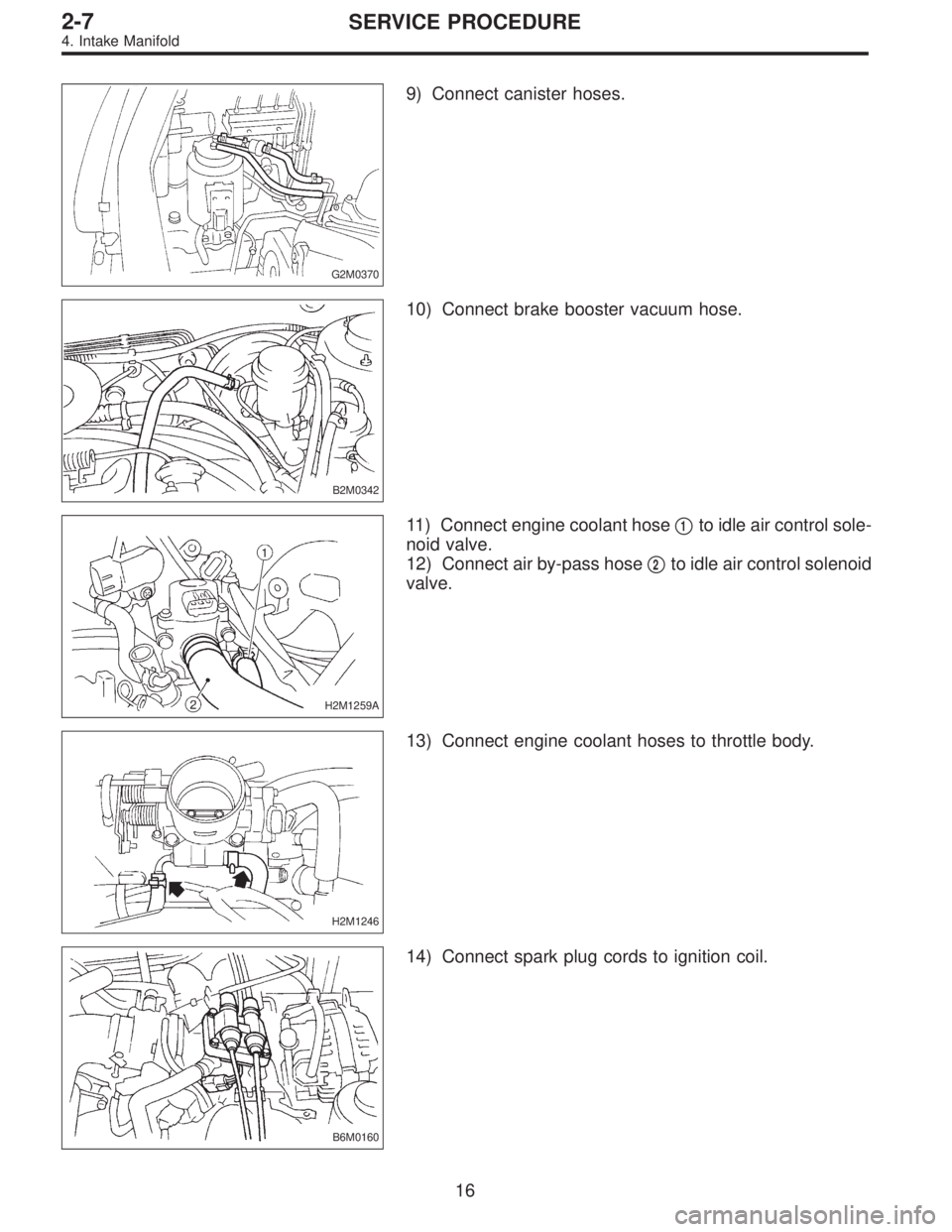
G2M0370
9) Connect canister hoses.
B2M0342
10) Connect brake booster vacuum hose.
H2M1259A
11) Connect engine coolant hose�1to idle air control sole-
noid valve.
12) Connect air by-pass hose�
2to idle air control solenoid
valve.
H2M1246
13) Connect engine coolant hoses to throttle body.
B6M0160
14) Connect spark plug cords to ignition coil.
16
2-7SERVICE PROCEDURE
4. Intake Manifold
Page 1005 of 2890

�6Rear bushing
�7Stop rubber (Front)
�8Ball joint
�9Transverse link
�10")
1. Conventional Suspension
1. FRONT SUSPENSION
B4M0765A
�1Front crossmember
�
2Bolt ASSY
�3Housing
�4Washer
�5Stop rubber (Rear)
�6Rear bushing
�7Stop rubber (Front)
�8Ball joint
�9Transverse link
�10Cotter pin
�11Front bushing
�12Stabilizer link
�13Clamp
�14Bushing (2200 cc model)
�15Stabilizer (2200 cc model)
�16Jack-up plate
�17Dust seal
�18Strut mount
�
19Spacer
�20Upper spring seat�
21Rubber seat
�22Dust cover
�23Helper
�24Coil spring
�25Damper strut
�26Adjusting bolt
�27Castle nut
�28Self-locking nut
�29Adapter front crossmember
(OUTBACK model)
�
30Clip (OUTBACK model)
�31Bushing
(2500 cc and OUTBACK model)
�
32Clamp
(2500 cc and OUTBACK model)
Tightening torque: N⋅m (kg-m, ft-lb)
T1: 18±5 (1.8±0.5, 13.0±3.6)
T2: 20±6 (2.0±0.6, 14.5±4.3)
T3: 25±4 (2.5±0.4, 18.1±2.9)
T4: 29±5 (3.0±0.5, 21.7±3.6)
T5: 39 (4, 29)
T6: 44±6 (4.5±0.6, 32.5±4.3)
T7: 49±10 (5.0±1.0, 36±7)
T8: 54±5 (5.5±0.5, 39.8±3.6)
T9: 98±15 (10.0±1.5, 72±11)
T10:152±20 (15.5±2.0, 112±14)
T11:186±10 (19.0±1.0, 137±7)
T12:245±49 (25.0±5.0, 181±36)
4
4-1COMPONENT PARTS
1. Conventional Suspension
Page 1006 of 2890

B4M0766A
�1Stabilizer
�
2Stabilizer bracket
�
3Stabilizer bushing
�
4Clamp
�
5Floating bushing
�
6Stopper
�
7Stabilizer link
�
8Rear lateral link
�
9Bushing (C)
�
10Bush")
2. REAR SUSPENSION (AWD MODEL)
B4M0766A
�1Stabilizer
�
2Stabilizer bracket
�
3Stabilizer bushing
�
4Clamp
�
5Floating bushing
�
6Stopper
�
7Stabilizer link
�
8Rear lateral link
�
9Bushing (C)
�
10Bushing (A)
�
11Front lateral link
�
12Bushing (B)
�
13Trailing link rear bushing
�
14Trailing link
�
15Trailing link front bushing�
16Trailing link bracket
�
17Cap (Protection)
�
18Washer
�
19Rear crossmember
�
20Strut mount cap
�
21Strut mount
�
22Rubber seat upper
�
23Dust cover
�
24Coil spring
�
25Helper
�
26Rubber seat lower
�
27Damper strut
�
28Self-locking nut
�
29Crossmember reinforcement
lower (Sedan model)
�
30Adapter rear crossmember
(OUTBACK model)
Tightening torque: N⋅m (kg-m, ft-lb)
T1: 20±6 (2.0±0.6, 14.5±4.3)
T2: 25±7 (2.5±0.7, 18.1±5.1)
T3: 44±6 (4.5±0.6, 32.5±4.3)
T4: 59±10 (6.0±1.0, 43±7)
T5: 98±15 (10.0±1.5, 72±11)
T6: 98±20 (10.0±2.0, 72±14)
T7: 113±15 (11.5±1.5, 83±11)
T8: 127±20 (13.0±2.0, 94±14)
T9: 137±20 (14.0±2.0, 101±14)
T10:196
+39
�10(20.0+4.0
�1.0, 145+29
�7)
5
4-1COMPONENT PARTS
1. Conventional Suspension
Page 1007 of 2890
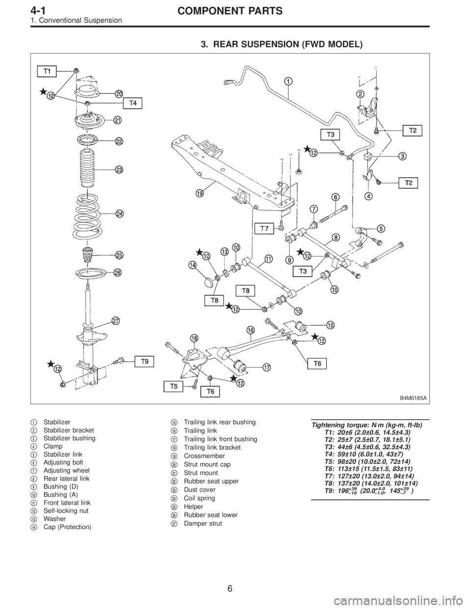
3. REAR SUSPENSION (FWD MODEL)
B4M0185A
�1Stabilizer
�
2Stabilizer bracket
�
3Stabilizer bushing
�
4Clamp
�
5Stabilizer link
�
6Adjusting bolt
�
7Adjusting wheel
�
8Rear lateral link
�
9Bushing (D)
�
10Bushing (A)
�
11Front lateral link
�
12Self-locking nut
�
13Washer
�
14Cap (Protection)�
15Trailing link rear bushing
�
16Trailing link
�
17Trailing link front bushing
�
18Trailing link bracket
�
19Crossmember
�
20Strut mount cap
�
21Strut mount
�
22Rubber seat upper
�
23Dust cover
�
24Coil spring
�
25Helper
�
26Rubber seat lower
�
27Damper strut
Tightening torque: N⋅m (kg-m, ft-lb)
T1: 20±6 (2.0±0.6, 14.5±4.3)
T2: 25±7 (2.5±0.7, 18.1±5.1)
T3: 44±6 (4.5±0.6, 32.5±4.3)
T4: 59±10 (6.0±1.0, 43±7)
T5: 98±20 (10.0±2.0, 72±14)
T6: 113±15 (11.5±1.5, 83±11)
T7: 127±20 (13.0±2.0, 94±14)
T8: 137±20 (14.0±2.0, 101±14)
T9: 196
+39
�10(20.0+4.0
�1.0, 145+29
�7)
6
4-1COMPONENT PARTS
1. Conventional Suspension
Page 1022 of 2890
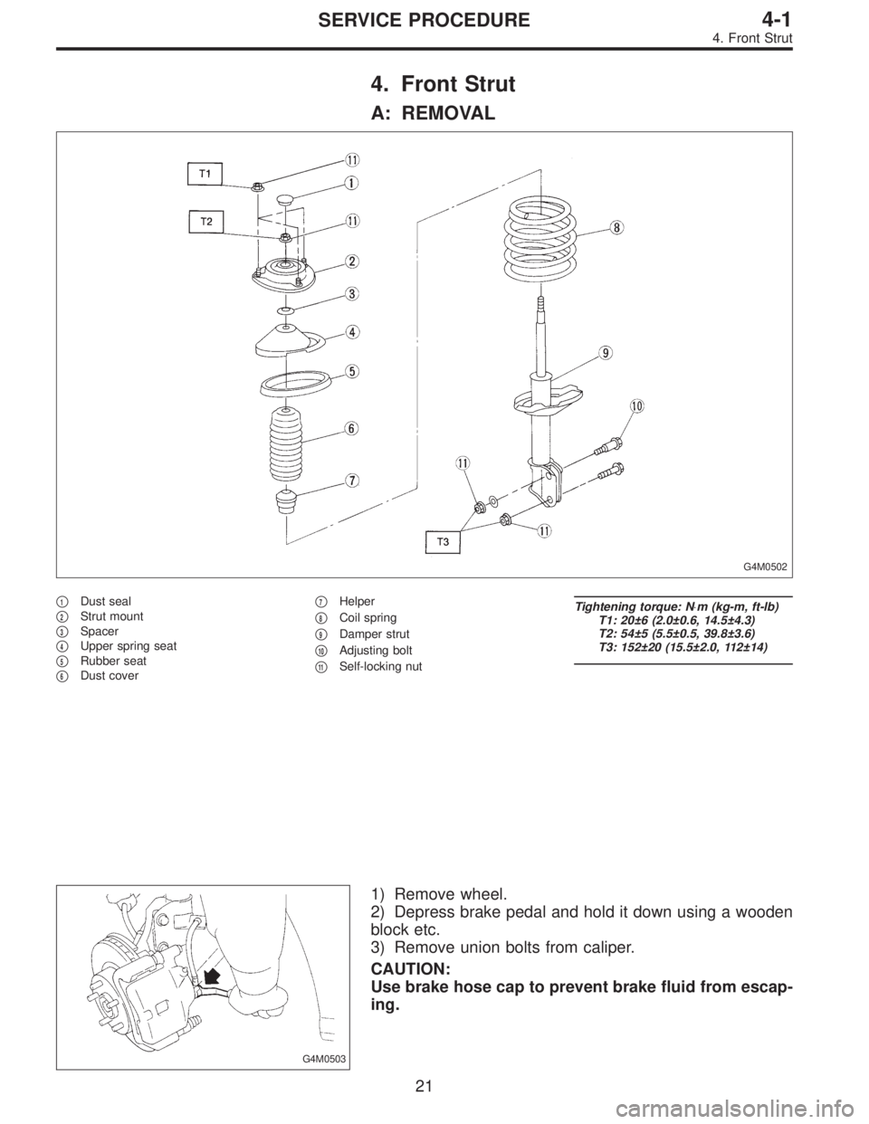
4. Front Strut
A: REMOVAL
G4M0502
�1Dust seal
�
2Strut mount
�
3Spacer
�
4Upper spring seat
�
5Rubber seat
�
6Dust cover�
7Helper
�
8Coil spring
�
9Damper strut
�
10Adjusting bolt
�
11Self-locking nut
Tightening torque: N⋅m (kg-m, ft-lb)
T1: 20±6 (2.0±0.6, 14.5±4.3)
T2: 54±5 (5.5±0.5, 39.8±3.6)
T3: 152±20 (15.5±2.0, 112±14)
G4M0503
1) Remove wheel.
2) Depress brake pedal and hold it down using a wooden
block etc.
3) Remove union bolts from caliper.
CAUTION:
Use brake hose cap to prevent brake fluid from escap-
ing.
21
4-1SERVICE PROCEDURE
4. Front Strut
Page 1023 of 2890
G4M0504
4) Remove brake hose clamp and disconnect brake hose
from strut. Attach brake hose to body using gum tape.
5) Scribe an alignment mark on the camber adjusting bolt
which secures strut to housing.
6) Remove bolt securing the A.B.S. sensor harness.
(A.B.S. equipped models.)
G4M0505
7) Remove two bolts securing housing to strut.
CAUTION:
While holding head of adjusting bolt, loosen self-lock-
ing nut.
8) Remove the three nuts securing strut mount to body.
G4M0506
B: DISASSEMBLY
1) Using a coil spring compressor, compress coil spring.
G4M0507
2) Using ST, remove self-locking nut.
ST 927760000 STRUT MOUNT SOCKET
3) Remove strut mount, upper spring seat and rubber seat
from strut.
4) Gradually decreasing compression force of spring
compressor, and remove coil spring.
5) Remove dust cover and helper.
22
4-1SERVICE PROCEDURE
4. Front Strut
 Remove bolts which hold intake manifold onto cylinder
heads.
B2M0160
23) Remove intake manifold.
B2M0757A
B: DISASSEMBLY
1) Disconnect engine ground terminal from intake mani-
fold.
B2M034")
 Install engine harness onto intake manifold.
6) Connect connectors to throttle position sensor, ignition
coil, fuel injectors, idle air control solenoid valve, purge
control solenoid valve")
 Remove brake hose clamp and disconnect brake hose
from strut. Attach brake hose to body using gum tape.
5) Scribe an alignment mark on the camber adjusting bolt
which secures strut to housi")