Page 1777 of 2890

�
2Ignition coil
�
3Ignitor
�
4Crankshaft position sensor
�
5Camshaft position sensor
�
6Throttle position sensor
�
7Fuel injectors
�
8Pressure regulator
�
9Engine coolan")
�1Engine control module (ECM)
�
2Ignition coil
�
3Ignitor
�
4Crankshaft position sensor
�
5Camshaft position sensor
�
6Throttle position sensor
�
7Fuel injectors
�
8Pressure regulator
�
9Engine coolant temperature sensor
�
10Mass air flow sensor
�
11Idle air control solenoid valve
�
12Purge control solenoid valve
�
13Fuel pump
�
14PCV valve
�
15Air cleaner
�
16Canister
�
17Main relay
�
18Fuel pump relay
�
19Fuel filter
�
20Front catalytic converter
�
21Rear catalytic converter
�
22EGR valve�
23EGR control solenoid valve
�
24Radiator fan
�
25Radiator fan relay
�
26Pressure sources switching solenoid valve
�
27Knock sensor
�
28Back-pressure transducer
�
29Front oxygen sensor
�
30Rear oxygen sensor
�
31Pressure sensor
�
32A/C compressor
�
33Inhibitor switch
�
34CHECK ENGINE malfunction indicator lamp (MIL)
�
35Tachometer
�
36A/C relay
�
37A/C control module
�
38Ignition switch
�
39Transmission control module (TCM)
�
40Vehicle speed sensor
�
41Data link connector (Subaru select monitor)
�
42Data link connector (OBD-II general scan tool)
�
43Two way valve
�
44Filter
9
2-7ON-BOARD DIAGNOSTICS II SYSTEM
1. General
Page 1779 of 2890

�
2Ignition coil
�
3Ignitor
�
4Crankshaft position sensor
�
5Camshaft position sensor
�
6Throttle position sensor
�
7Fuel injectors
�
8Pressure regulator
�
9Engine coolan")
�1Engine control module (ECM)
�
2Ignition coil
�
3Ignitor
�
4Crankshaft position sensor
�
5Camshaft position sensor
�
6Throttle position sensor
�
7Fuel injectors
�
8Pressure regulator
�
9Engine coolant temperature sensor
�
10Mass air flow sensor
�
11Idle air control solenoid valve
�
12Purge control solenoid valve
�
13Fuel pump
�
14PCV valve
�
15Air cleaner
�
16Canister
�
17Main relay
�
18Fuel pump relay
�
19Fuel filter
�
20Front catalytic converter
�
21Rear catalytic converter
�
22EGR valve
�
23EGR control solenoid valve�
24Radiator fan
�
25Radiator fan relay
�
26Pressure sources switching solenoid valve
�
27Knock sensor
�
28Back-pressure transducer
�
29Front oxygen sensor
�
30Rear oxygen sensor (Except California model)
�
31Pressure sensor
�
32A/C compressor
�
33Inhibitor switch
�
34CHECK ENGINE malfunction indicator lamp (MIL)
�
35Tachometer
�
36A/C relay
�
37A/C control module
�
38Ignition switch
�
39Transmission control module (TCM)
�
40Vehicle speed sensor 2
�
41Data link connector (For Subaru select monitor)
�
42Data link connector (For Subaru select monitor and OBD-II
general scan tool)
�
43Two way valve
�
44Rear oxygen sensor (California model only)
�
45Filter
11
2-7ON-BOARD DIAGNOSTICS II SYSTEM
1. General
Page 1788 of 2890
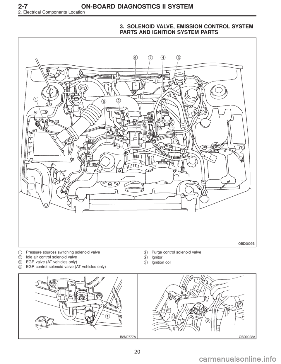
3. SOLENOID VALVE, EMISSION CONTROL SYSTEM
PARTS AND IGNITION SYSTEM PARTS
OBD0009B
�1Pressure sources switching solenoid valve
�
2Idle air control solenoid valve
�
3EGR valve (AT vehicles only)
�
4EGR control solenoid valve (AT vehicles only)�
5Purge control solenoid valve
�
6Ignitor
�
7Ignition coil
B2M0777AOBD0022A
20
2-7ON-BOARD DIAGNOSTICS II SYSTEM
2. Electrical Components Location
Page 1867 of 2890
D: IGNITION CONTROL SYSTEM
8D1Check ignition system for sparks.
8D2Check power supply circuit for ignition coil.
8D3Check ignition coil.
8D4Check harness between ignitor and ignition
coil connector.
8D5Check input signal for ignitor.
8D6Check harness of ignitor ground circuit.
8D7Check harness between ECM and ignitor
connector.
CAUTION:
After repair or replacement of faulty parts, conduct
CLEAR MEMORY and INSPECTION MODES.
WIRING DIAGRAM:
B2M0522
�
�
�
�
�
�
99
2-7ON-BOARD DIAGNOSTICS II SYSTEM
8. Diagnostics for Engine Starting Failure
Page 1868 of 2890
 Remove plug cord cap from each spark plug.
2) Install new spark plug on plug cord cap.
CAUTION:
Do not remove spark plug from engine.
3) Cont")
OBD0727A
B2M0644A
8D1
CHECK IGNITION SYSTEM FOR SPARKS.
1) Remove plug cord cap from each spark plug.
2) Install new spark plug on plug cord cap.
CAUTION:
Do not remove spark plug from engine.
3) Contact spark plug’s thread portion on engine.
4) While opening throttle valve fully, crank engine to check
that spark occurs at each cylinder.
: Does spark occur at each cylinder?
: Check fuel pump system.
: Go to step8D2.
OBD0123A
8D2CHECK POWER SUPPLY CIRCUIT FOR
IGNITION COIL.
1) Turn ignition switch to OFF.
2) Disconnect connector from ignition coil.
3) Turn ignition switch to ON.
4) Measure power supply voltage between ignition coil
connector and engine ground.
: Connector & terminal
(E12) No. 2 (+)—Engine ground (�):
Is the voltage more than 10 V?
: Go to step8D3.
: Repair harness between ignition coil and ignition
switch connector.
OBD0124
8D3
CHECK IGNITION COIL.
1) Measure resistance between ignition coil terminals to
check primary coil.
: Terminals
No. 2—No. 1:
Is the resistance between 0.4 and 1.0Ω?
: Go to next.
: Replace ignition coil.
100
2-7ON-BOARD DIAGNOSTICS II SYSTEM
8. Diagnostics for Engine Starting Failure
Page 1869 of 2890
: Terminals
No. 2—No. 3:
Is the resistance between 0.4 and 1.0Ω?
: Replace ignition coil.
: Go to next step 2).
OBD0125A
2) Measure resistance between spark plug cord contact
portions to check secondary coil.
: Terminals
#1—#2:
Is the resistance between 18 and 24Ω?
: Go to next.
: Replace ignition coil.
: Terminals
#3—#4:
Is the resistance between 18 and 24Ω?
: Go to step8D4.
: Replace ignition coil.
OBD0126A
8D4CHECK HARNESS BETWEEN IGNITOR
AND IGNITION COIL CONNECTOR.
1) Turn ignition switch to OFF.
2) Disconnect connector from ignitor.
3) Measure resistance of harness connector between igni-
tion coil and ignitor.
: Connector & terminal
(B13) No. 5—(E12) No. 1:
Is the resistance less than 1Ω?
: Go to next.
: Go to next.
: Connector & terminal
(B13) No. 6—(E12) No. 3:
Is the resistance less than 1Ω?
: Go to step8D5.
: Go to next.
101
2-7ON-BOARD DIAGNOSTICS II SYSTEM
8. Diagnostics for Engine Starting Failure
Page 1870 of 2890
?
: Repair poor contact in coupling connector.
: Repair harness between ignition coil and ignitor
connector.
OBD0728
B2M0224A
8D5
CHECK INPUT SIGNAL")
: Is there poor contact in coupling connector
(B22)?
: Repair poor contact in coupling connector.
: Repair harness between ignition coil and ignitor
connector.
OBD0728
B2M0224A
8D5
CHECK INPUT SIGNAL FOR IGNITOR.
Check if voltage varies synchronously with engine speed
when cranking, while monitoring voltage between ignitor
connector and engine ground.
: Connector & terminal:
(B13) No. 1 (+)—Engine ground (�):
Is the voltage more than 10 V?
: Go to next.
: Replace ignitor.
: Connector & terminal:
(B13) No. 2 (+)—Engine ground (�):
Is the voltage more than 10 V?
: Go to step8D6.
: Replace ignitor.
OBD0128A
8D6CHECK HARNESS OF IGNITOR GROUND
CIRCUIT.
1) Turn ignition switch to OFF.
2) Measure resistance between ignitor and engine ground.
: Connector & terminal
(B13) No. 3—Engine ground:
Is the resistance less than 5Ω?
: Go to step8D7.
: Repair harness between ignitor connector and
engine grounding terminal.
102
2-7ON-BOARD DIAGNOSTICS II SYSTEM
8. Diagnostics for Engine Starting Failure
Page 1886 of 2890

Throttle position sensor
Crankshaft position sensor & Camshaft po")
9. General Diagnostics Table
1. FOR ENGINE
12345678910111213
Problem parts
Mass air flow sensor
Engine coolant temperature sensor (*1)
Throttle position sensor
Crankshaft position sensor & Camshaft position sensor (*2)
Idle air control solenoid valve
Knock sensor
Purge control solenoid valve
EGR valve
Fuel injection parts (*3)
Ignition parts (*4)
Fuel pump and relay
A/C switch and A/C cut relay
Engine torque control signal circuitSymptom
1 Engine stalls during idling.�� � � ���
2 Rough idling�� � � � �
3 Engine does not return to idle.���
4 Poor acceleration�� � � ���
5Engine stalls or engine sags or hesi-
tates at acceleration.�� � � ��� �
6 Surge�� � �� �
7 Spark knock����
8 After burning in exhaust system�� � �
*1: The mark,�, indicates the symptom occurring only in cold temperatures.
*2: For items with the mark,�, ensure the secure installation of crankshaft position sensor and camshaft position sensor. Replacement is
not necessary.
*3: Check fuel injector, fuel pressure regulator and fuel filter.
*4: Check ignitor, ignition coil and spark plug.
NOTE:
Malfunction of parts other than the above is also possible. Refer to 1. Engine Trouble in General [K100] in Repair Section 2-3 or 2-3b of
the Service Manual.
11 8
2-7ON-BOARD DIAGNOSTICS II SYSTEM
9. General Diagnostics Table

.
OBD0125A
2) Measure resistance between spark plug cord contact
portions to check sec")