Page 1624 of 2890
B6M0431A
11) Take out steel ball from clutch.
CAUTION:
Be careful not to lose steel ball.
B6M0432A
12) Remove idle gear from housing.
B6M0433A
13) Remove retainer and roller from housing.
CAUTION:
Be careful not to drop retainer and roller.
B6M0434A
14) Remove coil spring from magnetic switch.
D: INSPECTION
1. ARMATURE
1) Check commutator for any sign of burns of rough sur-
faces or stepped wear. If wear is of a minor nature, correct
it by using sand paper.
11
6-1SERVICE PROCEDURE
1. Starter
Page 1627 of 2890
B6M0439A
5. BEARING
1) Rotate bearing by hand; no binding should exist.
2) Rotate bearing rapidly; no abnormal noise should be
heard.
E: ASSEMBLY
Assembly is in the reverse order of disassembly proce-
dures. Observe the following:
1) Before assembling, lubricate disassembled parts at the
points shown in“COMPONENT PARTS 6-1 [C101] and 6-1
[C102]”.
Grease:
ESSO BEACON 325
SCHELL ALVANIA GREASE RA or equivalent
B6M0470A
2) Assembling magnetic switch, clutch, and housing
To assemble, first install clutch to magnetic switch, then
install idle gear, and finally install clutch.
CAUTION:
�Do not forget to install steel ball and coil spring to
clutch.
�Attach bearing to idle gear beforehand.
B6M0427A
3) Installing armature to yoke
CAUTION:
Do not forget to put felt washer on armature shaft bear-
ing.
B6M0471A
4) Installing brushes
Assemble brush holder to yoke as shown, then assemble
two yoke-side brushes to brush holder.
14
6-1SERVICE PROCEDURE
1. Starter
Page 1631 of 2890
B6M0477A
CAUTION:
When holding rotor with vise, insert aluminum plates
or wood pieces on the contact surfaces of the vise to
prevent rotor from damage.
B6M0478A
4) Remove rotor from front cover.
5) Remove three screws from front cover and then bear-
ing retainer and ball bearing.
B6M0479A
6) Remove bolt which secure battery terminal bolt, and
remove rear cover. Remove nuts which secure diode plate,
and remove stator and rear cover.
B6M0480A
7) Separate diode plate from stator coil.
(1) Cut the connecting position�
Aof stator coil to
diode.
(2) Unsolder connection�
Band throughout the lead
wire of stator coil.
B6M0481
(3) Remove stator coil from diode plate.
17
6-1SERVICE PROCEDURE
2. Generator
Page 1633 of 2890
B6M0486
5) Ball bearing
Check rear ball bearing. Replace it if it is noisy or if rotor
does not turn smoothly.
G6M0078
2. STATOR
1) Continuity test
Inspect stator coil for continuity between its terminals.
When there is no continuity between individual terminals,
cable is broken.
Replace stator coil.
G6M0079
2) Insulation test
Inspect stator coil for continuity between stator core and
each terminal. If there is continuity, replace stator coil.
B6M0487A
3. BRUSH
Measure brush length. If brush is worn, replace brush
holder assembly.
Brush length (�):
Standard
20.5 mm (0.807 in)
Limit
1.5 mm (0.059 in)
B6M0488A
4. DIODE ASSEMBLY
The diode consists of eight diodes, four each being located
on the positive and negative sides. The diode is necessary
to restrict current flow to one direction.
Check all diodes, for continuity. If any diode is faulty,
replace diode assembly.
19
6-1SERVICE PROCEDURE
2. Generator
Page 1635 of 2890
2) Check operation as shown in chart below.
No.Switch operation
Value of
voltage meterLamp operation
Remarks
123 12
1 ON OFF OFF 12 V DIM ONCheck initial
excitation.
2 ON ON OFF 12 VON
or
BLINKOFF Check total excitation.
3 ON ON OFF 16 VOFF
or
DIM-BLINKOFFWhen value of voltage
meter is between 12
V and 16 V.
4 OFF ON OFF 12 VON
or
BLINKONCheck connection for
S and B terminals.
5 OFF ON ON 18 V ON ONCheck for over
loading of voltage.
G6M0077
D: ASSEMBLY
Assembly is in the reverse order of disassembly proce-
dures.
CAUTION:
�When disassembling generator, replace rear ball
bearing.
�When soldering starter coil to diode, do not touch
lead wire with solder for more than 5 seconds.
B6M0492
�Before installing rear cover, insert pin from outside
of rear cover so that holds brush. After installing rear
cover, remove pin.
B6M0476A
�When installing rear cover, heat portion�Ato 50°C
(122°F) with heater drier.
21
6-1SERVICE PROCEDURE
2. Generator
Page 1648 of 2890

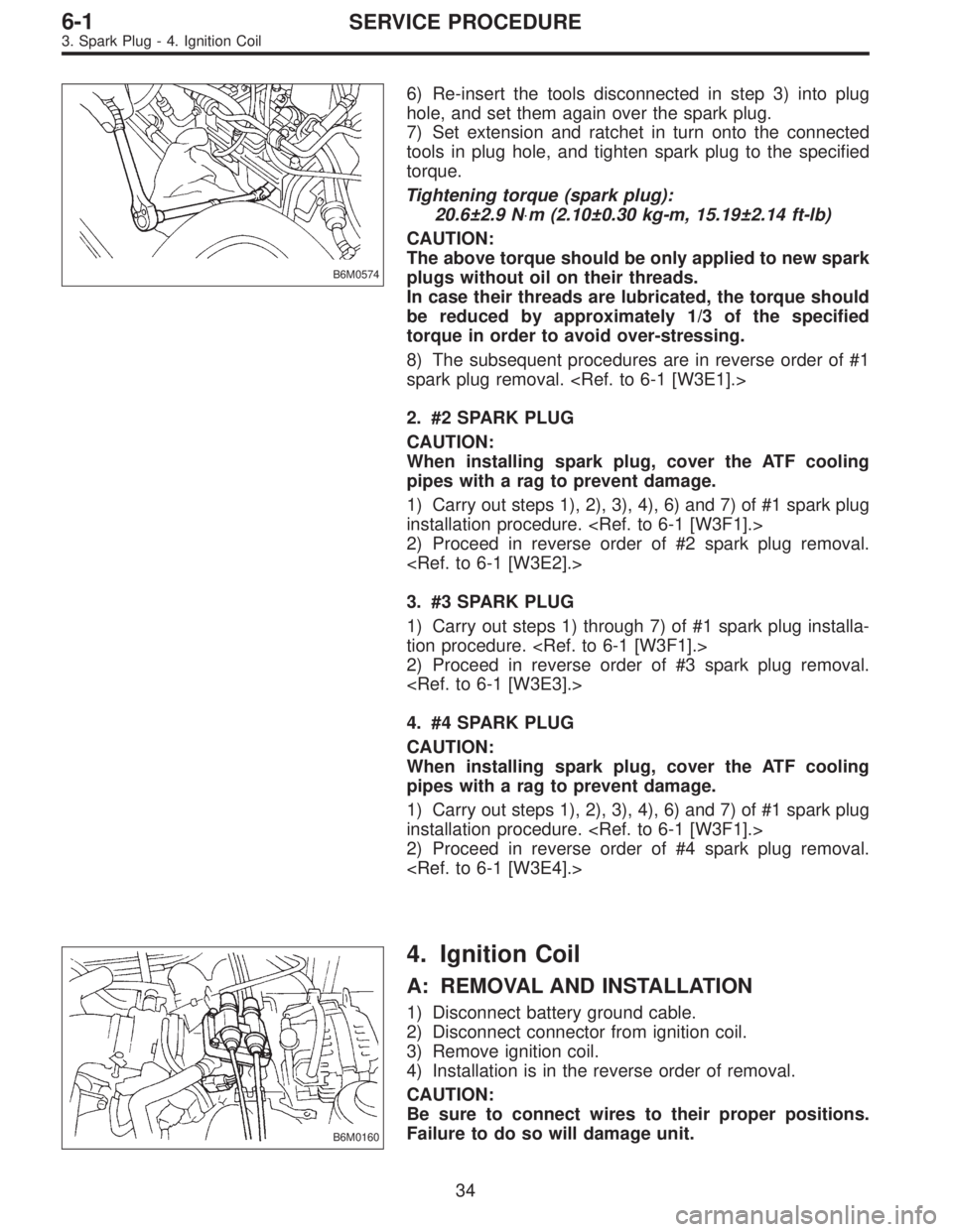
B6M0574
6) Re-insert the tools disconnected in step 3) into plug
hole, and set them again over the spark plug.
7) Set extension and ratchet in turn onto the connected
tools in plug hole, and tighten spark plug to the specified
torque.
Tightening torque (spark plug):
20.6±2.9 N⋅m (2.10±0.30 kg-m, 15.19±2.14 ft-lb)
CAUTION:
The above torque should be only applied to new spark
plugs without oil on their threads.
In case their threads are lubricated, the torque should
be reduced by approximately 1/3 of the specified
torque in order to avoid over-stressing.
8) The subsequent procedures are in reverse order of #1
spark plug removal.
2. #2 SPARK PLUG
CAUTION:
When installing spark plug, cover the ATF cooling
pipes with a rag to prevent damage.
1) Carry out steps 1), 2), 3), 4), 6) and 7) of #1 spark plug
installation procedure.
2) Proceed in reverse order of #2 spark plug removal.
3. #3 SPARK PLUG
1) Carry out steps 1) through 7) of #1 spark plug installa-
tion procedure.
2) Proceed in reverse order of #3 spark plug removal.
4. #4 SPARK PLUG
CAUTION:
When installing spark plug, cover the ATF cooling
pipes with a rag to prevent damage.
1) Carry out steps 1), 2), 3), 4), 6) and 7) of #1 spark plug
installation procedure.
2) Proceed in reverse order of #4 spark plug removal.
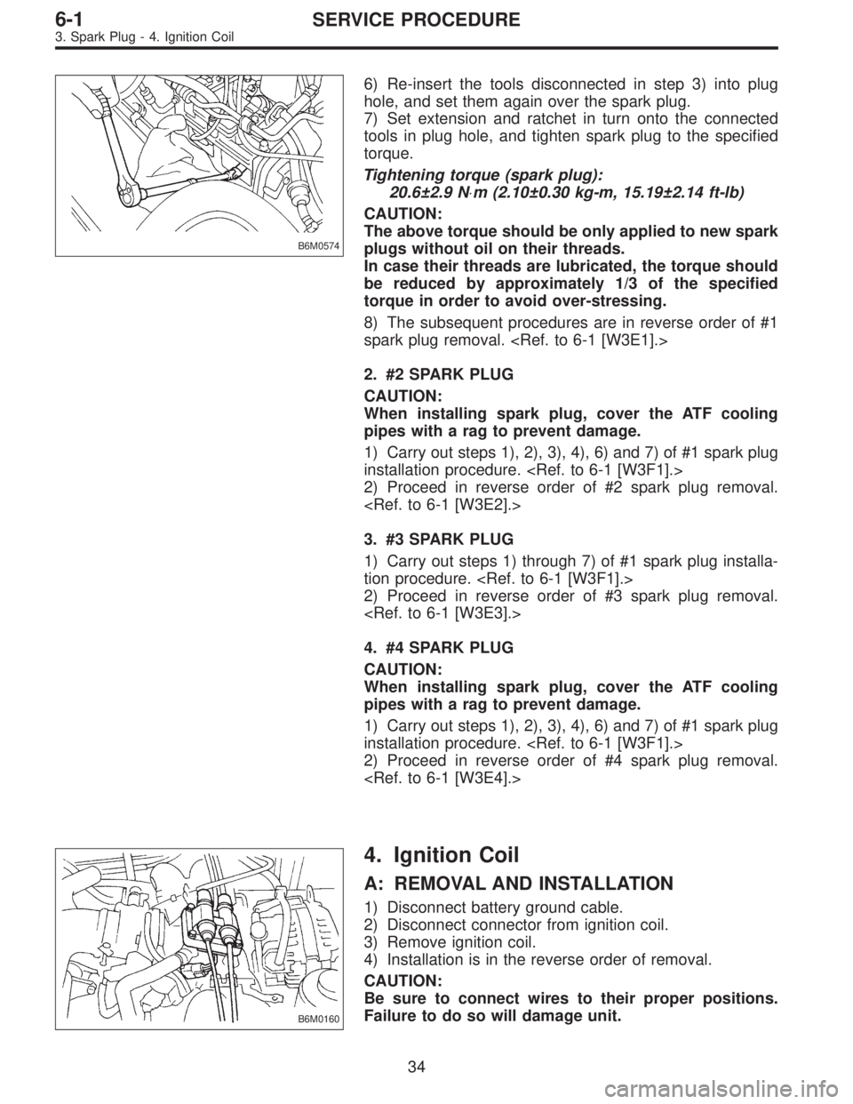
B6M0160
4. Ignition Coil
A: REMOVAL AND INSTALLATION
1) Disconnect battery ground cable.
2) Disconnect connector from ignition coil.
3) Remove ignition coil.
4) Installation is in the reverse order of removal.
CAUTION:
Be sure to connect wires to their proper positions.
Failure to do so will damage unit.
34
6-1SERVICE PROCEDURE
3. Spark Plug - 4. Ignition Coil
Page 1649 of 2890

B6M0574
6) Re-insert the tools disconnected in step 3) into plug
hole, and set them again over the spark plug.
7) Set extension and ratchet in turn onto the connected
tools in plug hole, and tighten spark plug to the specified
torque.
Tightening torque (spark plug):
20.6±2.9 N⋅m (2.10±0.30 kg-m, 15.19±2.14 ft-lb)
CAUTION:
The above torque should be only applied to new spark
plugs without oil on their threads.
In case their threads are lubricated, the torque should
be reduced by approximately 1/3 of the specified
torque in order to avoid over-stressing.
8) The subsequent procedures are in reverse order of #1
spark plug removal.
2. #2 SPARK PLUG
CAUTION:
When installing spark plug, cover the ATF cooling
pipes with a rag to prevent damage.
1) Carry out steps 1), 2), 3), 4), 6) and 7) of #1 spark plug
installation procedure.
2) Proceed in reverse order of #2 spark plug removal.
3. #3 SPARK PLUG
1) Carry out steps 1) through 7) of #1 spark plug installa-
tion procedure.
2) Proceed in reverse order of #3 spark plug removal.
4. #4 SPARK PLUG
CAUTION:
When installing spark plug, cover the ATF cooling
pipes with a rag to prevent damage.
1) Carry out steps 1), 2), 3), 4), 6) and 7) of #1 spark plug
installation procedure.
2) Proceed in reverse order of #4 spark plug removal.
B6M0160
4. Ignition Coil
A: REMOVAL AND INSTALLATION
1) Disconnect battery ground cable.
2) Disconnect connector from ignition coil.
3) Remove ignition coil.
4) Installation is in the reverse order of removal.
CAUTION:
Be sure to connect wires to their proper positions.
Failure to do so will damage unit.
34
6-1SERVICE PROCEDURE
3. Spark Plug - 4. Ignition Coil
Page 1650 of 2890
G6M0093
B: INSPECTION
Using accurate tester, inspect the following items, and
replace if defective.
1) Primary resistance
2) Secondary coil resistance
CAUTION:
If the resistance is extremely low, this indicates the
presence of a short-circuit.
Specified resistance:
[Primary side]
Between�
1and�2
Between�3and�4
0.69Ω±10%
[Secondary side]
Between terminal No. 1 and No. 2
Between terminal No. 2 and No. 3
21.0 kΩ±15%
3) Insulation between primary terminal and case: 10 MΩ
or more.
G6M0094
5. Spark Plug Cord
A: INSPECTION
Check for:
1) Damage to cords, deformation, burning or rust forma-
tion of terminals
2) Resistance values of cords
Resistance value:
5.12—12.34 kΩ
G6M0095
6. Ignitor
A: REMOVAL AND INSTALLATION
1) Disconnect battery ground cable.
B6M0161
2) Disconnect connector from ignitor.
3) Remove screws which hold ignitor onto body.
4) Installation is in the reverse order of removal.
35
6-1SERVICE PROCEDURE
4. Ignition Coil - 6. Ignitor