Page 418 of 2890
3. Camshaft
A: REMOVAL
1. RELATED PARTS
Remove timing belt, camshaft sprockets and related parts.
2. CAMSHAFT LH
G2M0743
1) Remove camshaft position sensor.
2) Remove ignition coils.
3) Remove rocker cover and gasket.
G2M0744
4) Loosen intake camshaft cap bolts equally, a little at a
time in the numerical sequence shown in figure.
5) Remove camshaft caps and intake camshaft.
30
2-3bSERVICE PROCEDURE
3. Camshaft
Page 422 of 2890
G2M0755
4) Rocker cover installation
(1) Install gasket on rocker cover.
Install peripheral gasket and ignition coil gasket.
(2) Apply fluid packing to four front open edges of
peripheral gasket.
Fluid packing:
THREE BOND 1215 or equivalent
(3) Install rocker cover on cylinder head. Ensure gas-
ket is properly positioned during installation.
5) Install ignition coil.
6) Install cam angle sensor.
7) Similarly, install parts on right-hand side.
2. RELATED PARTS
Install timing belt, camshaft sprockets and related parts.
34
2-3bSERVICE PROCEDURE
3. Camshaft
Page 430 of 2890
D: ASSEMBLY
G2M0768
G2M0759
1) Installation of valve spring and valve
(1) Coat stem of each valve with engine oil and insert
valve into valve guide.
CAUTION:
When inserting valve into valve guide, use special care
not to damage the oil seal lip.
(2) Set cylinder head on ST1.
(3) Install valve spring and retainer using ST2.
ST1 498267600 CYLINDER HEAD TABLE
ST2 499718000 VALVE SPRING REMOVER
CAUTION:
Be sure to install the valve springs with their close-
coiled end facing the seat on the cylinder head.
(4) Compress valve spring and fit valve spring retainer
key.
(5) After installing, tap valve spring retainers lightly
with wooden hammer for better seating.
2) Install hydraulic lash adjuster.
42
2-3bSERVICE PROCEDURE
4. Cylinder Head
Page 527 of 2890
B2M0334
(3) Remove bolts which install power steering pump
from bracket.
B2M0029
(4) Place power steering pump on the right side wheel
apron.
B6M0160
8) Disconnect spark plug cords from ignition coil.
H2M1246
9) Disconnect engine coolant hoses from throttle body.
H2M1259A
10) Disconnect engine coolant hose�1from idle air con-
trol solenoid valve.
11) Disconnect air by-pass hose�
2from idle air control
solenoid valve.
9
2-7SERVICE PROCEDURE
4. Intake Manifold
Page 530 of 2890
B2M0159
22) Remove bolts which hold intake manifold onto cylinder
heads.
B2M0160
23) Remove intake manifold.
B2M0757A
B: DISASSEMBLY
1) Disconnect engine ground terminal from intake mani-
fold.
B2M0347A
2) Disconnect connectors from throttle position sensor,
ignition coil, fuel injectors, idle air control solenoid valve,
purge control solenoid valve and EGR solenoid valve.
3) Remove engine harness from intake manifold.
�
1EGR solenoid valve
�
2Throttle position sensor
�
3Idle air control solenoid valve
�
4Purge control solenoid valve
�
5Harness band
H2M1247
4) Remove idle air control solenoid valve from intake
manifold.
12
2-7SERVICE PROCEDURE
4. Intake Manifold
Page 532 of 2890
B2M0347A
5) Install engine harness onto intake manifold.
6) Connect connectors to throttle position sensor, ignition
coil, fuel injectors, idle air control solenoid valve, purge
control solenoid valve and EGR solenoid valve.
�
1EGR solenoid valve
�
2Throttle position sensor
�
3Idle air control solenoid valve
�
4Purge control solenoid valve
�
5Harness band
B2M0757A
7) Connect engine ground terminal to intake manifold.
B2M0159
D: INSTALLATION
1) Install intake manifold onto cylinder heads.
CAUTION:
Always use new gaskets.
Tightening torque:
25±2 N⋅m (2.5±0.2 kg-m, 18.1±1.4 ft-lb)
G2M0296
2) Connect fuel hoses.
G2M0091
3) Connect connector to oil pressure switch.
14
2-7SERVICE PROCEDURE
4. Intake Manifold
Page 534 of 2890
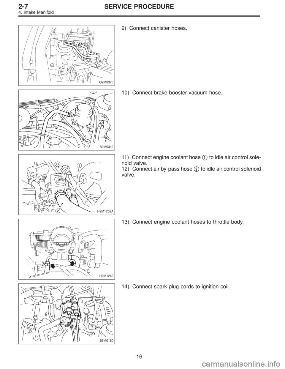
G2M0370
9) Connect canister hoses.
B2M0342
10) Connect brake booster vacuum hose.
H2M1259A
11) Connect engine coolant hose�1to idle air control sole-
noid valve.
12) Connect air by-pass hose�
2to idle air control solenoid
valve.
H2M1246
13) Connect engine coolant hoses to throttle body.
B6M0160
14) Connect spark plug cords to ignition coil.
16
2-7SERVICE PROCEDURE
4. Intake Manifold
Page 629 of 2890
B2M0334
(3) Remove bolts which install power steering pump
from bracket.
B2M0029
(4) Place power steering pump on the right side wheel
apron.
B6M0160
8) Disconnect spark plug cords from ignition coil.
H2M1246
9) Disconnect engine coolant hoses from throttle body.
H2M1259A
10) Disconnect engine coolant hose�1from idle air con-
trol solenoid valve.
11) Disconnect air by-pass hose�
2from idle air control
solenoid valve.
9
2-7SERVICE PROCEDURE
4. Intake Manifold
![SUBARU LEGACY 1996 Service Repair Manual 3. Camshaft
A: REMOVAL
1. RELATED PARTS
Remove timing belt, camshaft sprockets and related parts.
<Ref. to 2-3b [W2A0].>
2. CAMSHAFT LH
G2M0743
1) Remove camshaft position sensor.
2) Remove ignition c](/manual-img/17/57433/w960_57433-417.png "SUBARU LEGACY 1996 Service Repair Manual 3. Camshaft
A: REMOVAL
1. RELATED PARTS
Remove timing belt, camshaft sprockets and related parts.
<Ref. to 2-3b [W2A0].>
2. CAMSHAFT LH
G2M0743
1) Remove camshaft position sensor.
2) Remove ignition c")
 Rocker cover installation
(1) Install gasket on rocker cover.
Install peripheral gasket and ignition coil gasket.
(2) Apply fluid packing to four front open edges of
peripheral gasket.
Flui")
 Installation of valve spring and valve
(1) Coat stem of each valve with engine oil and insert
valve into valve guide.
CAUTION:
When inserting valve into valve guide, use")
 Remove bolts which install power steering pump
from bracket.
B2M0029
(4) Place power steering pump on the right side wheel
apron.
B6M0160
8) Disconnect spark plug cords from ignition coil.")
 Remove bolts which hold intake manifold onto cylinder
heads.
B2M0160
23) Remove intake manifold.
B2M0757A
B: DISASSEMBLY
1) Disconnect engine ground terminal from intake mani-
fold.
B2M034")
 Install engine harness onto intake manifold.
6) Connect connectors to throttle position sensor, ignition
coil, fuel injectors, idle air control solenoid valve, purge
control solenoid valve")
 Remove bolts which install power steering pump
from bracket.
B2M0029
(4) Place power steering pump on the right side wheel
apron.
B6M0160
8) Disconnect spark plug cords from ignition coil.")