Page 1552 of 2890

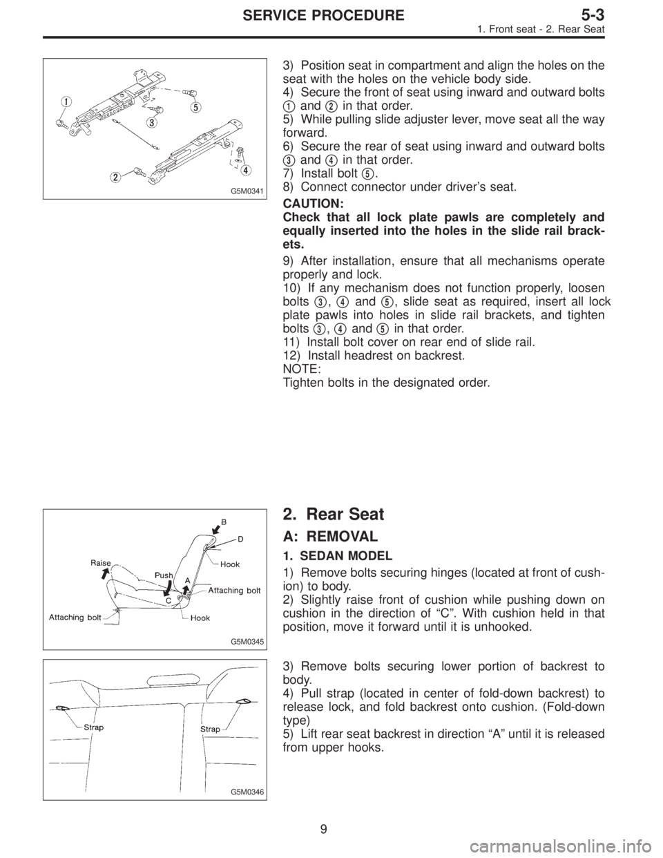
G5M0341
3) Position seat in compartment and align the holes on the
seat with the holes on the vehicle body side.
4) Secure the front of seat using inward and outward bolts
�
1and�2in that order.
5) While pulling slide adjuster lever, move seat all the way
forward.
6) Secure the rear of seat using inward and outward bolts
�
3and�4in that order.
7) Install bolt�
5.
8) Connect connector under driver’s seat.
CAUTION:
Check that all lock plate pawls are completely and
equally inserted into the holes in the slide rail brack-
ets.
9) After installation, ensure that all mechanisms operate
properly and lock.
10) If any mechanism does not function properly, loosen
bolts�
3,�4and�5, slide seat as required, insert all lock
plate pawls into holes in slide rail brackets, and tighten
bolts�
3,�4and�5in that order.
11) Install bolt cover on rear end of slide rail.
12) Install headrest on backrest.
NOTE:
Tighten bolts in the designated order.
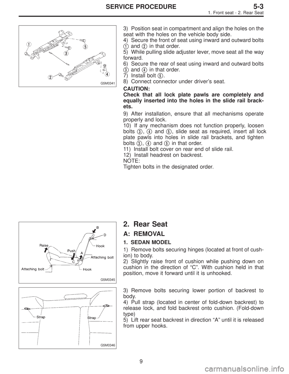
G5M0345
2. Rear Seat
A: REMOVAL
1. SEDAN MODEL
1) Remove bolts securing hinges (located at front of cush-
ion) to body.
2) Slightly raise front of cushion while pushing down on
cushion in the direction of“C”. With cushion held in that
position, move it forward until it is unhooked.
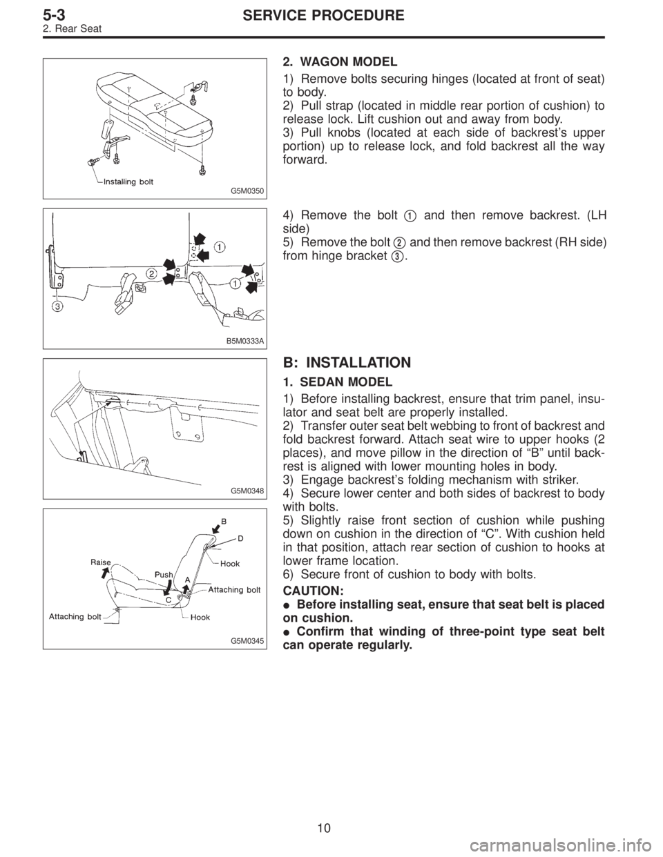
G5M0346
3) Remove bolts securing lower portion of backrest to
body.
4) Pull strap (located in center of fold-down backrest) to
release lock, and fold backrest onto cushion. (Fold-down
type)
5) Lift rear seat backrest in direction“A”until it is released
from upper hooks.
9
5-3SERVICE PROCEDURE
1. Front seat - 2. Rear Seat
Page 1553 of 2890

G5M0341
3) Position seat in compartment and align the holes on the
seat with the holes on the vehicle body side.
4) Secure the front of seat using inward and outward bolts
�
1and�2in that order.
5) While pulling slide adjuster lever, move seat all the way
forward.
6) Secure the rear of seat using inward and outward bolts
�
3and�4in that order.
7) Install bolt�
5.
8) Connect connector under driver’s seat.
CAUTION:
Check that all lock plate pawls are completely and
equally inserted into the holes in the slide rail brack-
ets.
9) After installation, ensure that all mechanisms operate
properly and lock.
10) If any mechanism does not function properly, loosen
bolts�
3,�4and�5, slide seat as required, insert all lock
plate pawls into holes in slide rail brackets, and tighten
bolts�
3,�4and�5in that order.
11) Install bolt cover on rear end of slide rail.
12) Install headrest on backrest.
NOTE:
Tighten bolts in the designated order.
G5M0345
2. Rear Seat
A: REMOVAL
1. SEDAN MODEL
1) Remove bolts securing hinges (located at front of cush-
ion) to body.
2) Slightly raise front of cushion while pushing down on
cushion in the direction of“C”. With cushion held in that
position, move it forward until it is unhooked.
G5M0346
3) Remove bolts securing lower portion of backrest to
body.
4) Pull strap (located in center of fold-down backrest) to
release lock, and fold backrest onto cushion. (Fold-down
type)
5) Lift rear seat backrest in direction“A”until it is released
from upper hooks.
9
5-3SERVICE PROCEDURE
1. Front seat - 2. Rear Seat
Page 1554 of 2890

G5M0350
2. WAGON MODEL
1) Remove bolts securing hinges (located at front of seat)
to body.
2) Pull strap (located in middle rear portion of cushion) to
release lock. Lift cushion out and away from body.
3) Pull knobs (located at each side of backrest’s upper
portion) up to release lock, and fold backrest all the way
forward.
B5M0333A
4) Remove the bolt�1and then remove backrest. (LH
side)
5) Remove the bolt�
2and then remove backrest (RH side)
from hinge bracket�
3.
G5M0348
G5M0345
B: INSTALLATION
1. SEDAN MODEL
1) Before installing backrest, ensure that trim panel, insu-
lator and seat belt are properly installed.
2) Transfer outer seat belt webbing to front of backrest and
fold backrest forward. Attach seat wire to upper hooks (2
places), and move pillow in the direction of“B”until back-
rest is aligned with lower mounting holes in body.
3) Engage backrest’s folding mechanism with striker.
4) Secure lower center and both sides of backrest to body
with bolts.
5) Slightly raise front section of cushion while pushing
down on cushion in the direction of“C”. With cushion held
in that position, attach rear section of cushion to hooks at
lower frame location.
6) Secure front of cushion to body with bolts.
CAUTION:
�Before installing seat, ensure that seat belt is placed
on cushion.
�Confirm that winding of three-point type seat belt
can operate regularly.
10
5-3SERVICE PROCEDURE
2. Rear Seat
Page 1560 of 2890
![SUBARU LEGACY 1996 Service Repair Manual B5M0048A
3. CENTER PILLAR UPPER
<Ref. to 5-3 [C500].>
1) Remove front pillar upper trim.
2) Remove upper anchor of front seat belt.
3) Remove center pillar upper trim panel.
4) Installation is in the SUBARU LEGACY 1996 Service Repair Manual B5M0048A
3. CENTER PILLAR UPPER
<Ref. to 5-3 [C500].>
1) Remove front pillar upper trim.
2) Remove upper anchor of front seat belt.
3) Remove center pillar upper trim panel.
4) Installation is in the](/manual-img/17/57433/w960_57433-1559.png)
B5M0048A
3. CENTER PILLAR UPPER
1) Remove front pillar upper trim.
2) Remove upper anchor of front seat belt.
3) Remove center pillar upper trim panel.
4) Installation is in the reverse order of removal.
CAUTION:
�The left and right ELR’s are not mutually inter-
changeable because different sensors are used.
�Be careful not to twist belts during installation.
G5M0363
4. FRONT PILLAR UPPER
Remove front pillar upper trim panel.
CAUTION:
Be sure to securely hook pawls of front pillar upper
trim panel on body flange.
B5M0043A
5. REAR PILLAR UPPER
1) Remove rear seat cushion and backrest.
2) Remove rear seat belt. (Lower anchor bolt)
3) Remove rear pillar upper trim panel.
[C500].>
4) Installation is in the reverse order of removal.
CAUTION:
Be sure to securely hook pawls of rear pillar upper trim
panel on body flange.
B5M0049
6. REAR PILLAR LOWER
1) Remove side sill rear upper cover trim.
2) Remove rear pillar lower trim.
B5M0044A
7. REAR QUARTER PILLAR UPPER
1) Remove rear seat belt. (Upper anchor bolt)
2) Remove cap strut.
3) Remove rear quarter upper front trim�
1.
4) Remove rear quarter upper rear trim�
2.
5) Installation is in the reverse order of removal.
CAUTION:
Be sure to securely hook pawls of rear quarter pillar
trim panel on body flange.
14
5-3SERVICE PROCEDURE
5. Inner Trim Panel
Page 1562 of 2890
1) Remove front seats.
2) Remove rear seat cushion.
3) Remove console box.
4) Remove front pillar lower trim panel.
5) Remove center pillar lower trim panel.
6) Remove side sill cover.
7) Remove fuel opener cover.
G5M0368
8) Remove clip under front seat.
9) Remove clip in toe board area.
NOTE:
When pulling out edge, do not pull mat alone; pull mat
together with edge.
Pry off two steel clips on side sill front cover and one on
side sill rear cover using screwdriver.
10) Remove mat hook.
11) Remove mat from toe board area.
12) Remove mat from heater module.
13) Roll mat, and take it out of opened rear door.
14) Installation is in the reverse order of removal.
NOTE:
�Secure mat firmly with hook and velcro tape.
�Insert mat edge firmly into the groove of side sill cover.
16
5-3SERVICE PROCEDURE
5. Inner Trim Panel
Page 1573 of 2890
G5M0295
4) Do not drop the airbag modulator parts, subject it to
high temperatures over 90°C (194°F), or apply oil, grease,
or water to it; otherwise, the internal parts may be damaged
and its reliability greatly lowered.
G5M0296
5) If any damage or open is found on the SRS airbag sys-
tem wire harness, do not attempt to repair using soldering,
etc. Be sure to replace the faulty harness with a new genu-
ine part.
G5M0297
6) Install the wire harness securely with the specified clips
so as to avoid interference or jamming with other parts.
7) Before connecting the airbag system to ground, make
sure that the grounding terminal is free from paint and
contamination.
5
5-5SERVICE PROCEDURE
1. Precaution
Page 1584 of 2890
G5M0312
3) Remove lower cover.
Disconnect airbag connector (AB3) and (AB8) below steer-
ing column.
CAUTION:
Do not reconnect airbag connector at steering column
until front sensors are securely re-installed.
G5M0313
4) Remove console box. Discon-
nect 2-pin blue connector (AB4) (right side front sensor)
and 2-pin orange connector (AB5) (left side front sensor)
from airbag control module.
G5M0314
5) Roll up floor mat and side sill cover.
[W5A10].> Remove front sensor harness from clip and pro-
tector.
6) Remove front wheels.
7) Remove front mud guard.
G5M0315
8) Remove wiring harness clips.
G5M0316
9) Remove grommet.
14
5-5SERVICE PROCEDURE
4. Front Sensor
Page 1585 of 2890
B5M0102
10) Remove front sensor.
B: INSTALLATION
Installation is in reverse order of removal procedures.
5. Main Harness
A: REMOVAL
1) Turn ignition switch off.
2) Disconnect ground cable from battery and wait for at
least 20 seconds before starting work.
G5M0312
3) Remove lower cover.
Disconnect airbag connector (AB3) and (AB8) below steer-
ing column.
CAUTION:
Do not reconnect airbag connector at steering column
until main harness are securely re-installed.
G5M0313
4) Remove console box. Discon-
nect 12-pin yellow connector (AB6) from airbag control
module.
15
5-5SERVICE PROCEDURE
4. Front Sensor - 5. Main Harness