Page 1316 of 2890
B4M0628
G: INSTALLATION
1) Install hydraulic unit and bracket.
Tightening torque:
32±7 N⋅m (3.3±0.7 kg-m, 23.9±5.1 ft-lb)
2) Connect brake pipes to their correct hydraulic unit con-
nections.
3) Connect connector to hydraulic unit.
4) Install canister.
5) Install air cleaner case.
6) Install air intake duct.
7) Connect ground cable to battery.
CAUTION:
Cover relay securely with rubber boot.
21. ABS/TCS Control Module
A: REMOVAL
1) Disconnect ground cable from battery.
2) Remove floor mat located under lower right side of front
seat.
B4M0643A
3) Remove screw which secure ABS/TCS control module
from the body.
4) Disconnect connector from ABS/TCS control module.
B: INSPECTION
Check that connector is connected correctly and that con-
nector terminal sliding resistance is correct.
107
4-4SERVICE PROCEDURE
20. Hydraulic Unit for ABS/TCS System - 21. ABS/TCS Control Module
Page 1317 of 2890
B4M0628
G: INSTALLATION
1) Install hydraulic unit and bracket.
Tightening torque:
32±7 N⋅m (3.3±0.7 kg-m, 23.9±5.1 ft-lb)
2) Connect brake pipes to their correct hydraulic unit con-
nections.
3) Connect connector to hydraulic unit.
4) Install canister.
5) Install air cleaner case.
6) Install air intake duct.
7) Connect ground cable to battery.
CAUTION:
Cover relay securely with rubber boot.
21. ABS/TCS Control Module
A: REMOVAL
1) Disconnect ground cable from battery.
2) Remove floor mat located under lower right side of front
seat.
B4M0643A
3) Remove screw which secure ABS/TCS control module
from the body.
4) Disconnect connector from ABS/TCS control module.
B: INSPECTION
Check that connector is connected correctly and that con-
nector terminal sliding resistance is correct.
107
4-4SERVICE PROCEDURE
20. Hydraulic Unit for ABS/TCS System - 21. ABS/TCS Control Module
Page 1320 of 2890

B4M0996
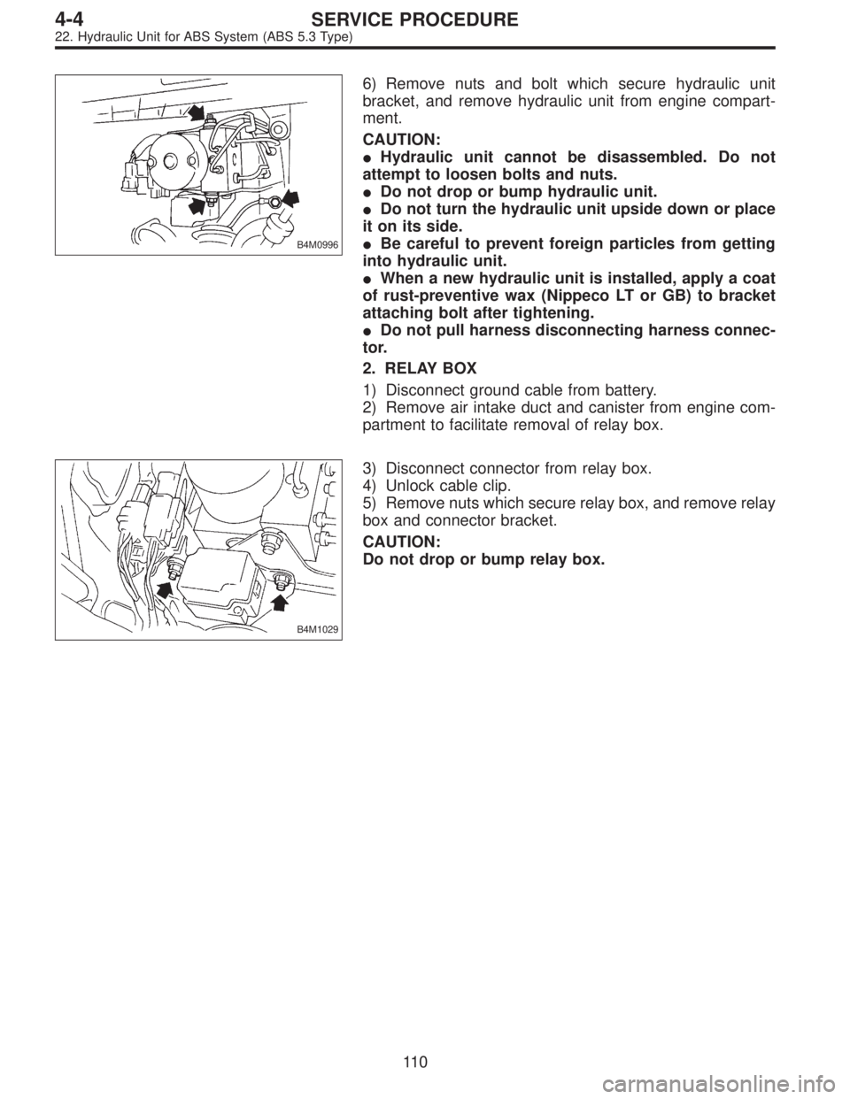
6) Remove nuts and bolt which secure hydraulic unit
bracket, and remove hydraulic unit from engine compart-
ment.
CAUTION:
�Hydraulic unit cannot be disassembled. Do not
attempt to loosen bolts and nuts.
�Do not drop or bump hydraulic unit.
�Do not turn the hydraulic unit upside down or place
it on its side.
�Be careful to prevent foreign particles from getting
into hydraulic unit.
�When a new hydraulic unit is installed, apply a coat
of rust-preventive wax (Nippeco LT or GB) to bracket
attaching bolt after tightening.
�Do not pull harness disconnecting harness connec-
tor.
2. RELAY BOX
1) Disconnect ground cable from battery.
2) Remove air intake duct and canister from engine com-
partment to facilitate removal of relay box.
B4M1029
3) Disconnect connector from relay box.
4) Unlock cable clip.
5) Remove nuts which secure relay box, and remove relay
box and connector bracket.
CAUTION:
Do not drop or bump relay box.
11 0
4-4SERVICE PROCEDURE
22. Hydraulic Unit for ABS System (ABS 5.3 Type)
Page 1328 of 2890
B4M0996
E: INSTALLATION
1. HYDRAULIC UNIT
1) Install hydraulic unit.
Tightening torque:
18±5 N⋅m (1.8±0.5 kg-m, 13.0±3.6 ft-lb)
2) Connect hydraulic unit ground cable to body.
Tightening torque:
32±10 N⋅m (3.3±1.0 kg-m, 24±7 ft-lb)
3) Connect brake pipes to their correct hydraulic unit con-
nections.
B4M1031A
4) Secure hydraulic unit connector to connector bracket.
CAUTION:
Align connector with mating receptacle.
5) Using cable clip, secure hydraulic unit harness to relay
box harness.
CAUTION:
Make sure hydraulic unit harness band is secured
beneath cable clip.
6) Connect connector to hydraulic unit.
7) Install canister.
8) Install air intake duct.
9) Connect ground cable to battery.
10) Bleed air from the brake system.
B4M1029
2. RELAY BOX
1) Install relay box and connector bracket.
Tightening torque:
18±5 N⋅m (1.8±0.5 kg-m, 13.0±3.6 ft-lb)
11 8
4-4SERVICE PROCEDURE
22. Hydraulic Unit for ABS System (ABS 5.3 Type)
Page 1329 of 2890
B4M1031A
2) Secure relay box connector to connector bracket.
CAUTION:
Align connector with mating receptacle.
3) Using cable clip, secure hydraulic unit harness to relay
box harness.
CAUTION:
Make sure hydraulic unit harness band is secured
beneath cable clip.
4) Connect connector to relay box.
5) Install canister.
6) Install air intake duct.
7) Connect ground cable to battery.
B4M1002
23. ABS Control Module (ABS 5.3 Type)
A: REMOVAL
1. LHD MODEL
1) Turn ignition switch to OFF.
2) Remove front pillar lower trim.
3) Remove glove box.
4) Remove glove box bracket.
B4M1003
5) Remove pocket back panel.
B4M1004
6) Remove bolt from bracket.
11 9
4-4SERVICE PROCEDURE
22. Hydraulic Unit for ABS System (ABS 5.3 Type) - 23. ABS Control Module (ABS 5.3 Type)
Page 1330 of 2890
B4M1031A
2) Secure relay box connector to connector bracket.
CAUTION:
Align connector with mating receptacle.
3) Using cable clip, secure hydraulic unit harness to relay
box harness.
CAUTION:
Make sure hydraulic unit harness band is secured
beneath cable clip.
4) Connect connector to relay box.
5) Install canister.
6) Install air intake duct.
7) Connect ground cable to battery.
B4M1002
23. ABS Control Module (ABS 5.3 Type)
A: REMOVAL
1. LHD MODEL
1) Turn ignition switch to OFF.
2) Remove front pillar lower trim.
3) Remove glove box.
4) Remove glove box bracket.
B4M1003
5) Remove pocket back panel.
B4M1004
6) Remove bolt from bracket.
11 9
4-4SERVICE PROCEDURE
22. Hydraulic Unit for ABS System (ABS 5.3 Type) - 23. ABS Control Module (ABS 5.3 Type)
Page 1331 of 2890
B4M1005
7) Remove bolt cover and bolt.
B4M1006
8) Remove ABSCM upper mounting bolt.
B4M1045A
9) Pull the lower part of the instrument panel rearward 5
cm (1.97 in).
CAUTION:
When pulled more than 6 cm (2.4 in), the instrument
panel may be deformed.
NOTE:
At this time, instrument panel securing clips can be
removed.
B4M1008
10) Remove two ABSCM lower mounting bolts from the
lower part of the instrument panel.
B4M1009A
11) While holding the lower part of instrument panel rear-
ward 5 cm (1.97 in) remove the ABSCM.
CAUTION:
When pulled more than 6 cm (2.4 in), the instrument
panel may be deformed.
12) Disconnect connector from ABSCM.
CAUTION:
Do not drop or bump ABSCM.
120
4-4SERVICE PROCEDURE
23. ABS Control Module (ABS 5.3 Type)
Page 1345 of 2890

2. BRAKE AND CLUTCH PEDAL (LHD MODEL)
1) Disconnect ground cable from battery.
2) Disconnect clutch cable from release lever.
3) Remove instrument panel lower cover from instrument
panel.
4) Disconnect the following parts from pedal bracket.
(1) Operating rod of brake booster
(2) Electrical connectors (for stop light switch, etc.)
5) Remove clevis pin which secures pedal to push rod.
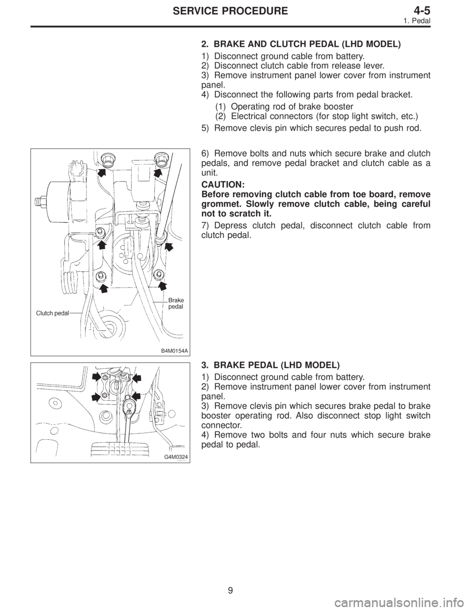
B4M0154A
6) Remove bolts and nuts which secure brake and clutch
pedals, and remove pedal bracket and clutch cable as a
unit.
CAUTION:
Before removing clutch cable from toe board, remove
grommet. Slowly remove clutch cable, being careful
not to scratch it.
7) Depress clutch pedal, disconnect clutch cable from
clutch pedal.
G4M0324
3. BRAKE PEDAL (LHD MODEL)
1) Disconnect ground cable from battery.
2) Remove instrument panel lower cover from instrument
panel.
3) Remove clevis pin which secures brake pedal to brake
booster operating rod. Also disconnect stop light switch
connector.
4) Remove two bolts and four nuts which secure brake
pedal to pedal.
9
4-5SERVICE PROCEDURE
1. Pedal