Page 1185 of 2890
G4M0186
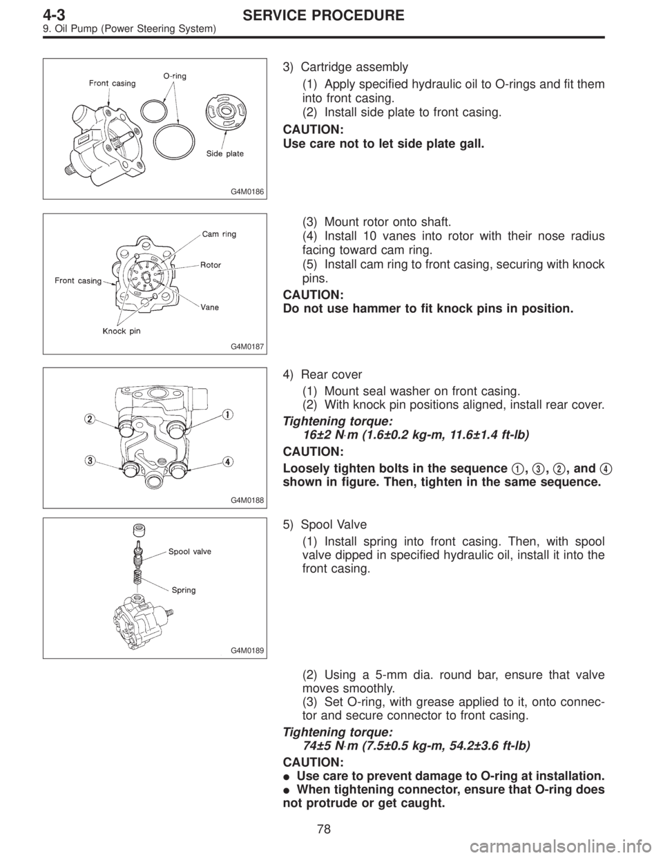
3) Cartridge assembly
(1) Apply specified hydraulic oil to O-rings and fit them
into front casing.
(2) Install side plate to front casing.
CAUTION:
Use care not to let side plate gall.
G4M0187
(3) Mount rotor onto shaft.
(4) Install 10 vanes into rotor with their nose radius
facing toward cam ring.
(5) Install cam ring to front casing, securing with knock
pins.
CAUTION:
Do not use hammer to fit knock pins in position.
G4M0188
4) Rear cover
(1) Mount seal washer on front casing.
(2) With knock pin positions aligned, install rear cover.
Tightening torque:
16±2 N⋅m (1.6±0.2 kg-m, 11.6±1.4 ft-lb)
CAUTION:
Loosely tighten bolts in the sequence�
1,�3,�2, and�4
shown in figure. Then, tighten in the same sequence.
G4M0189
5) Spool Valve
(1) Install spring into front casing. Then, with spool
valve dipped in specified hydraulic oil, install it into the
front casing.
(2) Using a 5-mm dia. round bar, ensure that valve
moves smoothly.
(3) Set O-ring, with grease applied to it, onto connec-
tor and secure connector to front casing.
Tightening torque:
74±5 N⋅m (7.5±0.5 kg-m, 54.2±3.6 ft-lb)
CAUTION:
�Use care to prevent damage to O-ring at installation.
�When tightening connector, ensure that O-ring does
not protrude or get caught.
78
4-3SERVICE PROCEDURE
9. Oil Pump (Power Steering System)
Page 1244 of 2890
G4M0393
A: REMOVAL
1. BRAKE DRUM AND SHOE
1) Loosen wheel nuts, jack-up vehicle, support it with rigid
racks, and remove wheel.
2) Release parking brake.
3) Remove brake drum from brake assembly.
G4M0242
NOTE:
If it is difficult to remove brake drum, remove adjusting hole
cover from back plate, and then, turn adjuster assembly
pawls using a slot-type screwdriver until brake shoe sepa-
rates from the drum.
G4M0395
4) Hold hold-down pin by securing rear of back plate with
your hand.
5) Disconnect hold-down cup from hold-down pin by rotat-
ing hold-down cup.
G4M0396
6) Disconnect lower shoe return spring from shoes.
G4M0397
7) Remove shoes one by one from back plate with
adjuster.
CAUTION:
Be careful not to bend parking brake cable excessively
when removing brake shoes.
8) Disconnect parking brake cable from parking lever.
39
4-4SERVICE PROCEDURE
3. Rear Drum Brake
Page 1248 of 2890
G4M0407
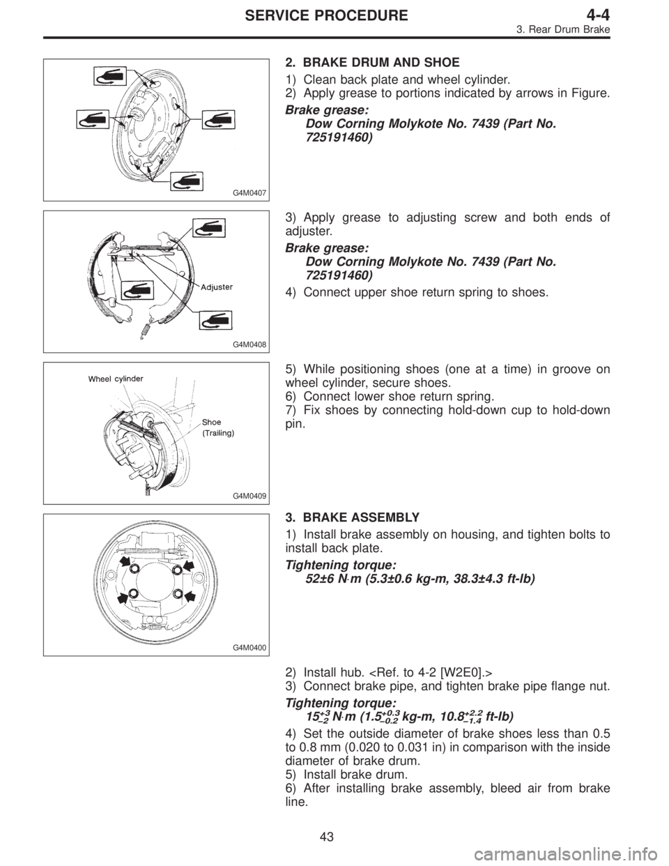
2. BRAKE DRUM AND SHOE
1) Clean back plate and wheel cylinder.
2) Apply grease to portions indicated by arrows in Figure.
Brake grease:
Dow Corning Molykote No. 7439 (Part No.
725191460)
G4M0408
3) Apply grease to adjusting screw and both ends of
adjuster.
Brake grease:
Dow Corning Molykote No. 7439 (Part No.
725191460)
4) Connect upper shoe return spring to shoes.
G4M0409
5) While positioning shoes (one at a time) in groove on
wheel cylinder, secure shoes.
6) Connect lower shoe return spring.
7) Fix shoes by connecting hold-down cup to hold-down
pin.
G4M0400
3. BRAKE ASSEMBLY
1) Install brake assembly on housing, and tighten bolts to
install back plate.
Tightening torque:
52±6 N⋅m (5.3±0.6 kg-m, 38.3±4.3 ft-lb)
2) Install hub.
3) Connect brake pipe, and tighten brake pipe flange nut.
Tightening torque:
15
+3
�2N⋅m (1.5+0.3
�0.2kg-m, 10.8+2.2
�1.4ft-lb)
4) Set the outside diameter of brake shoes less than 0.5
to 0.8 mm (0.020 to 0.031 in) in comparison with the inside
diameter of brake drum.
5) Install brake drum.
6) After installing brake assembly, bleed air from brake
line.
43
4-4SERVICE PROCEDURE
3. Rear Drum Brake
Page 1251 of 2890
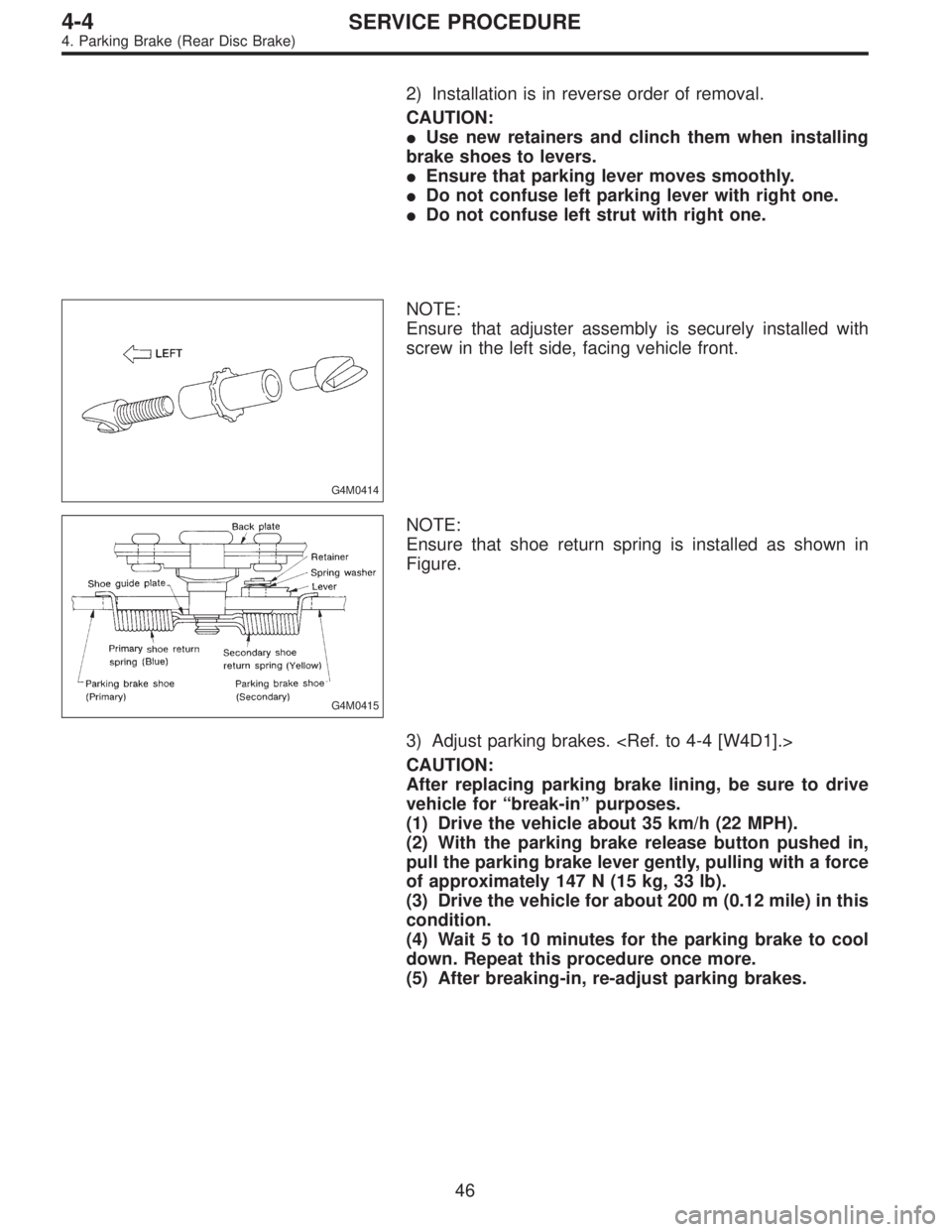
2) Installation is in reverse order of removal.
CAUTION:
�Use new retainers and clinch them when installing
brake shoes to levers.
�Ensure that parking lever moves smoothly.
�Do not confuse left parking lever with right one.
�Do not confuse left strut with right one.
G4M0414
NOTE:
Ensure that adjuster assembly is securely installed with
screw in the left side, facing vehicle front.
G4M0415
NOTE:
Ensure that shoe return spring is installed as shown in
Figure.
3) Adjust parking brakes.
CAUTION:
After replacing parking brake lining, be sure to drive
vehicle for“break-in”purposes.
(1) Drive the vehicle about 35 km/h (22 MPH).
(2) With the parking brake release button pushed in,
pull the parking brake lever gently, pulling with a force
of approximately 147 N (15 kg, 33 lb).
(3) Drive the vehicle for about 200 m (0.12 mile) in this
condition.
(4) Wait 5 to 10 minutes for the parking brake to cool
down. Repeat this procedure once more.
(5) After breaking-in, re-adjust parking brakes.
46
4-4SERVICE PROCEDURE
4. Parking Brake (Rear Disc Brake)
Page 1255 of 2890
D: ASSEMBLY
1. PRECAUTIONS FOR ASSEMBLING
1) When assembling, be sure to use recommended brake
fluid.
2) Ensure that the inside wall of cylinder, pistons, and pis-
ton cups are free from dirt when assembling.
3) Be extremely careful not to damage, scratch, or dent
cylinder inside wall, pistons, and piston cups.
4) Do not drop parts. Never attempt to use any part that
has been dropped accidentally.
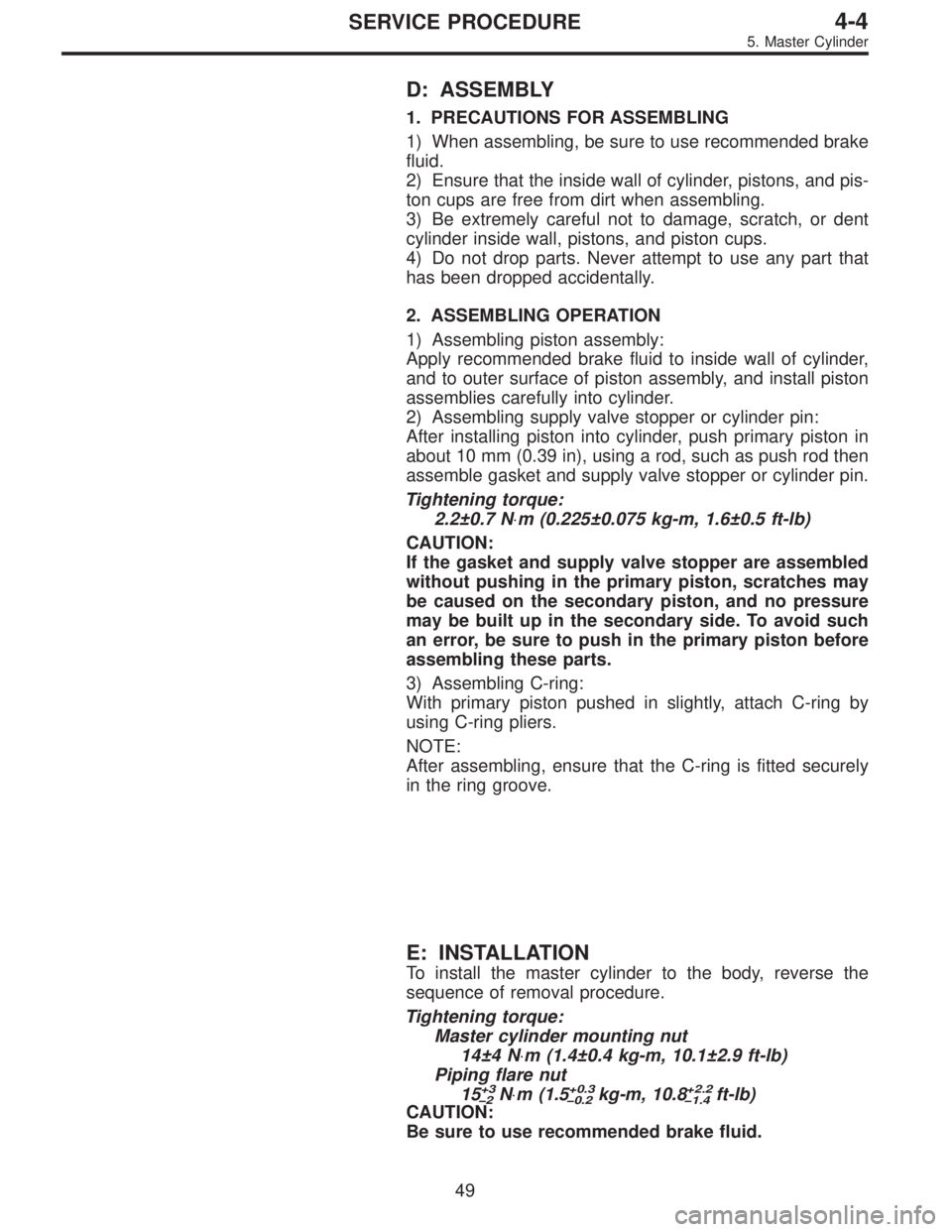
2. ASSEMBLING OPERATION
1) Assembling piston assembly:
Apply recommended brake fluid to inside wall of cylinder,
and to outer surface of piston assembly, and install piston
assemblies carefully into cylinder.
2) Assembling supply valve stopper or cylinder pin:
After installing piston into cylinder, push primary piston in
about 10 mm (0.39 in), using a rod, such as push rod then
assemble gasket and supply valve stopper or cylinder pin.
Tightening torque:
2.2±0.7 N⋅m (0.225±0.075 kg-m, 1.6±0.5 ft-lb)
CAUTION:
If the gasket and supply valve stopper are assembled
without pushing in the primary piston, scratches may
be caused on the secondary piston, and no pressure
may be built up in the secondary side. To avoid such
an error, be sure to push in the primary piston before
assembling these parts.
3) Assembling C-ring:
With primary piston pushed in slightly, attach C-ring by
using C-ring pliers.
NOTE:
After assembling, ensure that the C-ring is fitted securely
in the ring groove.
E: INSTALLATION
To install the master cylinder to the body, reverse the
sequence of removal procedure.
Tightening torque:
Master cylinder mounting nut
14±4 N⋅m (1.4±0.4 kg-m, 10.1±2.9 ft-lb)
Piping flare nut
15
+3
�2N⋅m (1.5+0.3
�0.2kg-m, 10.8+2.2
�1.4ft-lb)
CAUTION:
Be sure to use recommended brake fluid.
49
4-4SERVICE PROCEDURE
5. Master Cylinder
Page 1257 of 2890
B4M0616A
B4M0617A
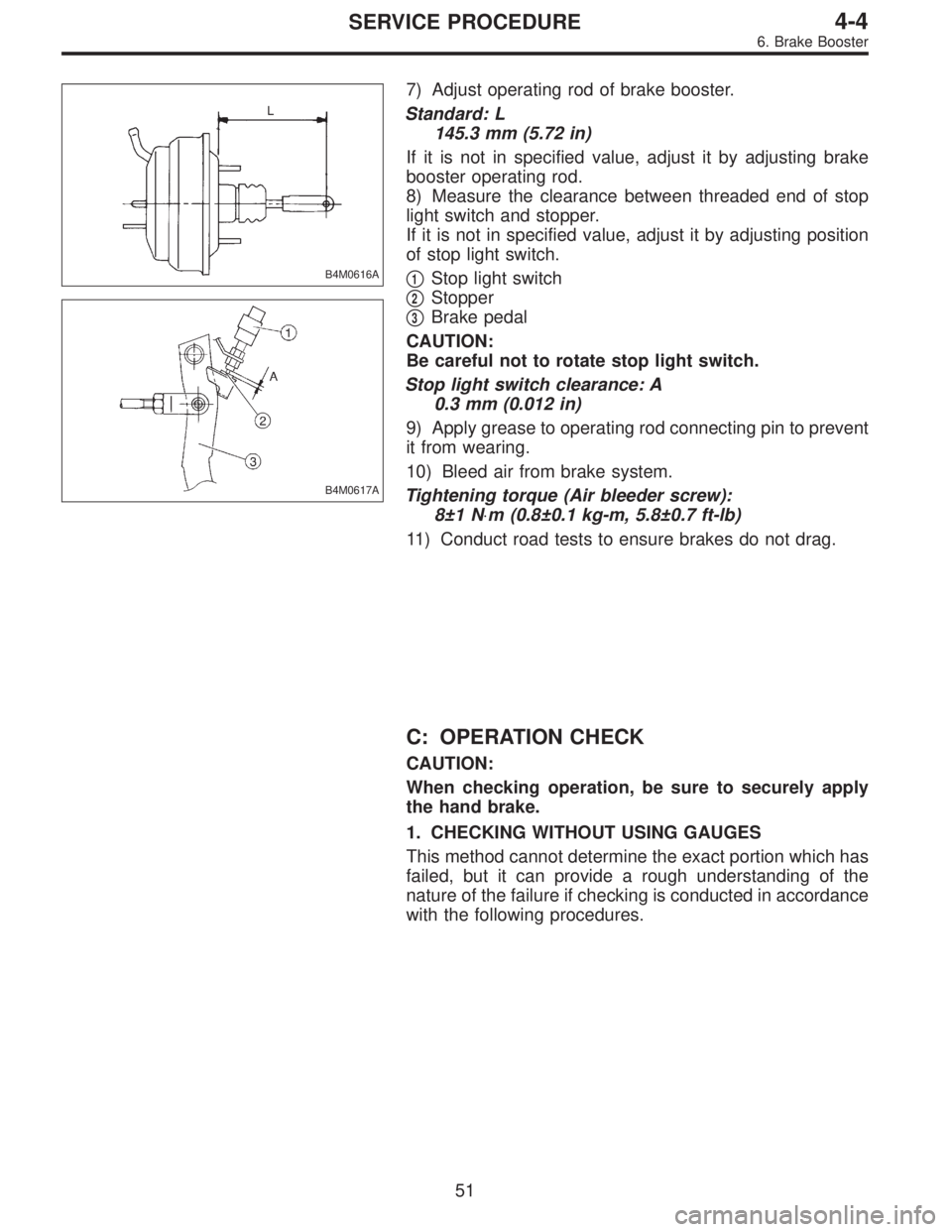
7) Adjust operating rod of brake booster.
Standard: L
145.3 mm (5.72 in)
If it is not in specified value, adjust it by adjusting brake
booster operating rod.
8) Measure the clearance between threaded end of stop
light switch and stopper.
If it is not in specified value, adjust it by adjusting position
of stop light switch.
�
1Stop light switch
�
2Stopper
�
3Brake pedal
CAUTION:
Be careful not to rotate stop light switch.
Stop light switch clearance: A
0.3 mm (0.012 in)
9) Apply grease to operating rod connecting pin to prevent
it from wearing.
10) Bleed air from brake system.
Tightening torque (Air bleeder screw):
8±1 N⋅m (0.8±0.1 kg-m, 5.8±0.7 ft-lb)
11) Conduct road tests to ensure brakes do not drag.
C: OPERATION CHECK
CAUTION:
When checking operation, be sure to securely apply
the hand brake.
1. CHECKING WITHOUT USING GAUGES
This method cannot determine the exact portion which has
failed, but it can provide a rough understanding of the
nature of the failure if checking is conducted in accordance
with the following procedures.
51
4-4SERVICE PROCEDURE
6. Brake Booster
Page 1262 of 2890
G4M0426
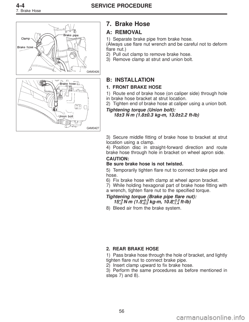
7. Brake Hose
A: REMOVAL
1) Separate brake pipe from brake hose.
(Always use flare nut wrench and be careful not to deform
flare nut.)
2) Pull out clamp to remove brake hose.
3) Remove clamp at strut and union bolt.
G4M0427
B: INSTALLATION
1. FRONT BRAKE HOSE
1) Route end of brake hose (on caliper side) through hole
in brake hose bracket at strut location.
2) Tighten end of brake hose at caliper using a union bolt.
Tightening torque (Union bolt):
18±3 N⋅m (1.8±0.3 kg-m, 13.0±2.2 ft-lb)
3) Secure middle fitting of brake hose to bracket at strut
location using a clamp.
4) Position disc in straight-forward direction and route
brake hose through hole in bracket on wheel apron side.
CAUTION:
Be sure brake hose is not twisted.
5) Temporarily tighten flare nut to connect brake pipe and
hose.
6) Fix brake hose with clamp at wheel apron bracket.
7) While holding hexagonal part of brake hose fitting with
a wrench, tighten flare nut to the specified torque.
Tightening torque (Brake pipe flare nut):
15
+3
�2N⋅m (1.5+0.3
�0.2kg-m, 10.8+2.2
�1.4ft-lb)
8) Bleed air from the brake system.
2. REAR BRAKE HOSE
1) Pass brake hose through the hole of bracket, and lightly
tighten flare nut to connect brake pipe.
2) Insert clamp upward to fix brake hose.
3) Perform the same procedures as before mentioned in
steps 7) and 8).
56
4-4SERVICE PROCEDURE
7. Brake Hose
Page 1269 of 2890
11. Air Bleeding (Without TCS model)
A: GENERAL RULES FOR EFFECTIVE
BLEEDING
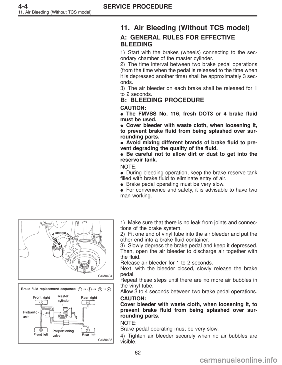
1) Start with the brakes (wheels) connecting to the sec-
ondary chamber of the master cylinder.
2) The time interval between two brake pedal operations
(from the time when the pedal is released to the time when
it is depressed another time) shall be approximately 3 sec-
onds.
3) The air bleeder on each brake shall be released for 1
to 2 seconds.
B: BLEEDING PROCEDURE
CAUTION:
�The FMVSS No. 116, fresh DOT3 or 4 brake fluid
must be used.
�Cover bleeder with waste cloth, when loosening it,
to prevent brake fluid from being splashed over sur-
rounding parts.
�Avoid mixing different brands of brake fluid to pre-
vent degrading the quality of the fluid.
�Be careful not to allow dirt or dust to get into the
reservoir tank.
NOTE:
�During bleeding operation, keep the brake reserve tank
filled with brake fluid to eliminate entry of air.
�Brake pedal operating must be very slow.
�For convenience and safety, it is advisable to have two
man working.
G4M0434
G4M0435
1) Make sure that there is no leak from joints and connec-
tions of the brake system.
2) Fit one end of vinyl tube into the air bleeder and put the
other end into a brake fluid container.
3) Slowly depress the brake pedal and keep it depressed.
Then, open the air bleeder to discharge air together with
the fluid.
Release air bleeder for 1 to 2 seconds.
Next, with the bleeder closed, slowly release the brake
pedal.
Repeat these steps until there are no more air bubbles in
the vinyl tube.
Allow 3 to 4 seconds between two brake pedal operations.
CAUTION:
Cover bleeder with waste cloth, when loosening it, to
prevent brake fluid from being splashed over sur-
rounding parts.
NOTE:
Brake pedal operating must be very slow.
4) Tighten air bleeder securely when no air bubbles are
visible.
62
4-4SERVICE PROCEDURE
11. Air Bleeding (Without TCS model)